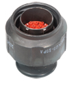
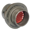
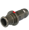
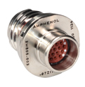
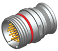
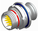
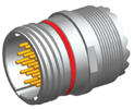
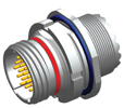
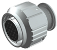
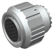
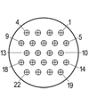
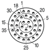
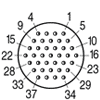
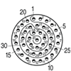
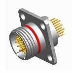
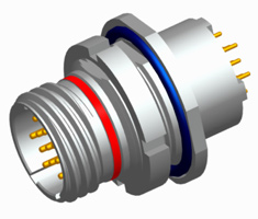
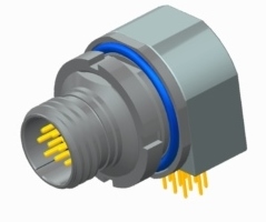
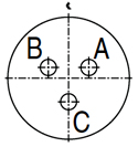
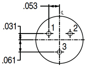
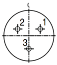
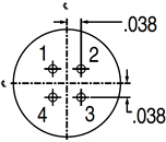
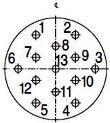
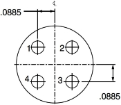
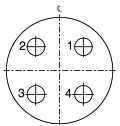
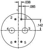
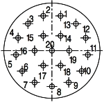
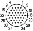
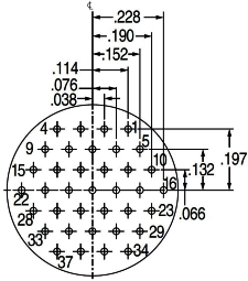
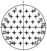
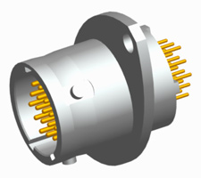
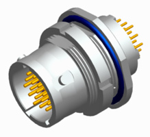
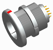
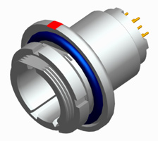
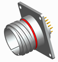
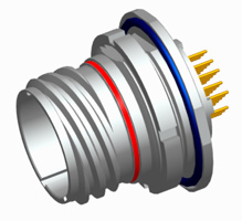
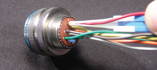
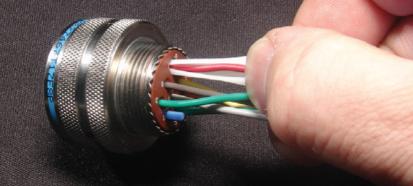
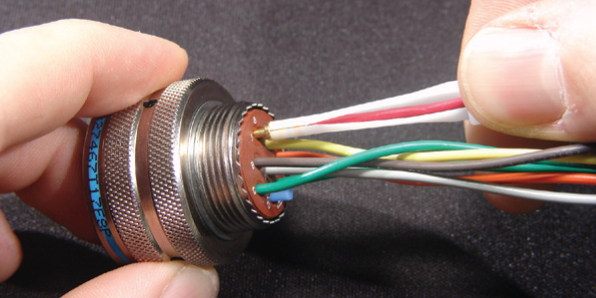
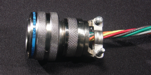
Amphenol 2M Series Micro-Miniature Connectors
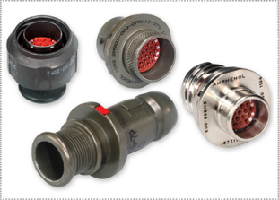
INTERMATEABLE WITH GLENAIR MIGHTY MOUSE CONNECTORS
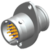
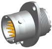
Amphenol 2M series micro-miniature connectors are fully-guaranteed to be intermateable with Glenair Mighty Mouse connectors. The 2M Series is a superior and versatile connector designed and tested to mil-spec standards, comparable to MIL-DTL-38999.
The Amphenol 2M series is a light-weight, micro-miniature circular connector option for mil-spec performance that can withstand harsh environments that require smaller, faster and stronger connectors such as armored vehicles, data acquisition equipment, aero planes, helicopters, avionic calculators, missiles and drones.
Amphenol’s micro-miniature 2M series meets D38999 specifications for vibration and shielding, offering better performance than Glenair Mighty Mouse connectors. These Amphenol 2M series connectors are perfect for aviation, military communications, and UAV applications. They are quick-mating and a variety of styles are available. For full product details on Amphenol 2M series connectors, please see our specifications below.
For full product details on Amphenol 2M series connectors, please see our specifications below.
See how Amphenol 2M Series connectors provided a rugged, high-performance solution for tactical robots in demanding environments, explore our case study here.
|
FEATURESAMPHENOL 2M SERIES FEATURES
2M801 2M803 2M804 2M805 Type Dual-Start ACME Thread Bayonet Push-Pull Tri-Start ACME Thread # of Contacts 1 to 130 1 to 55 1 to 55 1 to 130 Coupling Type Threaded Coupling 1-1/2 turns to fully mate 1/4 Turn Lock Bayonet Push-Pull Quick-Disconnect Tri-Start Thread Ratched Sealing MIL-STD-810 Method 512 1 Meter for 1-Hour Splashproof MIL-STD-810 Method 512 1 Meter for 1-Hour MIL-STD-810 Method 512 1 Meter for 1-Hour EMI-Shielding Very Good Fair Excellent Excellent Mating Cycles 2000 Cycles 250 Cycles Aluminum; 500 Cycles Stainless Steel 2000 Cycles 500 Cycles Electrical Performance Size 12: 23A, 1800 VAC Size 12: 23A, 1800 VAC Size 12: 23A, 1800 VAC Size 12: 23A, 1800 VAC Shock & Vibration 43.9 g's Random Vibration; 37 g’s Random Vibration; 300 g’s Shock 37 g’s Random Vibration; 300 g’s Shock 43.9 g's Random Vibration; MATERIALS & FINISHESAMPHENOL 2M SERIES MATERIALS & FINISHES
Shell Aluminum alloy 6061 T6, stainless steel passivated
Insert Polyphenylene sulfide (PPS)
Contact Retention Clip Beryllium copper, heat-treated, unplated
Contacts 50u” gold-plated copper alloy
Socket Contact Hood Passivated stainless steel
Grommet & Seals Fluorosilicone rubber
Adhesives Epoxy film & RTV'S
Potting Compound for PCB & Solder Versions High-strength epoxy
ELECTRICAL DATAAMPHENOL 2M SERIES ELECTRICAL DATA
Contact Sizes 23, 20, 20HD, 16, & 12 AWG
Operating Voltage & Test Voltage (Mated Condition) Contact Size 23 20 20HD 16 12 Sea Level VAC 500 1800 750 1800 1800 40,000 Feet VAC 100 325 150 1000 1000 Current Rating (Max) Contact Size Amperes 23 5 20 7.5 16 13 12 23 Contact Resistance Wire Size Test Current Max Voltage Drop 12 23 42 14 17 40 16 13 49 20 7.5 55 22 5 73 24 3 45 26 2 52 28 1.5 54 Insulation Resistance 5,000 megaohms minimum
MECHANICALAMPHENOL 2M SERIES MECHANICAL
Operating Temperature -85° F to +302° F (-65°C to +150° C) aluminium
-85° F to +392° F (-65°C to +200° C) stainless steel Sealing 1 meter for 1-hour (2M803 splashproof)
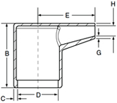
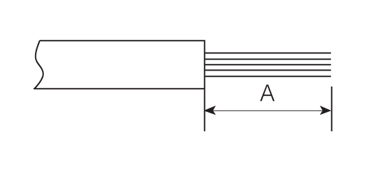
Insulation Strip Length Contact Size Strip Length 23 0.150 (3.81) 20 0.188 (2.54) 20HD 0.150 (3.81) 16 0.188 (2.54) 12 0.188 (2.54) All dimensions in inches (millimeters in parentheses) Mating Life 2000 cycles; 2M803 aluminum 250 cycles
Salt Spray Plating C & M: 48-hours
Plating MT, NF, ZM, ZN, ZNU, UCR: 500-hours Fungus Fungus inert
Random Vibration 2M801 & 2M805: 43.9g ; 2M803 & 2M804: 37g
Gunfire Vibration No discontinuity greater than 1-microsecond; no cracking, breaking or loosening of parts, plug shall not disengage from receptacle. Connectors meet electrical requirements after vibration test.
Shock 300 G, half-sine, 3ms, 3 axes
EMI-Shielding Effectiveness 55 dB min from 100 MHz to 1000 MHz
Contact Type Crimp, solder or printed circuit
Number of Contacts 1 to 130
Contact Retention Contact Size Min. Pounds Min. Newtons 23 10 45 20 15 67 20HD 10 45 16 25 111 12 25 111 Contact Separation Force Contact Size Min. Ounces Min. Newtons 23 0.5 0.14 20 0.7 0.19 20HD 0.7 0.19 16 2.0 0.56 12 3.0 0.83 Coupling Torque Shell Size Inch / Pounds Series 2M801 Series 2M805 5, 6, 7 8,9 8 8, 9 10, 11 9 10 12 12 12, 13 15 16 14, 15 18 28 16, 17 19 24 21 - 32 - 23 36 Polarization Dual-Start ACME Thread coupling, 3 keyways with optional keyway rotations, note insert remained fixed.
|
|
AMPHENOL 2M SERIES APPLICATIONS
|
2M 801 - CRIMPAMPHENOL 2M SERIES 2M 801 DUAL-START ACME THREADS
EXAMPLE 1 2 3 4 5 6 2M801-009-07 NF 24-61 P A -501 SHELL STYLE SERVICE CLASS SHELL STYLE CONTACT TYPE KEYING MODIFIER STEP 1: SELECT SHELL STYLE, PLUG OR RECEPTACLE
* Add “-501” to the suffix of Jam Nut version to include a Hex Nut instead of a Spanner Nut. See Step 6. Read Less STEP 2: SELECT CLASS
 C = Aluminum/ Black Anodize (Non-Conductive) (RoHS) M = Aluminum/ Electroless Nickel (RoHS) NF = Aluminum/ Cadmium with Olive Drab Chromate MT = Aluminum/ Nickel-PTFE (Durmalon) (RoHS) Z1 = Stainless Steel/ Passivated ZM = Stainless Steel/ Electroless Nickel (RoHS) ZN = Aluminum/ Zinc-Nickel with Olive Drab Chromate ZNU = Aluminum/ Zinc-Nickel with Black Chromate (RoHS) Read Less STEP 3: SELECT LAYOUT

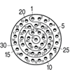
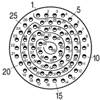
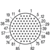
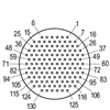
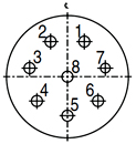
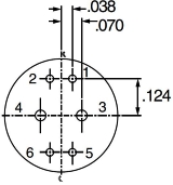
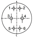
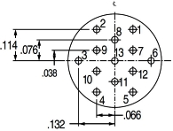
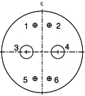
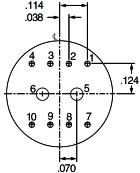
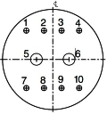
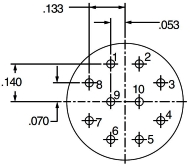
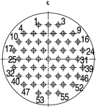
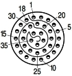
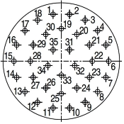
Contact Size Layout # of Contacts 23 20 20HD 16 12 5-3 3 3 6-1 1 1 6-4 4 4 6-6 6 6 6-7 7 7 6-23 3 3 7-1 1 1 7-10 10 10 7-25 5 5 8-2 2 2 8-13 13 13 8-28 8 8 8-200 6 4 2 9-4 4 4 9-19 19 19 9-200 6 4 2 9-201 10 8 2 9-210 10 10 10-2 2 2 10-5 5 5 10-26 26 26 10-200 13 12 1 10-201 6 4 2 10-202 10 8 2 13-2 2 2 13-3 3 3 13-7 7 7 13-37 37 37 13-200 8 6 2 13-201 12 10 2 13-220 20 20 16-5 5 5 16-12 12 12 16-55 55 55 16-235 35 35 17-7 7 7 17-14 14 14 17-85 85 85 17-241 41 41 21-12 12 12 21-22 22 22 21-130 130 130 21-269 69 69 LAYOUT BY NUMBER OF CONTACTS
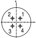
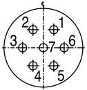
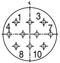
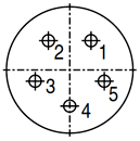
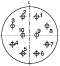
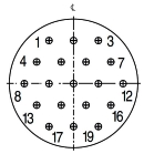
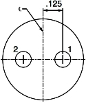
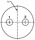
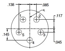
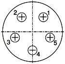
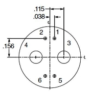
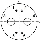
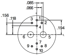
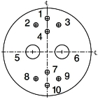
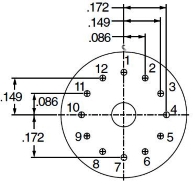
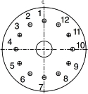
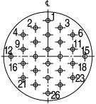
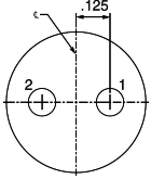
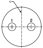
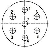
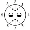
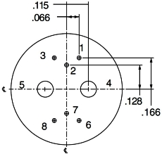
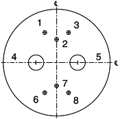
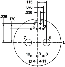
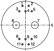
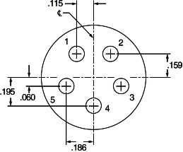
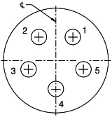
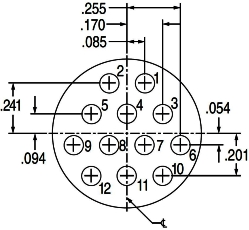
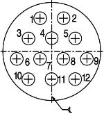
Front face of pin inserts shown. (Sockets mirror image) Contacts 1 2
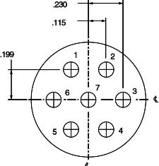
2M801 6-1 7-1 8-2 10-2 13-2 2M803 6-1 7-1 8-2 10-2 12-2 2M804 6-1 7-1 8-2 10-2 12-2 2M805 8-1 9-1 10-2 12-2 15-2 # of Contacts & Size 1#26 1#12 2#16 2#12 2#12 DWV Voltage (VAC) 1800 1800 1800 1800 1800 Contacts 3 4
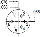
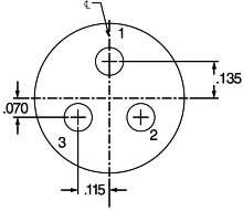
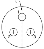
2M801 5-3 6-23 13-3 6-4 9-4 2M803 5-3 6-23 12-3 6-4 9-4 2M804 5-3 6-23 12-3 6-4 9-4 2M805 N/A 8-23 15-3 8-4 11-4 # of Contacts & Size 3#23 3#20HD 3#12 4#23 4#16 DWV Voltage (VAC) 500 750 1800 500 1800 Contacts 5 6
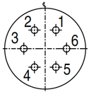
2M801 7-25 10-5 16-5 6-6 8-200 2M803 7-25 10-5 14-5 6-6 8-200 2M804 7-25 10-5 14-5 6-6 8-200 2M805 9-25 12-5 18-5 8-6 10-200 # of Contacts & Size 5#20HD 5#16 5#12 6#23 4#23, 2#20 DWV Voltage (VAC) 750 1800 1800 500 1000 (#20), 500 (#23) Contacts 6 (Cont.) 7
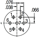
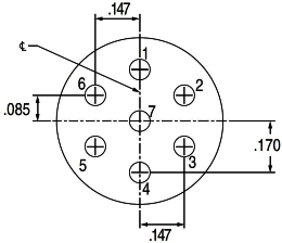
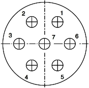
2M801 9-200 10-201 6-7 13-7 17-7 2M803 9-200 10-201 6-7 12-7 NA 2M804 9-200 10-201 6-7 12-7 NA 2M805 11-200 12-201 8-7 15-7 19-7 # of Contacts & Size 4#23, 2#16 4#23, 2#12 7#23 7#16 7#12 DWV Voltage (VAC) 1800 (#16), 500 (#23) 1800 (#12), 500 (#23) 500 1800 1800 Contacts 8 10
2M801 8-28 13-200 7-10 9-201 9-210 10-202 2M803 8-28 13-200 7-10 9-201 9-210 10-202 2M804 8-28 13-200 7-10 9-201 9-210 10-202 2M805 10-28 15-200 9-10 11-201 11-210 12-202 # of Contacts & Size 8#20HD 6#23, 2#12 10#23 8#23, 2#20 10#20HD 8#23, 2#16 DWV Voltage (VAC) 750 1800(#12), 500 (#23) 500 1000 (#700), 500 (#23) 750 1800 (#16), 500 (#23) Contacts 12 13
2M801 16-12 21-12 13-201 8-13 10-200 2M803 14-12 NA 12-201 8-13 10-200 2M804 14-12 NA 12-201 8-13 10-200 2M805 18-12 23-12 15-201 10-13 12-200 # of Contacts & Size 12#16 12#12 10#23, 2#12 13#23 12#23, 1#12 DWV Voltage (VAC) 1800 500 750 1800 500 Contacts 14 19 20 22 26
2M801 17-14 9-19 13-220 21-22 10-26 2M803 NA 9-19 12-220 NA 10-26 2M804 NA 9-19 12-220 NA 10-26 2M805 19-24 11-19 15-220 23-22 12-26 # of Contacts & Size 14#16 19#23 20#20HD 22#16 26#23 DWV Voltage (VAC) 1800 500 750 1800 500 Contacts 35 37 41 55 69
2M801 16-235 13-37 17-241 16-55 21-269 2M803 14-235 12-37 NA 14-55 NA 2M804 14-235 12-37 NA 14-55 NA 2M805 18-235 15-37 19-241 18-55 23-269 # of Contacts & Size 35#20HD 37#23 41#20HD 55#23 69#20HD DWV Voltage (VAC) 750 500 750 500 750 Contacts 85 130
2M801 17-85 21-130 2M803 NA NA 2M804 15-85 NA 2M805 19-85 23-130 # of Contacts & Size 85#23 130#23 DWV Voltage (VAC) 500 500 Read Less STEP 4: SELECT CONTACT
STEP 5: SELECT KEYING

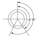
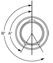
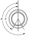
A Keyway Degree B Keyway Degree A 150 210 B 75 210 C 95 230 D 140 275 E 75 275 F 95 210 STEP 6: SELECT MODIFIER
2M 803 - CRIMPAMPHENOL 2M SERIES 2M 803 BAYONET
EXAMPLE 1 2 3 4 5 6 2M803-003-07 NF 8-13 P N -501 SHELL STYLE PLATING SHELL STYLE CONTACT TYPE KEYING MODIFIER STEP 1: SELECT SHELL STYLE, PLUG OR RECEPTACLE
* Add “-501” to the suffix of Jam Nut version to include a Hex Nut instead of a Spanner Nut. See Step 6. Read Less STEP 2: SELECT CLASS

C = Aluminum/ Black Anodize (Non-Conductive) (RoHS) M = Aluminum/ Electroless Nickel (RoHS) NF = Aluminum/ Cadmium with Olive Drab Chromate MT = Aluminum/ Nickel-PTFE (Durmalon) (RoHS) Z1 = Stainless Steel/ Passivated ZM = Stainless Steel/ Electroless Nickel (RoHS) ZN = Aluminum/ Zinc-Nickel with Olive Drab Chromate ZNU = Aluminum/ Zinc-Nickel with Black Chromate (RoHS) Read Less STEP 3: SELECT LAYOUT

Contact Size Layout # of Contacts 23 20 20HD 16 12 5-3 3 3 6-1 1 1 6-4 4 4 6-6 6 6 6-7 7 7 6-23 3 3 7-1 1 1 7-10 10 10 7-25 5 5 8-2 2 2 8-13 13 13 8-28 8 8 8-200 6 4 2 9-4 4 4 9-19 19 19 9-200 6 4 2 9-201 10 8 2 9-210 10 10 10-2 2 2 10-5 5 5 10-26 26 26 10-200 13 12 1 10-201 6 4 2 10-202 10 8 2 12-2 2 2 12-3 3 3 12-7 7 7 12-37 37 37 12-200 8 6 2 12-201 12 10 2 12-220 20 20 14-5 5 5 14-12 12 12 14-55 55 55 14-235 35 35 15-7 7 7 15-14 14 14 15-85 85 85 LAYOUT BY NUMBER OF CONTACTS
Front face of pin inserts shown. (Sockets mirror image) Contacts 1 2
2M801 6-1 7-1 8-2 10-2 13-2 2M803 6-1 7-1 8-2 10-2 12-2 2M804 6-1 7-1 8-2 10-2 12-2 2M805 8-1 9-1 10-2 12-2 15-2 # of Contacts & Size 1#26 1#12 2#16 2#12 2#12 DWV Voltage (VAC) 1800 1800 1800 1800 1800 Contacts 3 4
2M801 5-3 6-23 13-3 6-4 9-4 2M803 5-3 6-23 12-3 6-4 9-4 2M804 5-3 6-23 12-3 6-4 9-4 2M805 N/A 8-23 15-3 8-4 11-4 # of Contacts & Size 3#23 3#20HD 3#12 4#23 4#16 DWV Voltage (VAC) 500 750 1800 500 1800 Contacts 5 6
2M801 7-25 10-5 16-5 6-6 8-200 2M803 7-25 10-5 14-5 6-6 8-200 2M804 7-25 10-5 14-5 6-6 8-200 2M805 9-25 12-5 18-5 8-6 10-200 # of Contacts & Size 5#20HD 5#16 5#12 6#23 4#23, 2#20 DWV Voltage (VAC) 750 1800 1800 500 1000 (#20), 500 (#23) Contacts 6 (Cont.) 7
2M801 9-200 10-201 6-7 13-7 17-7 2M803 9-200 10-201 6-7 12-7 NA 2M804 9-200 10-201 6-7 12-7 NA 2M805 11-200 12-201 8-7 15-7 19-7 # of Contacts & Size 4#23, 2#16 4#23, 2#12 7#23 7#16 7#12 DWV Voltage (VAC) 1800 (#16), 500 (#23) 1800 (#12), 500 (#23) 500 1800 1800 Contacts 8 10
2M801 8-28 13-200 7-10 9-201 9-210 10-202 2M803 8-28 13-200 7-10 9-201 9-210 10-202 2M804 8-28 13-200 7-10 9-201 9-210 10-202 2M805 10-28 15-200 9-10 11-201 11-210 12-202 # of Contacts & Size 8#20HD 6#23, 2#12 10#23 8#23, 2#20 10#20HD 8#23, 2#16 DWV Voltage (VAC) 750 1800(#12), 500 (#23) 500 1000 (#700), 500 (#23) 750 1800 (#16), 500 (#23) Contacts 12 13
2M801 16-12 21-12 13-201 8-13 10-200 2M803 14-12 NA 12-201 8-13 10-200 2M804 14-12 NA 12-201 8-13 10-200 2M805 18-12 23-12 15-201 10-13 12-200 # of Contacts & Size 12#16 12#12 10#23, 2#12 13#23 12#23, 1#12 DWV Voltage (VAC) 1800 500 750 1800 500 Contacts 14 19 20 22 26
2M801 17-14 9-19 13-220 21-22 10-26 2M803 NA 9-19 12-220 NA 10-26 2M804 NA 9-19 12-220 NA 10-26 2M805 19-24 11-19 15-220 23-22 12-26 # of Contacts & Size 14#16 19#23 20#20HD 22#16 26#23 DWV Voltage (VAC) 1800 500 750 1800 500 Contacts 35 37 41 55 69
2M801 16-235 13-37 17-241 16-55 21-269 2M803 14-235 12-37 NA 14-55 NA 2M804 14-235 12-37 NA 14-55 NA 2M805 18-235 15-37 19-241 18-55 23-269 # of Contacts & Size 35#20HD 37#23 41#20HD 55#23 69#20HD DWV Voltage (VAC) 750 500 750 500 750 Contacts 85 130
2M801 17-85 21-130 2M803 NA NA 2M804 15-85 NA 2M805 19-85 23-130 # of Contacts & Size 85#23 130#23 DWV Voltage (VAC) 500 500 Read Less STEP 4: SELECT CONTACT
STEP 5: SELECT KEYING

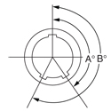
A Keyway Degree B Keyway Degree N 150 210 X 75 210 Y 95 230 Z 140 275 Read Less STEP 6: SELECT MODIFIER
2M 804 - CRIMPAMPHENOL 2M SERIES 2M 804 PUSH-PULL
EXAMPLE 1 2 3 4 5 6 2M804-003-07 NF 8-13 P A -501 SHELL STYLE PLATING SHELL STYLE CONTACT TYPE KEYING MODIFIER STEP 1: SELECT SHELL STYLE, PLUG OR RECEPTACLE
* Add “-501” to the suffix of Jam Nut version to include a Hex Nut instead of a Spanner Nut. See Step 6. Read Less STEP 2: SELECT CLASS
 C = Aluminum/ Black Anodize (Non-Conductive) (RoHS) M = Aluminum/ Electroless Nickel (RoHS) NF = Aluminum/ Cadmium with Olive Drab Chromate MT = Aluminum/ Nickel-PTFE (Durmalon) (RoHS) Z1 = Stainless Steel/ Passivated ZM = Stainless Steel/ Electroless Nickel (RoHS) ZN = Aluminum/ Zinc-Nickel with Olive Drab Chromate ZNU = Aluminum/ Zinc-Nickel with Black Chromate (RoHS) Read Less STEP 3: SELECT LAYOUT

Contact Size Layout # of Contacts 23 20 20HD 16 12 5-3 3 3 6-1 1 1 6-4 4 4 6-6 6 6 6-7 7 7 6-23 3 3 7-1 1 1 7-10 10 10 7-25 5 5 8-2 2 2 8-13 13 13 8-28 8 8 8-200 6 4 2 9-4 4 4 9-19 19 19 9-200 6 4 2 9-201 10 8 2 9-210 10 10 10-2 2 2 10-5 5 5 10-26 26 26 10-200 13 12 1 10-201 6 4 2 10-202 10 8 2 12-2 2 2 12-3 3 3 12-7 7 7 12-37 37 37 12-200 8 6 2 12-201 12 10 2 12-220 20 20 14-5 5 5 14-12 12 12 14-55 55 55 14-235 35 35 15-7 7 7 15-14 14 14 15-85 85 85 LAYOUT BY NUMBER OF CONTACTS Front face of pin inserts shown. (Sockets mirror image) Contacts 1 2
2M801 6-1 7-1 8-2 10-2 13-2 2M803 6-1 7-1 8-2 10-2 12-2 2M804 6-1 7-1 8-2 10-2 12-2 2M805 8-1 9-1 10-2 12-2 15-2 # of Contacts & Size 1#26 1#12 2#16 2#12 2#12 DWV Voltage (VAC) 1800 1800 1800 1800 1800 Contacts 3 4
2M801 5-3 6-23 13-3 6-4 9-4 2M803 5-3 6-23 12-3 6-4 9-4 2M804 5-3 6-23 12-3 6-4 9-4 2M805 N/A 8-23 15-3 8-4 11-4 # of Contacts & Size 3#23 3#20HD 3#12 4#23 4#16 DWV Voltage (VAC) 500 750 1800 500 1800 Contacts 5 6
2M801 7-25 10-5 16-5 6-6 8-200 2M803 7-25 10-5 14-5 6-6 8-200 2M804 7-25 10-5 14-5 6-6 8-200 2M805 9-25 12-5 18-5 8-6 10-200 # of Contacts & Size 5#20HD 5#16 5#12 6#23 4#23, 2#20 DWV Voltage (VAC) 750 1800 1800 500 1000 (#20), 500 (#23) Contacts 6 (Cont.) 7
2M801 9-200 10-201 6-7 13-7 17-7 2M803 9-200 10-201 6-7 12-7 NA 2M804 9-200 10-201 6-7 12-7 NA 2M805 11-200 12-201 8-7 15-7 19-7 # of Contacts & Size 4#23, 2#16 4#23, 2#12 7#23 7#16 7#12 DWV Voltage (VAC) 1800 (#16), 500 (#23) 1800 (#12), 500 (#23) 500 1800 1800 Contacts 8 10
2M801 8-28 13-200 7-10 9-201 9-210 10-202 2M803 8-28 13-200 7-10 9-201 9-210 10-202 2M804 8-28 13-200 7-10 9-201 9-210 10-202 2M805 10-28 15-200 9-10 11-201 11-210 12-202 # of Contacts & Size 8#20HD 6#23, 2#12 10#23 8#23, 2#20 10#20HD 8#23, 2#16 DWV Voltage (VAC) 750 1800(#12), 500 (#23) 500 1000 (#700), 500 (#23) 750 1800 (#16), 500 (#23) Contacts 12 13
2M801 16-12 21-12 13-201 8-13 10-200 2M803 14-12 NA 12-201 8-13 10-200 2M804 14-12 NA 12-201 8-13 10-200 2M805 18-12 23-12 15-201 10-13 12-200 # of Contacts & Size 12#16 12#12 10#23, 2#12 13#23 12#23, 1#12 DWV Voltage (VAC) 1800 500 750 1800 500 Contacts 14 19 20 22 26
2M801 17-14 9-19 13-220 21-22 10-26 2M803 NA 9-19 12-220 NA 10-26 2M804 NA 9-19 12-220 NA 10-26 2M805 19-24 11-19 15-220 23-22 12-26 # of Contacts & Size 14#16 19#23 20#20HD 22#16 26#23 DWV Voltage (VAC) 1800 500 750 1800 500 Contacts 35 37 41 55 69
2M801 16-235 13-37 17-241 16-55 21-269 2M803 14-235 12-37 NA 14-55 NA 2M804 14-235 12-37 NA 14-55 NA 2M805 18-235 15-37 19-241 18-55 23-269 # of Contacts & Size 35#20HD 37#23 41#20HD 55#23 69#20HD DWV Voltage (VAC) 750 500 750 500 750 Contacts 85 130
2M801 17-85 21-130 2M803 NA NA 2M804 15-85 NA 2M805 19-85 23-130 # of Contacts & Size 85#23 130#23 DWV Voltage (VAC) 500 500 Read Less STEP 4: SELECT CONTACT
STEP 5: SELECT KEYING

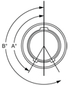
A Keyway Degree B Keyway Degree Omit For Normal Single Master Keyway A 150 210 B 75 210 C 95 230 D 140 275 Read Less STEP 6: SELECT MODIFIER*
2M 805 - CRIMPAMPHENOL 2M SERIES 2M 805 TRI-START THREADED
EXAMPLE 1 2 3 4 5 6 2M805-003-07 NF 8-23 P A -501 SHELL STYLE PLATING SHELL STYLE CONTACT TYPE KEYING MODIFIER STEP 1: SELECT SHELL STYLE, PLUG OR RECEPTACLE
* Add “-501” to the suffix of Jam Nut version to include a Hex Nut instead of a Spanner Nut. See Step 6. Read Less STEP 2: SELECT CLASS
 C = Aluminum/ Black Anodize (Non-Conductive) (RoHS) M = Aluminum/ Electroless Nickel (RoHS) NF = Aluminum/ Cadmium with Olive Drab Chromate MT = Aluminum/ Nickel-PTFE (Durmalon) (RoHS) Z1 = Stainless Steel/ Passivated ZM = Stainless Steel/ Electroless Nickel (RoHS) ZN = Aluminum/ Zinc-Nickel with Olive Drab Chromate ZNU = Aluminum/ Zinc-Nickel with Black Chromate (RoHS) Read Less STEP 3: SELECT LAYOUT

Contact Size Layout # of Contacts 23 20 20HD 16 12 8-1 1 1 8-4 4 4 8-6 6 6 8-7 7 7 8-23 3 3 9-1 1 1 9-10 10 10 9-25 5 5 10-2 2 2 10-13 13 13 10-28 8 8 10-200 6 4 2 11-4 4 4 11-19 19 19 11-200 6 4 2 11-201 10 8 2 11-210 10 10 12-2 2 2 12-5 5 5 12-26 26 26 12-200 13 12 1 12-201 6 4 2 12-202 10 8 2 15-2 2 2 15-3 3 3 15-7 7 7 15-37 37 37 15-200 8 6 2 15-201 12 10 2 15-220 20 20 18-5 5 5 18-12 12 12 18-55 55 55 18-235 35 35 19-7 7 7 19-14 14 14 19-85 85 85 19-241 41 41 23-12 12 12 23-22 22 22 23-130 130 130 23-269 69 69 LAYOUT BY NUMBER OF CONTACTS Front face of pin inserts shown. (Sockets mirror image) Contacts 1 2
2M801 6-1 7-1 8-2 10-2 13-2 2M803 6-1 7-1 8-2 10-2 12-2 2M804 6-1 7-1 8-2 10-2 12-2 2M805 8-1 9-1 10-2 12-2 15-2 # of Contacts & Size 1#26 1#12 2#16 2#12 2#12 DWV Voltage (VAC) 1800 1800 1800 1800 1800 Contacts 3 4
2M801 5-3 6-23 13-3 6-4 9-4 2M803 5-3 6-23 12-3 6-4 9-4 2M804 5-3 6-23 12-3 6-4 9-4 2M805 N/A 8-23 15-3 8-4 11-4 # of Contacts & Size 3#23 3#20HD 3#12 4#23 4#16 DWV Voltage (VAC) 500 750 1800 500 1800 Contacts 5 6
2M801 7-25 10-5 16-5 6-6 8-200 2M803 7-25 10-5 14-5 6-6 8-200 2M804 7-25 10-5 14-5 6-6 8-200 2M805 9-25 12-5 18-5 8-6 10-200 # of Contacts & Size 5#20HD 5#16 5#12 6#23 4#23, 2#20 DWV Voltage (VAC) 750 1800 1800 500 1000 (#20), 500 (#23) Contacts 6 (Cont.) 7
2M801 9-200 10-201 6-7 13-7 17-7 2M803 9-200 10-201 6-7 12-7 NA 2M804 9-200 10-201 6-7 12-7 NA 2M805 11-200 12-201 8-7 15-7 19-7 # of Contacts & Size 4#23, 2#16 4#23, 2#12 7#23 7#16 7#12 DWV Voltage (VAC) 1800 (#16), 500 (#23) 1800 (#12), 500 (#23) 500 1800 1800 Contacts 8 10
2M801 8-28 13-200 7-10 9-201 9-210 10-202 2M803 8-28 13-200 7-10 9-201 9-210 10-202 2M804 8-28 13-200 7-10 9-201 9-210 10-202 2M805 10-28 15-200 9-10 11-201 11-210 12-202 # of Contacts & Size 8#20HD 6#23, 2#12 10#23 8#23, 2#20 10#20HD 8#23, 2#16 DWV Voltage (VAC) 750 1800(#12), 500 (#23) 500 1000 (#700), 500 (#23) 750 1800 (#16), 500 (#23) Contacts 12 13
2M801 16-12 21-12 13-201 8-13 10-200 2M803 14-12 NA 12-201 8-13 10-200 2M804 14-12 NA 12-201 8-13 10-200 2M805 18-12 23-12 15-201 10-13 12-200 # of Contacts & Size 12#16 12#12 10#23, 2#12 13#23 12#23, 1#12 DWV Voltage (VAC) 1800 500 750 1800 500 Contacts 14 19 20 22 26
2M801 17-14 9-19 13-220 21-22 10-26 2M803 NA 9-19 12-220 NA 10-26 2M804 NA 9-19 12-220 NA 10-26 2M805 19-24 11-19 15-220 23-22 12-26 # of Contacts & Size 14#16 19#23 20#20HD 22#16 26#23 DWV Voltage (VAC) 1800 500 750 1800 500 Contacts 35 37 41 55 69
2M801 16-235 13-37 17-241 16-55 21-269 2M803 14-235 12-37 NA 14-55 NA 2M804 14-235 12-37 NA 14-55 NA 2M805 18-235 15-37 19-241 18-55 23-269 # of Contacts & Size 35#20HD 37#23 41#20HD 55#23 69#20HD DWV Voltage (VAC) 750 500 750 500 750 Contacts 85 130
2M801 17-85 21-130 2M803 NA NA 2M804 15-85 NA 2M805 19-85 23-130 # of Contacts & Size 85#23 130#23 DWV Voltage (VAC) 500 500 Read Less STEP 4: SELECT CONTACT
STEP 5: SELECT KEYING

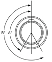
A Keyway Degree B Keyway Degree A 150 210 B 75 210 C 95 230 D 140 275 Read Less STEP 6: SELECT MODIFIER*
2M 801 - PCBAMPHENOL 2M SERIES 2M 801 DUAL START ACME - PCB RECEPTACLE
EXAMPLE 1 2 3 4 5 6 2M801-033-07 NF 6-7 P A -501 SHELL STYLE SERVICE CLASS SHELL SIZE CONTACT TYPE KEYING MODIFIER STEP 1: SELECT SHELL STYLE, PLUG OR RECEPTACLE

Square flange with Solder Cup or PCB Termination with Epoxy Potting
Jam Nut for Solder Cup or PCB Termination with Epoxy Potting
Jam Nut with Right Angle PCB termination.
Square flange with Solder Cup or PCB Termination with Special Sealing for Open Face (unmated) Water Immersion Requirements. 100% Leak Tested. To maintain a helium leak rate of 1-10-4 cc/sec. pressure differential from -55°C to 150° C.
Jam Nut with Solder Cup or PCB Termination with Special Sealing for Open Face (unmated) Water Immersion Requirements. 100% Leak Tested. To maintain a helium leak rate of 1-10-4 cc/sec. pressure differential from -55°C to 150° C.
Read Less STEP 2: SELECT CLASS
 C = Aluminum/ Black Anodize (Non-Conductive) (RoHS) M = Aluminum/ Electroless Nickel (RoHS) NF = Aluminum/ Cadmium with Olive Drab Chromate MT = Aluminum/ Nickel-PTFE (Durmalon) (RoHS) Z1 = Stainless Steel/ Passivated ZM = Stainless Steel/ Electroless Nickel (RoHS) ZN = Aluminum/ Zinc-Nickel with Olive Drab Chromate ZNU = Aluminum/ Zinc-Nickel with Black Chromate (RoHS) Read Less STEP 3: SELECT LAYOUT

Contact Size Layout # of Contacts 23 20 20HD 16 12 5-3‡ 3 3 6-1 1 1 6-4‡ 4 4 6-6 6 6 6-7‡ 7 7 6-23 3 3 7-1 1 1 7-10‡ 10 10 7-25 5 5 8-2‡ 2 2 8-13‡ 13 13 8-28 8 8 8-200 6 4 2 9-4 4 4 9-19‡ 19 19 9-200 6 4 2 9-201 10 8 2 9-210 10 10 10-2 2 2 10-5 5 5 10-26 26 26 10-200 13 12 1 10-201 6 4 2 10-202 10 8 2 13-2 2 2 13-3 3 3 13-7 7 7 13-37 37 37 13-200 8 6 2 13-201 12 10 2 13-220 20 20 16-5 5 5 16-12 12 12 16-55 55 55 16-235 35 35 17-7 7 7 17-14 14 14 17-85 85 85 17-241 41 41 21-12 12 12 21-22 22 22 21-130 130 130 21-269 69 69 ‡ 2M801-023-07 right angle PCB layout LAYOUT BY NUMBER OF CONTACTS
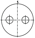
Front face of pin inserts shown. (Sockets mirror image) Contacts 1 2
2M801 6-1 7-1 8-2 10-2 13-2 2M803 6-1 7-1 8-2 10-2 12-2 2M804 6-1 7-1 8-2 10-2 12-2 2M805 8-1 9-1 10-2 12-2 15-2 # of Contacts & Size 1#26 1#12 2#16 2#12 2#12 DWV Voltage (VAC) 1800 1800 1800 1800 1800 Contacts 3 4
2M801 6-1 7-1 8-2 10-2 13-2 2M803 6-1 7-1 8-2 10-2 12-2 2M804 6-1 7-1 8-2 10-2 12-2 2M805 8-1 9-1 10-2 12-2 15-2 # of Contacts & Size 1#26 1#12 2#16 2#12 2#12 DWV Voltage (VAC) 1800 1800 1800 1800 1800 Contacts 3 4
2M801 5-3 6-23 13-3 6-4 9-4 2M803 5-3 6-23 12-3 6-4 9-4 2M804 5-3 6-23 12-3 6-4 9-4 2M805 N/A 8-23 15-3 8-4 11-4 # of Contacts & Size 3#23 3#20HD 3#12 4#23 4#16 DWV Voltage (VAC) 500 750 1800 500 1800 Contacts 5 6
2M801 7-25 10-5 16-5 6-6 8-200 2M803 7-25 10-5 14-5 6-6 8-200 2M804 7-25 10-5 14-5 6-6 8-200 2M805 9-25 12-5 18-5 8-6 10-200 # of Contacts & Size 5#20HD 5#16 5#12 6#23 4#23, 2#20 DWV Voltage (VAC) 750 1800 1800 500 1000 (#20), 500 (#23) Contacts 6 (Cont.) 7
2M801 9-200 10-201 6-7 13-7 17-7 2M803 9-200 10-201 6-7 12-7 NA 2M804 9-200 10-201 6-7 12-7 NA 2M805 11-200 12-201 8-7 15-7 19-7 # of Contacts & Size 4#23, 2#16 4#23, 2#12 7#23 7#16 7#12 DWV Voltage (VAC) 1800 (#16), 500 (#23) 1800 (#12), 500 (#23) 500 1800 1800 Contacts 8 10
2M801 8-28 13-200 7-10 9-201 9-210 10-202 2M803 8-28 13-200 7-10 9-201 9-210 10-202 2M804 8-28 13-200 7-10 9-201 9-210 10-202 2M805 10-28 15-200 9-10 11-201 11-210 12-202 # of Contacts & Size 8#20HD 6#23, 2#12 10#23 8#23, 2#20 10#20HD 8#23, 2#16 DWV Voltage (VAC) 750 1800(#12), 500 (#23) 500 1000 (#700), 500 (#23) 750 1800 (#16), 500 (#23) Contacts 12 13
2M801 16-12 21-12 13-201 8-13 10-200 2M803 14-12 NA 12-201 8-13 10-200 2M804 14-12 NA 12-201 8-13 10-200 2M805 18-12 23-12 15-201 10-13 12-200 # of Contacts & Size 12#16 12#12 10#23, 2#12 13#23 12#23, 1#12 DWV Voltage (VAC) 1800 500 750 1800 500 Contacts 14 19 20 22 26
2M801 17-14 9-19 13-220 21-22 10-26 2M803 NA 9-19 12-220 NA 10-26 2M804 NA 9-19 12-220 NA 10-26 2M805 19-24 11-19 15-220 23-22 12-26 # of Contacts & Size 14#16 19#23 20#20HD 22#16 26#23 DWV Voltage (VAC) 1800 500 750 1800 500 Contacts 35 37 41 55 69
2M801 16-235 13-37 17-241 16-55 21-269 2M803 14-235 12-37 NA 14-55 NA 2M804 14-235 12-37 NA 14-55 NA 2M805 18-235 15-37 19-241 18-55 23-269 # of Contacts & Size 35#20HD 37#23 41#20HD 55#23 69#20HD DWV Voltage (VAC) 750 500 750 500 750 Contacts 85 130
2M801 17-85 21-130 2M803 NA NA 2M804 15-85 NA 2M805 19-85 23-130 # of Contacts & Size 85#23 130#23 DWV Voltage (VAC) 500 500 AMPHENOL 2M SERIES STRAIGHT PCB FOOTPRINTS
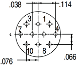
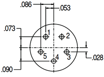
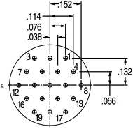
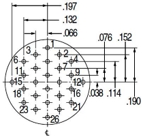
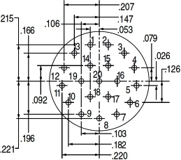
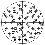
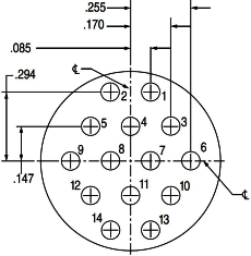
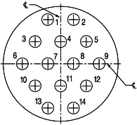
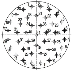
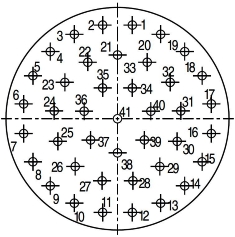
Socket inserts are a mirror image of pin side. Socket side shown for cavity locations only, reference pin side for dimensions. Insert Arrangement Pin Connector Socket Connector
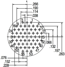
X Y Pin No. In. MM In. MM 1 -.053 -1.35 .301 7.65 2 .053 1.35 .301 7.65 3 .153 3.89 .264 6.71 4 .234 5.94 .196 4.98 5 .287 7.29 .104 2.64 6 .305 7.75 .000 0.00 7 .287 7.29 -.104 -2.64 8 .234 5.94 -.196 -4.98 9 .153 3.89 -.264 -6.71 10 .053 1.35 -.301 -7.65 11 -.053 -1.35 -.301 -7.65 12 -.153 -3.89 -.264 -6.71 13 -.234 -5.94 -.196 -4.98 14 -.287 -7.29 -.104 -2.64 15 -.305 -7.75 .000 0.00 16 -.287 7.29 .104 2.64 17 -.234 -5.94 .196 4.98 18 -.153 -3.89 .264 6.71 19 .000 0.00 .209 5.31 20 .100 2.54 .172 4.37 21 .181 4.60 .104 2.64 22 .199 5.05 .000 0.00 23 .181 4.60 -.104 -2.64 24 .100 2.54 -.172 -4.37 25 .000 0.00 -.209 -5.31 26 -.100 -2.54 -.172 -4.37 27 -.181 -4.60 -.104 -2.64 28 -.199 -5.05 .000 0.00 29 -.181 -4.60 .104 2.64 30 -.100 -2.54 .172 4.37 31 -.053 -1.35 .073 1.85 32 .053 1.35 .073 1.85 33 .086 2.18 -.028 -0.71 34 .000 0.00 -.090 -2.29 35 -.086 -2.18 -.028 -0.71 Insert Arrangement Pin Connector Socket Connector
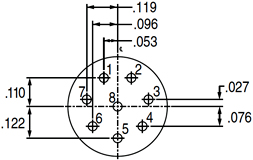
X Y Pin No. In. MM In. MM 1 -.053 -1.35 .335 8.51 2 .053 1.35 .335 8.51 3 .154 3.91 .302 7.67 4 .240 6.10 .240 6.10 5 .302 7.67 .154 3.91 6 .335 8.51 .053 1.35 7 .335 8.51 -.053 -1.35 8 .302 7.67 -.154 -3.91 9 .240 6.10 -.240 -6.10 10 .154 3.91 -.302 -7.67 11 .053 1.35 -.335 -8.51 12 -.053 -1.35 -.335 -6.51 13 -.154 -3.91 -.302 -7.67 14 -.240 -6.10 -.240 -6.10 15 -.302 -7.67 -.154 -3.91 16 -.335 -8.51 -.053 -1.35 17 -.335 -8.51 .053 1.35 18 -.302 -7.67 .154 3.91 19 -.240 -6.10 .240 6.10 20 -.154 -3.91 .302 7.67 21 .000 0.00 .228 5.79 22 .106 2.69 .202 5.13 23 .188 4.78 .130 3.30 24 .226 5.74 .028 0.71 25 .213 5.41 -.081 -2.06 26 .151 3.84 -.171 -4.34 27 .055 1.40 -.222 -5.64 28 -.055 -1.40 -.222 -5.64 29 -.151 -3.84 -.171 -4.34 30 -.213 -5.41 -.081 -2.06 31 -.226 -5.74 .028 0.71 32 -.188 -4.78 .130 3.30 33 -.106 -2.69 .202 5.13 34 -.053 -1.35 .110 2.79 35 .053 1.35 .110 2.79 36 .119 3.02 .027 0.69 37 .096 2.44 -.076 -1.93 38 .000 0.00 -.122 -3.10 39 -.096 -2.44 -.076 -1.93 40 -.119 -3.02 .027 0.69 41 .000 0.00 .000 0.00 STEP 4: SELECT CONTACT
STEP 5: SELECT KEYING

A Keyway Degree B Keyway Degree A 150° 210° B 75° 210° C 95° 230° D 140° 275° E 75° 275° F 95° 210° STEP 6: SELECT MODIFIER*
2M 803 - PCBAMPHENOL 2M SERIES 2M 803 BAYONET - PCB RECEPTACLE
EXAMPLE 1 2 3 4 5 6 2M803-005-07 NF 8-13 P N -501 SHELL STYLE CLASS SHELL SIZE CONTACT TYPE KEYING MODIFIER STEP 1: SELECT SHELL STYLE, PLUG OR RECEPTACLE

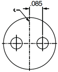
2-Hole Flange mount with Solder Cup or PCB Termination with Epoxy Potting
Jam Nut for Solder Cup or PCB Termination with Epoxy Potting
2-Hole Flange Mount with Solder Cup or PCB Termination with Special Sealing for Open Face (unmated) Water Immersion Requirements. 100% Leak Tested. To maintain a helium leak rate of 1-10-4 cc/sec. pressure differential from -55°C to 150° C.
Jam Nut with Solder Cup or PCB Termination with Special Sealing for Open Face (unmated) Water Immersion Requirements. 100% Leak Tested. To maintain a helium leak rate of 1-10-4 cc/sec. pressure differential from -55°C to 150° C. * Add “-501” to the suffix of Jam Nut version to include a Hex Nut instead of a Spanner Nut. See Step 6. Read Less STEP 2: SELECT CLASS
 C = Aluminum/ Black Anodize (Non-Conductive) (RoHS) M = Aluminum/ Electroless Nickel (RoHS) NF = Aluminum/ Cadmium with Olive Drab Chromate MT = Aluminum/ Nickel-PTFE (Durmalon) (RoHS) Z1 = Stainless Steel/ Passivated ZM = Stainless Steel/ Electroless Nickel (RoHS) ZN = Aluminum/ Zinc-Nickel with Olive Drab Chromate ZNU = Aluminum/ Zinc-Nickel with Black Chromate (RoHS) Read Less STEP 3: SELECT LAYOUT

Contact Size Layout # of Contacts 23 20 20HD 16 12 5-3 3 3 6-1 1 1 6-4 4 4 6-6 6 6 6-7 7 7 6-23 3 3 7-1 1 1 7-10 10 10 7-25 5 5 8-2 2 2 8-13 13 13 8-28 8 8 8-200 6 4 2 9-4 4 4 9-19 19 19 9-200 6 4 2 9-201 10 8 2 9-210 10 10 10-2 2 2 10-5 5 5 10-26 26 26 10-200 13 12 1 10-201 6 4 2 10-202 10 8 2 13-2 2 2 13-3 3 3 13-7 7 7 13-37 37 37 13-200 8 6 2 13-201 12 10 2 13-220 20 20 16-5 5 5 16-12 12 12 16-55 55 55 16-235 35 35 17-7 7 7 17-14 14 14 17-85 85 85 17-241 41 41 21-12 12 12 21-22 22 22 21-130 130 130 21-269 69 69 LAYOUT BY NUMBER OF CONTACTS
Front face of pin inserts shown. (Sockets mirror image) Contacts 1 2
2M801 6-1 7-1 8-2 10-2 13-2 2M803 6-1 7-1 8-2 10-2 12-2 2M804 6-1 7-1 8-2 10-2 12-2 2M805 8-1 9-1 10-2 12-2 15-2 # of Contacts & Size 1#26 1#12 2#16 2#12 2#12 DWV Voltage (VAC) 1800 1800 1800 1800 1800 Contacts 3 4
2M801 5-3 6-23 13-3 6-4 9-4 2M803 5-3 6-23 12-3 6-4 9-4 2M804 5-3 6-23 12-3 6-4 9-4 2M805 N/A 8-23 15-3 8-4 11-4 # of Contacts & Size 3#23 3#20HD 3#12 4#23 4#16 DWV Voltage (VAC) 500 750 1800 500 1800 Contacts 5 6
2M801 7-25 10-5 16-5 6-6 8-200 2M803 7-25 10-5 14-5 6-6 8-200 2M804 7-25 10-5 14-5 6-6 8-200 2M805 9-25 12-5 18-5 8-6 10-200 # of Contacts & Size 5#20HD 5#16 5#12 6#23 4#23, 2#20 DWV Voltage (VAC) 750 1800 1800 500 1000 (#20), 500 (#23) Contacts 6 (Cont.) 7
2M801 9-200 10-201 6-7 13-7 17-7 2M803 9-200 10-201 6-7 12-7 NA 2M804 9-200 10-201 6-7 12-7 NA 2M805 11-200 12-201 8-7 15-7 19-7 # of Contacts & Size 4#23, 2#16 4#23, 2#12 7#23 7#16 7#12 DWV Voltage (VAC) 1800 (#16), 500 (#23) 1800 (#12), 500 (#23) 500 1800 1800 Contacts 8 10
2M801 8-28 13-200 7-10 9-201 9-210 10-202 2M803 8-28 13-200 7-10 9-201 9-210 10-202 2M804 8-28 13-200 7-10 9-201 9-210 10-202 2M805 10-28 15-200 9-10 11-201 11-210 12-202 # of Contacts & Size 8#20HD 6#23, 2#12 10#23 8#23, 2#20 10#20HD 8#23, 2#16 DWV Voltage (VAC) 750 1800(#12), 500 (#23) 500 1000 (#700), 500 (#23) 750 1800 (#16), 500 (#23) Contacts 12 13
2M801 16-12 21-12 13-201 8-13 10-200 2M803 14-12 NA 12-201 8-13 10-200 2M804 14-12 NA 12-201 8-13 10-200 2M805 18-12 23-12 15-201 10-13 12-200 # of Contacts & Size 12#16 12#12 10#23, 2#12 13#23 12#23, 1#12 DWV Voltage (VAC) 1800 500 750 1800 500 Contacts 14 19 20 22 26
2M801 17-14 9-19 13-220 21-22 10-26 2M803 NA 9-19 12-220 NA 10-26 2M804 NA 9-19 12-220 NA 10-26 2M805 19-24 11-19 15-220 23-22 12-26 # of Contacts & Size 14#16 19#23 20#20HD 22#16 26#23 DWV Voltage (VAC) 1800 500 750 1800 500 Contacts 35 37 41 55 69
2M801 16-235 13-37 17-241 16-55 21-269 2M803 14-235 12-37 NA 14-55 NA 2M804 14-235 12-37 NA 14-55 NA 2M805 18-235 15-37 19-241 18-55 23-269 # of Contacts & Size 35#20HD 37#23 41#20HD 55#23 69#20HD DWV Voltage (VAC) 750 500 750 500 750 Contacts 85 130
2M801 17-85 21-130 2M803 NA NA 2M804 15-85 NA 2M805 19-85 23-130 # of Contacts & Size 85#23 130#23 DWV Voltage (VAC) 500 500 AMPHENOL 2M SERIES STRAIGHT PCB FOOTPRINTS
Socket inserts are a mirror image of pin side. Socket side shown for cavity locations only, reference pin side for dimensions. Insert Arrangement Pin Connector Socket Connector
X Y Pin No. In. MM In. MM 1 -.053 -1.35 .301 7.65 2 .053 1.35 .301 7.65 3 .153 3.89 .264 6.71 4 .234 5.94 .196 4.98 5 .287 7.29 .104 2.64 6 .305 7.75 .000 0.00 7 .287 7.29 -.104 -2.64 8 .234 5.94 -.196 -4.98 9 .153 3.89 -.264 -6.71 10 .053 1.35 -.301 -7.65 11 -.053 -1.35 -.301 -7.65 12 -.153 -3.89 -.264 -6.71 13 -.234 -5.94 -.196 -4.98 14 -.287 -7.29 -.104 -2.64 15 -.305 -7.75 .000 0.00 16 -.287 7.29 .104 2.64 17 -.234 -5.94 .196 4.98 18 -.153 -3.89 .264 6.71 19 .000 0.00 .209 5.31 20 .100 2.54 .172 4.37 21 .181 4.60 .104 2.64 22 .199 5.05 .000 0.00 23 .181 4.60 -.104 -2.64 24 .100 2.54 -.172 -4.37 25 .000 0.00 -.209 -5.31 26 -.100 -2.54 -.172 -4.37 27 -.181 -4.60 -.104 -2.64 28 -.199 -5.05 .000 0.00 29 -.181 -4.60 .104 2.64 30 -.100 -2.54 .172 4.37 31 -.053 -1.35 .073 1.85 32 .053 1.35 .073 1.85 33 .086 2.18 -.028 -0.71 34 .000 0.00 -.090 -2.29 35 -.086 -2.18 -.028 -0.71 Insert Arrangement Pin Connector Socket Connector
X Y Pin No. In. MM In. MM 1 -.053 -1.35 .335 8.51 2 .053 1.35 .335 8.51 3 .154 3.91 .302 7.67 4 .240 6.10 .240 6.10 5 .302 7.67 .154 3.91 6 .335 8.51 .053 1.35 7 .335 8.51 -.053 -1.35 8 .302 7.67 -.154 -3.91 9 .240 6.10 -.240 -6.10 10 .154 3.91 -.302 -7.67 11 .053 1.35 -.335 -8.51 12 -.053 -1.35 -.335 -6.51 13 -.154 -3.91 -.302 -7.67 14 -.240 -6.10 -.240 -6.10 15 -.302 -7.67 -.154 -3.91 16 -.335 -8.51 -.053 -1.35 17 -.335 -8.51 .053 1.35 18 -.302 -7.67 .154 3.91 19 -.240 -6.10 .240 6.10 20 -.154 -3.91 .302 7.67 21 .000 0.00 .228 5.79 22 .106 2.69 .202 5.13 23 .188 4.78 .130 3.30 24 .226 5.74 .028 0.71 25 .213 5.41 -.081 -2.06 26 .151 3.84 -.171 -4.34 27 .055 1.40 -.222 -5.64 28 -.055 -1.40 -.222 -5.64 29 -.151 -3.84 -.171 -4.34 30 -.213 -5.41 -.081 -2.06 31 -.226 -5.74 .028 0.71 32 -.188 -4.78 .130 3.30 33 -.106 -2.69 .202 5.13 34 -.053 -1.35 .110 2.79 35 .053 1.35 .110 2.79 36 .119 3.02 .027 0.69 37 .096 2.44 -.076 -1.93 38 .000 0.00 -.122 -3.10 39 -.096 -2.44 -.076 -1.93 40 -.119 -3.02 .027 0.69 41 .000 0.00 .000 0.00 STEP 4: SELECT CONTACT
STEP 5: SELECT KEYING

A Keyway Degree B Keyway Degree N 150° 210° X 75° 210° Y 95° 230° Z 140° 275° STEP 6: SELECT MODIFIER*
2M 804 - PCBAMPHENOL 2M SERIES 2M 804 PUSH-PULL QUICK DISCONNECT - PCB
EXAMPLE 1 2 3 4 5 6 2M804-005-07 NF 8-13 P A -501 SHELL STYLE CLASS SHELL SIZE CONTACT TYPE KEYING MODIFIER STEP 1: SELECT SHELL STYLE, PLUG OR RECEPTACLE

Solder Cup or PCB Termination with Standard Epoxy Potting
Jam Nut with Solder Cup or PCB Termination with Epoxy Potting
Solder Cup or PCB Termination with Special Sealing for Open Face (unmated) Water Immersion Requirements. 100% Leak Tested. To maintain a helium leak rate of 1x10⁻⁴ cc/sec. pressure differential from -65°C to 150°C.
Jam nut with Solder Cup or PCB Termination with Special Sealing for Open Face (unmated) Water Immersion Requirements. 100% Leak Tested. To maintain a helium leak rate of 1x10⁻⁴ cc/sec. pressure differential from -65°C to 150°C. * Add “-501” to the suffix of Jam Nut version to include a Hex Nut instead of a Spanner Nut. See Step 6. Read Less STEP 2: SELECT SHELL STYLE
 C = Aluminum/ Black Anodize (Non-Conductive) (RoHS) M = Aluminum/ Electroless Nickel (RoHS) NF = Aluminum/ Cadmium with Olive Drab Chromate MT = Aluminum/ Nickel-PTFE (Durmalon) (RoHS) Z1 = Stainless Steel/ Passivated ZM = Stainless Steel/ Electroless Nickel (RoHS) ZN = Aluminum/ Zinc-Nickel with Olive Drab Chromate ZNU = Aluminum/ Zinc-Nickel with Black Chromate (RoHS) Read Less STEP 3: SELECT LAYOUT

Contact Size Layout # of Contacts 23 20 20HD 16 12 5-3 3 3 6-1 1 1 6-4 4 4 6-6 6 6 6-7 7 7 6-23 3 3 7-1 1 1 7-10 10 10 7-25 5 5 8-2 2 2 8-13 13 13 8-28 8 8 8-200 6 4 2 9-4 4 4 9-19 19 19 9-200 6 4 2 9-201 10 8 2 9-210 10 10 10-2 2 2 10-5 5 5 10-26 26 26 10-200 13 12 1 10-201 6 4 2 10-202 10 8 2 13-2 2 2 13-3 3 3 13-7 7 7 13-37 37 37 13-200 8 6 2 13-201 12 10 2 13-220 20 20 16-5 5 5 16-12 12 12 16-55 55 55 16-235 35 35 17-7 7 7 17-14 14 14 17-85 85 85 17-241 41 41 21-12 12 12 21-22 22 22 21-130 130 130 21-269 69 69 LAYOUT BY NUMBER OF CONTACTS
Front face of pin inserts shown. (Sockets mirror image) Contacts 1 2
2M801 6-1 7-1 8-2 10-2 13-2 2M803 6-1 7-1 8-2 10-2 12-2 2M804 6-1 7-1 8-2 10-2 12-2 2M805 8-1 9-1 10-2 12-2 15-2 # of Contacts & Size 1#26 1#12 2#16 2#12 2#12 DWV Voltage (VAC) 1800 1800 1800 1800 1800 Contacts 3 4
2M801 5-3 6-23 13-3 6-4 9-4 2M803 5-3 6-23 12-3 6-4 9-4 2M804 5-3 6-23 12-3 6-4 9-4 2M805 N/A 8-23 15-3 8-4 11-4 # of Contacts & Size 3#23 3#20HD 3#12 4#23 4#16 DWV Voltage (VAC) 500 750 1800 500 1800 Contacts 5 6
2M801 7-25 10-5 16-5 6-6 8-200 2M803 7-25 10-5 14-5 6-6 8-200 2M804 7-25 10-5 14-5 6-6 8-200 2M805 9-25 12-5 18-5 8-6 10-200 # of Contacts & Size 5#20HD 5#16 5#12 6#23 4#23, 2#20 DWV Voltage (VAC) 750 1800 1800 500 1000 (#20), 500 (#23) Contacts 6 (Cont.) 7
2M801 9-200 10-201 6-7 13-7 17-7 2M803 9-200 10-201 6-7 12-7 NA 2M804 9-200 10-201 6-7 12-7 NA 2M805 11-200 12-201 8-7 15-7 19-7 # of Contacts & Size 4#23, 2#16 4#23, 2#12 7#23 7#16 7#12 DWV Voltage (VAC) 1800 (#16), 500 (#23) 1800 (#12), 500 (#23) 500 1800 1800 Contacts 8 10
2M801 8-28 13-200 7-10 9-201 9-210 10-202 2M803 8-28 13-200 7-10 9-201 9-210 10-202 2M804 8-28 13-200 7-10 9-201 9-210 10-202 2M805 10-28 15-200 9-10 11-201 11-210 12-202 # of Contacts & Size 8#20HD 6#23, 2#12 10#23 8#23, 2#20 10#20HD 8#23, 2#16 DWV Voltage (VAC) 750 1800(#12), 500 (#23) 500 1000 (#700), 500 (#23) 750 1800 (#16), 500 (#23) Contacts 12 13
2M801 16-12 21-12 13-201 8-13 10-200 2M803 14-12 NA 12-201 8-13 10-200 2M804 14-12 NA 12-201 8-13 10-200 2M805 18-12 23-12 15-201 10-13 12-200 # of Contacts & Size 12#16 12#12 10#23, 2#12 13#23 12#23, 1#12 DWV Voltage (VAC) 1800 500 750 1800 500 Contacts 14 19 20 22 26
2M801 17-14 9-19 13-220 21-22 10-26 2M803 NA 9-19 12-220 NA 10-26 2M804 NA 9-19 12-220 NA 10-26 2M805 19-24 11-19 15-220 23-22 12-26 # of Contacts & Size 14#16 19#23 20#20HD 22#16 26#23 DWV Voltage (VAC) 1800 500 750 1800 500 Contacts 35 37 41 55 69
2M801 16-235 13-37 17-241 16-55 21-269 2M803 14-235 12-37 NA 14-55 NA 2M804 14-235 12-37 NA 14-55 NA 2M805 18-235 15-37 19-241 18-55 23-269 # of Contacts & Size 35#20HD 37#23 41#20HD 55#23 69#20HD DWV Voltage (VAC) 750 500 750 500 750 Contacts 85 130
2M801 17-85 21-130 2M803 NA NA 2M804 15-85 NA 2M805 19-85 23-130 # of Contacts & Size 85#23 130#23 DWV Voltage (VAC) 500 500 AMPHENOL 2M SERIES STRAIGHT PCB FOOTPRINTS
Socket inserts are a mirror image of pin side. Socket side shown for cavity locations only, reference pin side for dimensions. Insert Arrangement Pin Connector Socket Connector
X Y Pin No. In. MM In. MM 1 -.053 -1.35 .301 7.65 2 .053 1.35 .301 7.65 3 .153 3.89 .264 6.71 4 .234 5.94 .196 4.98 5 .287 7.29 .104 2.64 6 .305 7.75 .000 0.00 7 .287 7.29 -.104 -2.64 8 .234 5.94 -.196 -4.98 9 .153 3.89 -.264 -6.71 10 .053 1.35 -.301 -7.65 11 -.053 -1.35 -.301 -7.65 12 -.153 -3.89 -.264 -6.71 13 -.234 -5.94 -.196 -4.98 14 -.287 -7.29 -.104 -2.64 15 -.305 -7.75 .000 0.00 16 -.287 7.29 .104 2.64 17 -.234 -5.94 .196 4.98 18 -.153 -3.89 .264 6.71 19 .000 0.00 .209 5.31 20 .100 2.54 .172 4.37 21 .181 4.60 .104 2.64 22 .199 5.05 .000 0.00 23 .181 4.60 -.104 -2.64 24 .100 2.54 -.172 -4.37 25 .000 0.00 -.209 -5.31 26 -.100 -2.54 -.172 -4.37 27 -.181 -4.60 -.104 -2.64 28 -.199 -5.05 .000 0.00 29 -.181 -4.60 .104 2.64 30 -.100 -2.54 .172 4.37 31 -.053 -1.35 .073 1.85 32 .053 1.35 .073 1.85 33 .086 2.18 -.028 -0.71 34 .000 0.00 -.090 -2.29 35 -.086 -2.18 -.028 -0.71 Insert Arrangement Pin Connector Socket Connector
X Y Pin No. In. MM In. MM 1 -.053 -1.35 .335 8.51 2 .053 1.35 .335 8.51 3 .154 3.91 .302 7.67 4 .240 6.10 .240 6.10 5 .302 7.67 .154 3.91 6 .335 8.51 .053 1.35 7 .335 8.51 -.053 -1.35 8 .302 7.67 -.154 -3.91 9 .240 6.10 -.240 -6.10 10 .154 3.91 -.302 -7.67 11 .053 1.35 -.335 -8.51 12 -.053 -1.35 -.335 -6.51 13 -.154 -3.91 -.302 -7.67 14 -.240 -6.10 -.240 -6.10 15 -.302 -7.67 -.154 -3.91 16 -.335 -8.51 -.053 -1.35 17 -.335 -8.51 .053 1.35 18 -.302 -7.67 .154 3.91 19 -.240 -6.10 .240 6.10 20 -.154 -3.91 .302 7.67 21 .000 0.00 .228 5.79 22 .106 2.69 .202 5.13 23 .188 4.78 .130 3.30 24 .226 5.74 .028 0.71 25 .213 5.41 -.081 -2.06 26 .151 3.84 -.171 -4.34 27 .055 1.40 -.222 -5.64 28 -.055 -1.40 -.222 -5.64 29 -.151 -3.84 -.171 -4.34 30 -.213 -5.41 -.081 -2.06 31 -.226 -5.74 .028 0.71 32 -.188 -4.78 .130 3.30 33 -.106 -2.69 .202 5.13 34 -.053 -1.35 .110 2.79 35 .053 1.35 .110 2.79 36 .119 3.02 .027 0.69 37 .096 2.44 -.076 -1.93 38 .000 0.00 -.122 -3.10 39 -.096 -2.44 -.076 -1.93 40 -.119 -3.02 .027 0.69 41 .000 0.00 .000 0.00 Read Less STEP 4: SELECT CONTACT
STEP 5: SELECT KEYING

A Keyway Degree B Keyway Degree N 150° 210° X 75° 210° Y 95° 230° Z 140° 275° STEP 6: SELECT MODIFIER*
2M 805 - PCBAMPHENOL 2M SERIES 2M 805 TRI-START THREADED COUPLING - PCB
EXAMPLE 1 2 3 4 5 6 2M805-005-07 NF 8-13 P A -501 SHELL STYLE CLASS SHELL SIZE CONTACT TYPE KEYING MODIFIER STEP 1: SELECT SHELL STYLE, PLUG OR RECEPTACLE

Square Flange with Solder Cup or PCB Termination with Standard Epoxy Potting
Jam Nut with Solder Cup or PCB Termination with Epoxy Potting
Square Flange with Solder Cup or PCB Termination with Special Sealing for Open Face (unmated) Water Immersion Requirements. 100% Leak Tested. To maintain a helium leak rate of 1x10⁻⁴ cc/sec. pressure differential from -65°C to 150°C.
Jam nut with Solder Cup or PCB Termination with Special Sealing for Open Face (unmated) Water Immersion Requirements. 100% Leak Tested. To maintain a helium leak rate of 1x10⁻⁴ cc/sec. pressure differential from -65°C to 150°C. * Add “-501” to the suffix of Jam Nut version to include a Hex Nut instead of a Spanner Nut. See Step 6. Read Less STEP 2: SELECT CLASS
 C = Aluminum/ Black Anodize (Non-Conductive) (RoHS) M = Aluminum/ Electroless Nickel (RoHS) NF = Aluminum/ Cadmium with Olive Drab Chromate MT = Aluminum/ Nickel-PTFE (Durmalon) (RoHS) Z1 = Stainless Steel/ Passivated ZM = Stainless Steel/ Electroless Nickel (RoHS) ZN = Aluminum/ Zinc-Nickel with Olive Drab Chromate ZNU = Aluminum/ Zinc-Nickel with Black Chromate (RoHS) Read Less STEP 3: SELECT LAYOUT

Contact Size Layout # of Contacts 23 20 20HD 16 12 5-3 3 3 6-1 1 1 6-4 4 4 6-6 6 6 6-7 7 7 6-23 3 3 7-1 1 1 7-10 10 10 7-25 5 5 8-2 2 2 8-13 13 13 8-28 8 8 8-200 6 4 2 9-4 4 4 9-19 19 19 9-200 6 4 2 9-201 10 8 2 9-210 10 10 10-2 2 2 10-5 5 5 10-26 26 26 10-200 13 12 1 10-201 6 4 2 10-202 10 8 2 13-2 2 2 13-3 3 3 13-7 7 7 13-37 37 37 13-200 8 6 2 13-201 12 10 2 13-220 20 20 16-5 5 5 16-12 12 12 16-55 55 55 16-235 35 35 17-7 7 7 17-14 14 14 17-85 85 85 17-241 41 41 21-12 12 12 21-22 22 22 21-130 130 130 21-269 69 69 LAYOUT BY NUMBER OF CONTACTS
Front face of pin inserts shown. (Sockets mirror image) Contacts 1 2
2M801 6-1 7-1 8-2 10-2 13-2 2M803 6-1 7-1 8-2 10-2 12-2 2M804 6-1 7-1 8-2 10-2 12-2 2M805 8-1 9-1 10-2 12-2 15-2 # of Contacts & Size 1#26 1#12 2#16 2#12 2#12 DWV Voltage (VAC) 1800 1800 1800 1800 1800 Contacts 3 4
2M801 5-3 6-23 13-3 6-4 9-4 2M803 5-3 6-23 12-3 6-4 9-4 2M804 5-3 6-23 12-3 6-4 9-4 2M805 N/A 8-23 15-3 8-4 11-4 # of Contacts & Size 3#23 3#20HD 3#12 4#23 4#16 DWV Voltage (VAC) 500 750 1800 500 1800 Contacts 5 6
2M801 7-25 10-5 16-5 6-6 8-200 2M803 7-25 10-5 14-5 6-6 8-200 2M804 7-25 10-5 14-5 6-6 8-200 2M805 9-25 12-5 18-5 8-6 10-200 # of Contacts & Size 5#20HD 5#16 5#12 6#23 4#23, 2#20 DWV Voltage (VAC) 750 1800 1800 500 1000 (#20), 500 (#23) Contacts 6 (Cont.) 7
2M801 9-200 10-201 6-7 13-7 17-7 2M803 9-200 10-201 6-7 12-7 NA 2M804 9-200 10-201 6-7 12-7 NA 2M805 11-200 12-201 8-7 15-7 19-7 # of Contacts & Size 4#23, 2#16 4#23, 2#12 7#23 7#16 7#12 DWV Voltage (VAC) 1800 (#16), 500 (#23) 1800 (#12), 500 (#23) 500 1800 1800 Contacts 8 10
2M801 8-28 13-200 7-10 9-201 9-210 10-202 2M803 8-28 13-200 7-10 9-201 9-210 10-202 2M804 8-28 13-200 7-10 9-201 9-210 10-202 2M805 10-28 15-200 9-10 11-201 11-210 12-202 # of Contacts & Size 8#20HD 6#23, 2#12 10#23 8#23, 2#20 10#20HD 8#23, 2#16 DWV Voltage (VAC) 750 1800(#12), 500 (#23) 500 1000 (#700), 500 (#23) 750 1800 (#16), 500 (#23) Contacts 12 13
2M801 16-12 21-12 13-201 8-13 10-200 2M803 14-12 NA 12-201 8-13 10-200 2M804 14-12 NA 12-201 8-13 10-200 2M805 18-12 23-12 15-201 10-13 12-200 # of Contacts & Size 12#16 12#12 10#23, 2#12 13#23 12#23, 1#12 DWV Voltage (VAC) 1800 500 750 1800 500 Contacts 14 19 20 22 26
2M801 17-14 9-19 13-220 21-22 10-26 2M803 NA 9-19 12-220 NA 10-26 2M804 NA 9-19 12-220 NA 10-26 2M805 19-24 11-19 15-220 23-22 12-26 # of Contacts & Size 14#16 19#23 20#20HD 22#16 26#23 DWV Voltage (VAC) 1800 500 750 1800 500 Contacts 35 37 41 55 69
2M801 16-235 13-37 17-241 16-55 21-269 2M803 14-235 12-37 NA 14-55 NA 2M804 14-235 12-37 NA 14-55 NA 2M805 18-235 15-37 19-241 18-55 23-269 # of Contacts & Size 35#20HD 37#23 41#20HD 55#23 69#20HD DWV Voltage (VAC) 750 500 750 500 750 Contacts 85 130
2M801 17-85 21-130 2M803 NA NA 2M804 15-85 NA 2M805 19-85 23-130 # of Contacts & Size 85#23 130#23 DWV Voltage (VAC) 500 500 AMPHENOL 2M SERIES STRAIGHT PCB FOOTPRINTS
Socket inserts are a mirror image of pin side. Socket side shown for cavity locations only, reference pin side for dimensions. Insert Arrangement Pin Connector Socket Connector
X Y Pin No. In. MM In. MM 1 -.053 -1.35 .301 7.65 2 .053 1.35 .301 7.65 3 .153 3.89 .264 6.71 4 .234 5.94 .196 4.98 5 .287 7.29 .104 2.64 6 .305 7.75 .000 0.00 7 .287 7.29 -.104 -2.64 8 .234 5.94 -.196 -4.98 9 .153 3.89 -.264 -6.71 10 .053 1.35 -.301 -7.65 11 -.053 -1.35 -.301 -7.65 12 -.153 -3.89 -.264 -6.71 13 -.234 -5.94 -.196 -4.98 14 -.287 -7.29 -.104 -2.64 15 -.305 -7.75 .000 0.00 16 -.287 7.29 .104 2.64 17 -.234 -5.94 .196 4.98 18 -.153 -3.89 .264 6.71 19 .000 0.00 .209 5.31 20 .100 2.54 .172 4.37 21 .181 4.60 .104 2.64 22 .199 5.05 .000 0.00 23 .181 4.60 -.104 -2.64 24 .100 2.54 -.172 -4.37 25 .000 0.00 -.209 -5.31 26 -.100 -2.54 -.172 -4.37 27 -.181 -4.60 -.104 -2.64 28 -.199 -5.05 .000 0.00 29 -.181 -4.60 .104 2.64 30 -.100 -2.54 .172 4.37 31 -.053 -1.35 .073 1.85 32 .053 1.35 .073 1.85 33 .086 2.18 -.028 -0.71 34 .000 0.00 -.090 -2.29 35 -.086 -2.18 -.028 -0.71 Insert Arrangement Pin Connector Socket Connector
X Y Pin No. In. MM In. MM 1 -.053 -1.35 .335 8.51 2 .053 1.35 .335 8.51 3 .154 3.91 .302 7.67 4 .240 6.10 .240 6.10 5 .302 7.67 .154 3.91 6 .335 8.51 .053 1.35 7 .335 8.51 -.053 -1.35 8 .302 7.67 -.154 -3.91 9 .240 6.10 -.240 -6.10 10 .154 3.91 -.302 -7.67 11 .053 1.35 -.335 -8.51 12 -.053 -1.35 -.335 -6.51 13 -.154 -3.91 -.302 -7.67 14 -.240 -6.10 -.240 -6.10 15 -.302 -7.67 -.154 -3.91 16 -.335 -8.51 -.053 -1.35 17 -.335 -8.51 .053 1.35 18 -.302 -7.67 .154 3.91 19 -.240 -6.10 .240 6.10 20 -.154 -3.91 .302 7.67 21 .000 0.00 .228 5.79 22 .106 2.69 .202 5.13 23 .188 4.78 .130 3.30 24 .226 5.74 .028 0.71 25 .213 5.41 -.081 -2.06 26 .151 3.84 -.171 -4.34 27 .055 1.40 -.222 -5.64 28 -.055 -1.40 -.222 -5.64 29 -.151 -3.84 -.171 -4.34 30 -.213 -5.41 -.081 -2.06 31 -.226 -5.74 .028 0.71 32 -.188 -4.78 .130 3.30 33 -.106 -2.69 .202 5.13 34 -.053 -1.35 .110 2.79 35 .053 1.35 .110 2.79 36 .119 3.02 .027 0.69 37 .096 2.44 -.076 -1.93 38 .000 0.00 -.122 -3.10 39 -.096 -2.44 -.076 -1.93 40 -.119 -3.02 .027 0.69 41 .000 0.00 .000 0.00 Read Less STEP 4: SELECT CONTACT
STEP 5: SELECT KEYING

A Keyway Degree B Keyway Degree A 150° 210° B 75° 210° C 95° 230° D 140° 275° STEP 6: SELECT MODIFIER*
|
|
PINSAMPHENOL 2M SERIES PINS
Color Bands Wire Sealing Range Contact Size AWG Wire Size AWG Pin Contact 1 2 3 Wire Strip Length Min. Max. Wire Hole Filler
22,24,26, 26,28, 2M809-001 2M809-042 N/A Blue N/A N/A N/A N/A 0.15 N/A 0.024 N/A 0.052 N/A
20HD 20,22, 2M809-204 N/A N/A N/A 0.15 0.040 (1.02) 0.083 (2.11) MS27488-20-2 20 20,22, M39029/ Orange Blue Orange .188 0.040 0.083 MS27488-20-2 16 16,18, M39029/ Orange Blue Yellow .188 0.065 0.109 MS27488-16-2 12 12 & 14 M39029/ Orange Blue Green .188 0.097 0.142 MS27488-12-2 All dimensions in inches (millimeters in parentheses).
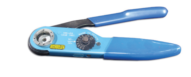
Contact Size AWG Hand-Crimp Tool Positioner (Locator) Plastic Insertion/ Metal Insertion Tool Metal Extraction Tool
K1461 2M809-057
20HD M22520/2-01 2M809-206 2M809-203 N/A N/A 20 M22520/1-01 M22520/1-04 M81969/14-10 11-008674-020 11-008675-020 16 M22520/1-01 M22520/1-04 M81969/14-03 11-008674-016 11-008675-016 12 M22520/1-01 M22520/1-04 M81969/14-04 11-008674-012 11-008675-012 * Metal & Insertion Only SOCKETSAMPHENOL 2M SERIES SOCKETS
Color Bands Wire Sealing Range Contact Size AWG Wire Size AWG Pin Contact 1 2 3 Wire Strip Length Min. Max. Wire Hole Filler
22,24,26, 26,28, 2M809-002 2M809-043 N/A Blue N/A N/A N/A N/A 0.15 N/A 0.024 N/A 0.052 N/A
20HD 20,22, 2M809-205 N/A N/A N/A 0.15 0.040 (1.02) 0.083 (2.11) MS27488-20-2 20 20,22, M39029/ Orange Green Violet .188 0.040 0.083 MS27488-20-2 16 16,18, M39029/ Orange Green Gray .188 0.065 0.109 MS27488-16-2 12 12 & 14 M39029/ Orange Green White .188 0.097 0.142 MS27488-12-2 All dimensions in inches (millimeters in parentheses).
Contact Size AWG Hand-Crimp Tool Positioner (Locator) Plastic Insertion/ Metal Insertion Tool Metal Extraction Tool
K1461 2M809-057
20HD M22520/2-01 2M809-206 2M809-203 N/A N/A 20 M22520/1-01 M22520/1-04 M81969/14-10 11-008674-020 11-008675-020 16 M22520/1-01 M22520/1-04 M81969/14-03 11-008674-016 11-008675-016 12 M22520/1-01 M22520/1-04 M81969/14-04 11-008674-012 11-008675-012 * Metal & Insertion Only |
|
2M 801 - CRIMPAMPHENOL 2M SERIES 2M 801 DUAL-START ACME THREADS CRIMP – PLUG
2M801-007-162M801-007-26 2M801-008-16 2M801-008-26
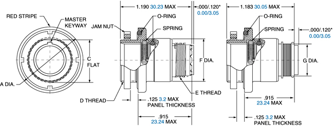
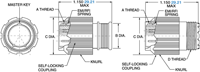
Shell Size Style 16 A Dia. Style 26 A Dia. B Thread C Dia. D Thread 5 0.545 (13.84) 0.660 (16.76) .3125-.05P-.1L-2B 0.245 (6.22) .250 - 32 UNEF-2A 6 0.610 (15.49) 0.710 (18.03) .3750-.05P-.1L-2B 0.290 (7.36) .3125 - 32 UNEF-2A 7 0.695 (17.65) 0.790 (20.07) .4375-.05P-.1L-2B 0.390 (9.91) .4375 - 28 UNEF-2A 8 0.750 (19.05) 0.860 (21.84) .5000-.05P-.1L-2B 0.445 (11.30) .5000 - 28 UNEF-2A 9 0.810 (20.57) 0.920 (23.37) .5625-.05P-.1L-2B 0.500 (12.70) .5625 - 24 UNEF-2A 10 0.890 (22.61) 0.985 (25.02) .6250-.05P-.1L-2B 0.560 (14.22) .6250 - 24 UNEF-2A 13 1.060 (26.92) 1.150 (29.21) .8125-.1P-.2L-2B 0.650 (16.51) .6875 - 24 UNEF-2A 16 1.250 (31.75) 1.345 (34.16) 1.0000-.1P-.2L-2B 0.805 (20.45) .9375 - 20 UNEF-2A 17 1.310 (33.27) 1.400 (35.56) 1.0625-.1P-.2L-2B 0.850 (21.59) .9375 - 20 UNEF-2A 21 1.560 (39.62) 1.660 (42.16) 1.3125-.1P-.2L-2B 1.135 (28.83) 1.1875 - 18 UNEF-2A All dimensions in inches (millimeters in parentheses) AMPHENOL 2M SERIES 2M 801 DUAL-START ACME THREADS JAM NUT CRIMP - RECEPTACLE
2M801-009-072M801-010-07
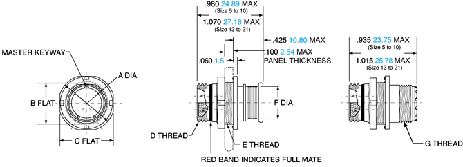
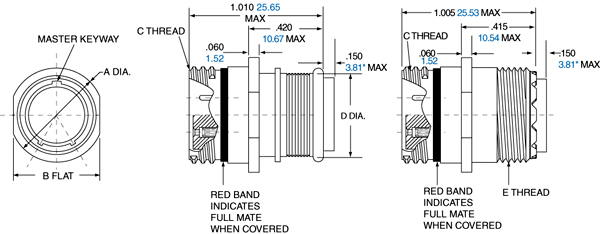
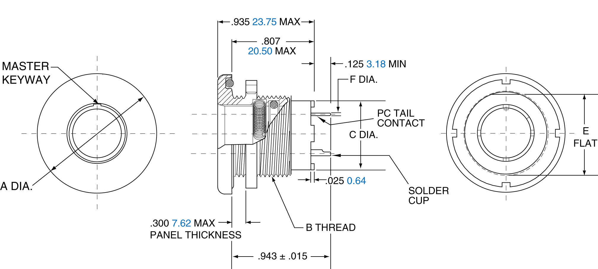
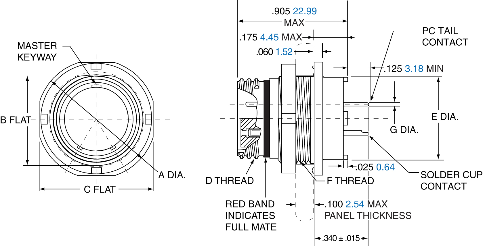
Shell Size A Dia. B Flat C Flat D Thread E Thread F Dia. G Thread 5 0.575 0.350 0.545 .3125-.05P-.1L-2A .3750-28 UN-2A 0.245 .2500-32 UNEF-2A 6 0.635 0.410 0.595 .3750-.05P-.1L-2A .4375-28 UNEF-2A 0.290 .3125-32 UNEF-2A 7 0.755 0.536 0.723 .4375-.05P-.1L-2A .5625-32 UN-2A 0.390 .4375-28 UNEF-2A 8 0.755 0.536 0.723 .5000-.05P-.1L-2A .5625-32 UN-2A 0.445 .5000-28 UNEF-2A 9 0.830 0.596 0.790 .5625-.05P-.1L-2A .6250-28 UN-2A 0.500 .5625-24 UNEF-2A 10 0.890 0.658 0.855 .6250-.05P-.1L-2A .6875-28 UN-2A 0.560 .6250-24 UNEF-2A 13 1.078 0.845 1.044 .8125-.1P-.2L-2A .8750-28 UN-2A 0.650 .6875-24 UNEF-2A 16 1.264 1.022 1.230 1.0000-.1P-.2L-2A 1.0625-20 UN-2A 0.805 .9375-20 UNEF-2A 17 1.325 1.096 1.290 1.0625-.1P-.2L-2A 1.125-28 UN-2A 0.850 .9375-20 UNEF-2A 21 1.625 1.345 1.577 1.3125-.1P-.2L-2A 1.375-28 UN-2A 1.110 1.1875-18 UNEF-2A All dimensions in inches (millimeters in parentheses)
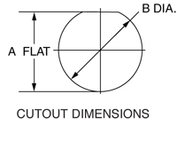
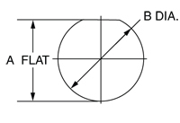
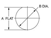
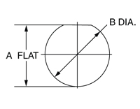
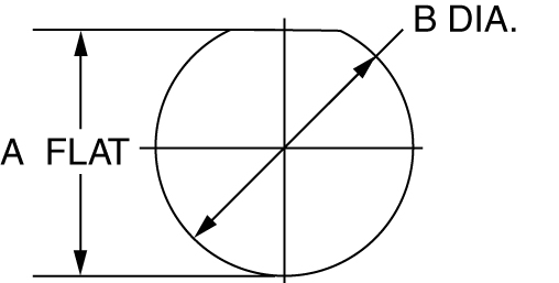
Jam Nut Panel Cutout Shell Size A Flat A Flat B Dia. B Dia. 5 0.356 9.04 0.385 9.78 6 0.416 10.57 0.447 11.35 7 0.542 13.77 0.572 14.53 8 0.542 13.77 0.572 14.53 9 0.602 15.29 0.635 16.13 10 0.666 16.62 0.697 17.7 13 0.851 21.62 0.885 22.48 16 1.028 26.11 1.075 27.31 17 1.102 27.99 1.135 28.83 21 1.354 34.39 1.385 35.18 AMPHENOL 2M SERIES 2M 801 DUAL-START ACME THREADS SQUARE FLANGED CRIMP - RECEPTACLE
2M801-009-022M801-010-02
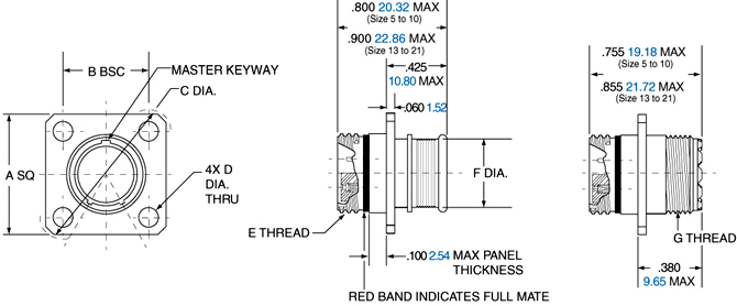
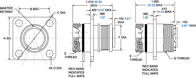
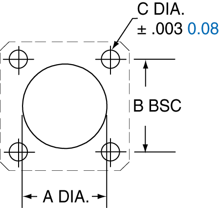
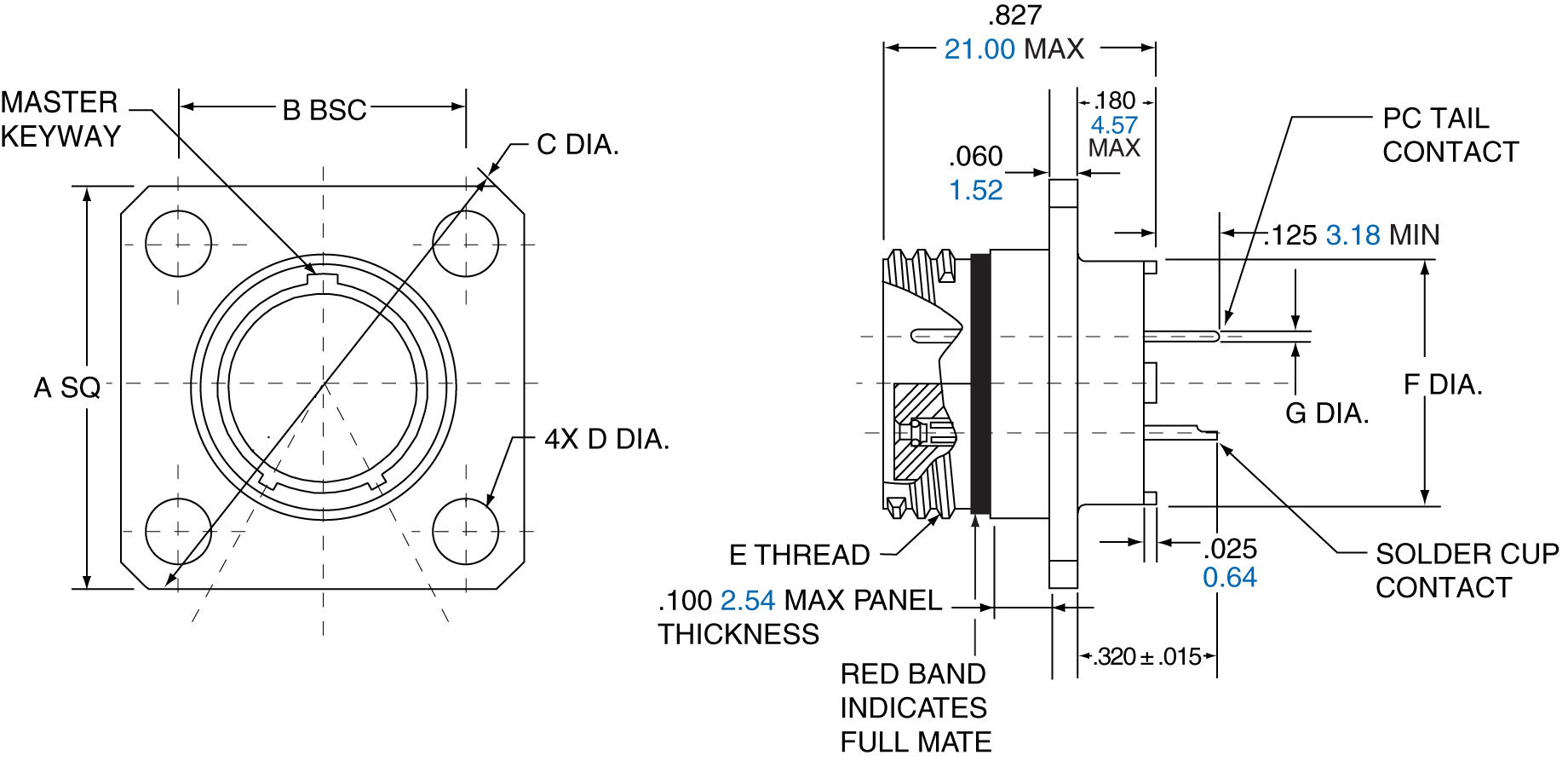
Shell Size A B BSC C Dia. D Dia. E Thread F Dia. G Thread 5 0.530 0.363 0.680 0.093 .3125-.05P-.1L-2A 0.245 .2500-32 UNEF-2A 6 0.590 0.423 0.750 0.093 .3750-.05P-.1L-2A 0.290 .3125-32 UNEF-2A 7 0.650 0.483 0.850 0.093 .4375-.05P-1L-2A 0.390 .4375-28 UNEF-2A 8 0.712 0.545 0.938 0.093 .5000-.05P-1L-2A 0.445 .5000-28 UNEF-2A 9 0.850 0.607 1.125 0.128 .5625-.05P-.1L-2A 0.500 .5625-24 UNEF-2A 10 0.890 0.670 1.188 0.128 .6250-.05P-1L-2A 0.560 .6250-24 UNEF-2A 13 1.030 0.812 1.375 0.128 .8125-.1P-.2L-2A 0.650 .6875-24 UNEF-2A 16 1.219 0.981 1.625 0.128 1.0000-.1P-.2L-2A 0.805 .9375-20 UNEF-2A 17 1.280 1.060 1.700 0.128 1.0625-.1P-.2L-2A 0.850 .9375-20 UNEF-2A 21 1.430 1.205 1.938 0.128 1.3125-.1P-.2L-2A 1.110 1.1875-18 UNEF-2A All dimensions in inches (millimeters in parentheses)
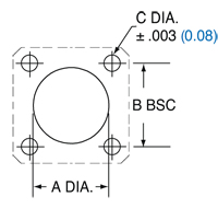
Flange Mount Panel Cutout Shell Size A Dia. A Dia. B Dia. B Dia. C Dia. C Dia. 5 0.330 8.38 0.363 9.22 0.093 2.36 6 0.390 9.91 0.423 10.74 0.093 2.36 7 0.450 11.43 0.483 12.27 0.093 2.36 8 0.510 12.95 0.545 13.84 0.093 2.36 9 0.575 14.61 0.607 15.42 0.128 3.25 10 0.640 16.26 0.670 17.02 0.128 3.25 13 0.825 20.96 0.812 20.65 0.128 3.25 16 1.015 25.78 0.981 24.92 0.128 3.25 17 1.075 27.31 1.060 26.92 0.128 3.25 21 1.325 33.66 1.205 30.61 0.128 3.25 AMPHENOL 2M SERIES 2M 801 DUAL-START ACME THREADS IN-LINE CRIMP – RECEPTACLE
2M801-009-012M801-010-01
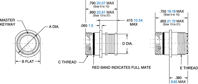
Shell Size A Dia. B Flat C Thread D Dia. E Thread 5 0.355 (9.02) 0.325 (8.13) .3125-.05P-.1L-2A 0.245 (6.22) .2500-32 UNEF-2A 6 0.415 (10.54) 0.385 (9.78) .3750-.05P-.1L-2A 0.290 (7.37) .3125-32 UNEF-2A 7 0.480 (12.19) 0.445 (11.30) .4375-.05P-.1L-2A 0.390 (9.91) .4375-28 UNEF-2A 8 0.540 (13.72) 0.510 (12.95) .5000-.05P-.1L-2A 0.445 (11.30) .5000-28 UNEF-2A 9 0.605 (15.37) 0.575 (14.61) .5625-.05P-.1L-2A 0.500 (12.70) .5625-24 UNEF-2A 10 0.665 (16.89) 0.635 (16.13) .6250-.05P-.1L-2A 0.560 (14.22) .6250-24 UNEF-2A 13 0.855 (21.72) 0.825 (20.96) .8125-.1P-.2L-2A 0.650 (16.51) .6875-24 UNEF-2A 16 1.040 (26.42) 1.010 (25.65) 1.0000-.1P-.2L-2A 0.805 (20.44) .9375-20 UNEF-2A 17 1.110 (28.19) 1.070 (27.18) 1.0625-.1P-.2L-2A 0.850 (21.59) .9375-20 UNEF-2A 21 1.405 (35.69) 1.385 (35.18) 1.3125-.1P-2L-2A 1.110 (28.19) 1.1875-18 UNEF-2A All dimensions in inches (millimeters in parentheses) 2M 803 - CRIMPAMPHENOL 2M SERIES 2M 803 1/4 TURN BAYONET COUPLING CRIMP – PLUG
2M803-001-062M803-002-06
Shell Size A Thread B Dia. Max B Dia. Max C Dia. C Dia. 5 .2500-32 UNEF-2A 0.475 12.07 0.245 6.22 6 .3125-32 UNEF-2A 0.540 13.72 0.290 7.37 7 .4375-28 UNEF-2A 0.620 15.75 0.390 9.91 8 .5000-28 UNEF-2A 0.675 17.15 0.450 11.43 9 .5625-24 UNEF-2A 0.745 18.92 0.500 12.70 10 .6250-24 UNEF-2A 0.812 20.63 0.562 14.28 12 .6875-24 UNEF-2A 0.894 22.71 0.650 16.51 14 .9375-20 UNEF-2A 1.060 26.92 0.800 20.32 15 .9375-20 UNEF-2A 1.120 28.45 1.035 26.29 AMPHENOL 2M SERIES 2M 803 1/4 TURN BAYONET COUPLING IN-LINE CRIMP – RECEPTACLE
2M803-003-012M803-004-01
Shell Size A Max. B Dia. C Thread D Dia. 5 0.385 (9.78) 0.300 (7.62) .2500-32 UNEF-2A 0.245 (6.22) 6 0.465 (11.81) 0.362 (9.19) .3125-32 UNEF-2A 0.290 (7.37) 7 0.485 (12.32) 0.438 (11.13) .4375-28 UNEF-2A 0.390 (9.91) 8 0.566 (14.38) 0.498 (12.65) .5000-28 UNEF-2A 0.450 (11.43) 9 0.658 (16.71) 0.564 (14.33) .5625-24 UNEF-2A 0.500 (12.70) 10 0.720 (18.29) 0.636 (16.15) .6250-24 UNEF-2A 0.562 (14.27) 12 0.810 (20.57) 0.713 (18.11) .6875-24 UNEF-2A 0.650 (16.51) 14 1.027 (26.09) 0.865 (21.97) .9375-20 UNEF-2A 0.805 (20.44) 15 1.027 (26.09) 0.924 (23.47) .9375-20 UNEF-2A 0.850 (21.59) All dimensions in inches (millimeters in parentheses) AMPHENOL 2M SERIES 2M 803 1/4 TURN BAYONET COUPLING PANEL MOUNT CRIMP - RECEPTACLE
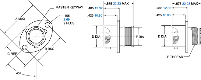
2M803-003-022M803-004-02
Shell Size A Max. B BSC C Ref. D Dia. E Thread F Dia. 5 0.710 (18.03) 0.513 (13.03) 0.460 (11.68) 0.300 (7.62) .2500-32 UNEF-2A 0.245 (6.30) 6 0.788 (20.02) 0.598 (15.19) 0.522 (13.26) 0.362 (9.19) .3125-32 UNEF-2A 0.290 (7.44) 7 0.895 (22.73) 0.708 (17.98) 0.590 (14.99) 0.436 (11.07) .4375-28 UNEF-2A 0.390 (9.86) 8 1.154 (29.31) 0.964 (24.49) 0.668 (16.97) 0.500 (12.70) .5000-28 UNEF-2A 0.450 (11.38) 9 1.200 (30.72) 1.017 (25.83) 0.721 (18.31) 0.561 (14.25) .5625-24 UNEF-2A 0.500 (12.78) 10 1.291 (32.79) 1.101 (27.97) 0.795 (20.19) 0.635 (16.13) .6250-24 UNEF-2A 0.562 (14.30) 12 1.395 (35.43) 1.204 (30.58) 0.874 (22.20) 0.714 (18.14) .6875-24 UNEF-2A 0.650 (16.71) 14 1.550 (39.37) 1.280 (32.51) 1.050 (26.67) 0.865 (21.97) .9375-20 UNEF-2A 0.805 (20.40) All dimensions in inches (millimeters in parentheses)
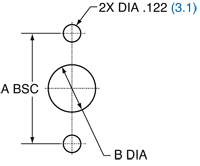
Flange Mount Panel Cutout Shell Size A BSC. A BSC. B Dia. B Dia. 5 0.513 13.03 0.365 9.25 6 0.598 15.19 0.430 10.92 7 0.708 17.98 0.520 13.21 8 0.964 17.98 0.592 15.04 9 1.017 25.83 0.645 16.38 10 1.101 27.97 0.726 18.44 12 1.204 30.58 0.832 21.13 14 1.280 32.51 0.945 24.00 AMPHENOL 2M SERIES 2M 803 1/4 TURN BAYONET COUPLING PANEL JAM NUT CRIMP – RECEPTACLE
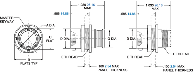
2M803-003-072M803-004-07
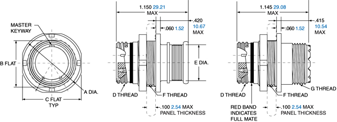
Shell Size A Dia. B Flat C Flat. D Dia. E Thread F Thread G Dia. 5 0.575 (14.61) 0.545 (13.84) 0.350 (8.89) 0.300 (7.62) .3750-32 UNEF-2A .2500-32 UNEF-2A 0.245 (6.30) 6 0.635 (16.13) 0.595 (15.11) 0.410 (10.41) 0.362 (9.19) .4375-28 UNEF-2A .3125-32 UNEF-2A 0.290 (7.37) 7 0.755 (19.18) 0.723 (18.36) 0.536 (13.61) 0.436 (11.07) .5625-32 UN-2A .4375-28 UNEF-2A 0.390 (9.91) 8 0.830 (21.08) 0.790 (20.11) 0.593 (15.10) 0.498 (12.65) .6250-28 UN-2A .5000-28 UNEF-2A 0.450 (11.43) 9 0.830 (21.08) 0.790 (20.07) 0.596 (15.14) 0.561 (14.25) .6250-28 UN-2A .5625-24 UNEF-2A 0.500 (12.70) 10 0.955 (24.26) 0.925 (23.51) 0.721 (18.31) 0.635 (16.13) .7500-28 UN-2A .6250-24 UNEF-2A 0.562 (14.27) 12 1.078 (27.38) 1.044 (26.52) 0.845 (21.46) 0.714 (18.14) .8750-28 UN-2A .6875-24 UNEF-2A 0.650 (16.51) 14 1.264 (32.11) 1.230 (31.24) 1.022 (25.96) 0.865 (21.97) 1.0625-20 UN-2A .9375-20 UNEF-2A 0.805 (20.45) 15 1.322 (33.58) 1.287 (32.69) 1.093 (27.76) 0.924 (23.47) 1.1250-28 UN-2A .9375-20 UNEF-2A 0.850 (21.59) All dimensions in inches (millimeters in parentheses)
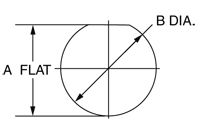
Jam Nut Panel Cutout Shell Size A Flat A Flat B Dia. B Dia. 5 0.355 9.02 0.382 9.70 6 0.415 10.54 0.445 11.30 7 0.541 13.74 0.572 14.53 8 0.601 15.27 0.635 16.13 9 0.601 15.27 0.643 16.33 10 0.729 18.52 0.760 18.29 12 0.850 21.59 0.885 22.48 14 1.031 23.19 1.072 27.23 All dimensions in inches (millimeters in parentheses) 2M 804 - CRIMPAMPHENOL 2M SERIES 2M 804 PUSH-PULL CRIMP – PLUG
2M804-001-062M804-002-06
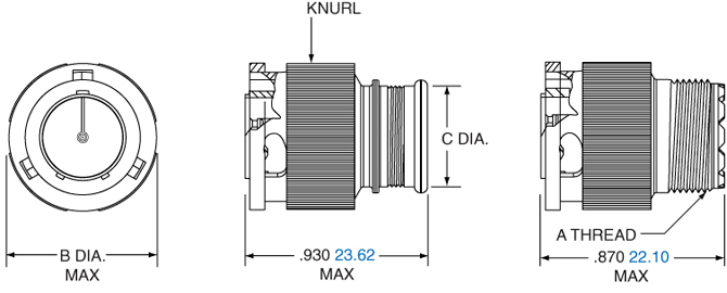
Shell Size A Dia. B Dia. C Dia. D Dia. E Thread 5 0.418 (10.62) 0.245 (6.22) 0.218 (5.54) 0.248 (6.30) .2500-32 UNEF-2A 6 0.488 (12.40) 0.310 (7.87) 0.275 (6.99) 0.293 (7.44) .3125-32 UNEF-2A 7 0.561 (14.25) 0.378 (9.60) 0.350 (8.89) 0.388 (9.86) .4375-28 UNEF-2A 8 0.603 (15.32) 0.426 (10.82) 0.395 (10.03) 0.448 (11.38) .5000-28 UNEF-2A 9 0.663 (16.84) 0.482 (12.24) 0.450 (11.43) 0.503 (12.78) .5625-24 UNEF-2A 10 0.743 (18.87) 0.555 (14.10) 0.525 (13.34) 0.563 (14.30) .6250-24 UNEF-2A 12 0.851 (21.62) 0.672 (17.07) 0.642 (16.31) 0.653 (16.59) .6875-24 UNEF-2A 14 0.978 (24.84) 0.795 (20.19) 0.761 (19.33) 0.803 (20.40) .9375-20 UNEF-2A 15 1.038 (26.37) 0.863 (21.92) 0.837 (21.26) 0.853 (21.67) .9375-20 UNEF-2A All dimensions in inches (millimeters in parentheses) AMPHENOL 2M SERIES 2M 804 PUSH-PULL IN-LINE CRIMP – RECEPTACLE
2M804-004-012M804-003-01
Shell Size A Dia. B Thread C Dia. 5 0.453 (11.51) .2500-32 UNEF-2A 0.248 (6.30) 6 0.523 (13.28) .3125-32 UNEF-2A 0.293 (7.44) 7 0.583 (14.81) .4375-28 UNEF-2A 0.388 (9.86) 8 0.606 (15.39) .5000-28 UNEF-2A 0.448 (11.38) 9 0.698 (17.73) .5625-24 UNEF-2A 0.503 (12.78) 10 0.738 (18.75) .6250-24 UNEF-2A 0.563 (14.30) 12 0.883 (22.43) .6875-24 UNEF-2A 0.653 (16.59) 14 1.013 (25.73) .9375-20 UNEF-2A 0.803 (20.40) 15 1.061 (26.95) .9375-20 UNEF-2A 0.853 (21.67) All dimensions in inches (millimeters in parentheses) AMPHENOL 2M SERIES 2M 804 PUSH-PULL REAR MOUNT JAM NUT CRIMP – RECEPTACLE
2M804-004-072M804-003-07
Shell Size A Dia. C Flat D Thread E Thread F Dia. G Dia. 5 0.773 0.414 .4375-32 UNEF-2A .2500-32 UNEF-2A 0.448 0.248 6 0.833 0.468 .5000-32 UNEF-2A .3125-32 UNEF-2A 0.513 0.293 7 0.903 0.593 .6250-28 UNEF-2A .4375-28 UNEF-2A 0.573 0.388 8 0.958 0.593 .6250-28 UNEF-2A .5000-28 UNEF-2A 0.596 0.448 9 0.998 0.653 .6875-28 UNEF-2A .5625-24 UNEF-2A 0.691 0.503 10 1.083 0.721 .7500-28 UNEF-2A .6250-24 UNEF-2A 0.728 0.563 12 1.183 0.843 .8750-28 UNEF-2A .6875-24 UNEF-2A 0.883 0.653 14 1.323 0.968 1.0000-28 UNEF-2A .9375-20 UNEF-2A 1.003 0.803 15 1.373 1.036 1.0625-20 UNEF-2A .9375-20 UNEF-2A 1.063 0.853 All dimensions in inches (millimeters in parentheses)
Rear Mount Jam Nut Panel Cutout Shell Size A Flat A Flat B Dia. B Dia. 5 0.423 10.74 0.448 11.38 6 0.475 12.07 0.510 12.95 7 0.602 15.29 0.635 16.13 8 0.602 15.29 0.635 16.13 9 0.663 16.84 0.698 17.73 10 0.729 18.82 0.760 19.30 12 0.851 21.62 0.885 22.48 14 0.976 24.79 1.010 25.65 15 1.043 26.49 1.073 27.25 AMPHENOL 2M SERIES 2M 804 PUSH-PULL FRONT MOUNT JAM NUT CRIMP – RECEPTACLE
2M804-004-002M804-003-00
Shell Size A Dia. B Thread C Thread D Dia. F Flat 5 0.830 (21.08) .5000-32 UN-2A .2500-32 UNEF-2A 0.248 (6.30) 0.470 (11.94) 6 0.884 (22.45) .5625-32 UN-2A .3125-32 UNEF-2A 0.293 (7.44) 0.529 (13.44) 7 0.994 (25.27) .6875-28 UN-2A .4375-28 UNEF-2A 0.388 (9.86) 0.663 (16.84) 8 0.994 (25.27) .6875-28 UN-2A .5000-28 UNEF-2A 0.448 (11.38) 0.663 (16.84) 9 1.073 (27.31) .7500-28 UN-2A .5625-24 UNEF-2A 0.503 (12.78) 0.719 (18.26) 10 1.138 (28.95) .8125-28 UN-2A .6250-24 UNEF-2A 0.563 (14.30) 0.778 (19.76) 12 1.338 (34.04) 1.0000-28 UN-2A .6875-24 UNEF-2A 0.653 (16.59) 0.969 (24.61) 14 1.388 (35.31) 1.0625-20 UN-2A .9375-20 UNEF-2A 0.803 (20.40) 1.019 (25.88) 15 1.453 (36.91) 1.1250-28 UN-2A .9375-20 UNEF-2A 0.853 (21.67) 1.113 (28.27) All dimensions in inches (millimeters in parentheses)
Front Mount Jam Nut Panel Cutout Shell Size A Flat A Flat B Dia. B Dia. 5 0.477 12.12 0.510 12.95 6 0.537 13.64 0.573 14.55 7 0.670 17.02 0.698 17.73 8 0.670 17.02 0.698 17.73 9 0.727 18.47 0.760 19.30 10 0.787 20.19 0.823 20.90 12 0.977 24.82 1.010 25.65 14 1.027 26.09 1.073 27.25 15 1.121 28.47 1.135 28.83 All dimensions in inches (millimeters in parentheses) 2M 805 - CRIMPAMPHENOL 2M SERIES 2M 805 TRI-START CRIMP – PLUG
2M805-0012M805-002
Shell Size A Threads B Dia. C Dia. D Threads Accessory 8 .5000-.1P-.3L-TS-2B 0.317 (8.05) 0.691 (17.55) .3750-32 UNEF-2A 9 .5625-.1P-.3L-TS-2B 0.397 (10.08) 0.787 (19.99) .4375-28 UNEF-2A 10 .6250-.1P-.3L-TS-2B 0.473 (12.01) 0.826 (20.98) .5000-28 UNEF-2A 11 .6875-.1P-.3L-TS-2B 0.519 (13.18) 0.925 (23.50) .5625-24 UNEF-2A 12 .7500-.1P-.3L-TS-2B 0.585 (14.86) 0.982 (24.94) .6250-24 UNEF-2A 15 .9375-.1P-.3L-TS-2B 0.687 (17.45) 1.105 (28.07) .7500-20 UNEF-2A 18 1.1250-.1P-.3L-TS-2B 0.884 (22.45) 1.275 (32.29) .9375-20 UNEF-2A 19 1.1875-.1P-.3L-TS-2B 0.884 (22.45) 1.310 (33.27) .9375-20 UNEF-2A 23 1.4375-.1P-.3L-TS-2B 1.135 (28.83) 1.562 (39.67) 1.1875-18 UNEF-2A All dimensions in inches (millimeters in parentheses) AMPHENOL 2M SERIES 2M 805 TRI-START IN-LINE CRIMP – RECEPTACLE
2M805-003-012M805-004-01
Shell Size A Dia. B Flat C Threads D Dia. E Threads Accessory 8 0.543 (13.79) 0.513 (13.03) .5000-.1P-.3L-TS-2A 0.317 (8.05) .3750-32 UNEF-2A 9 0.608 (15.44) 0.578 (14.68) .5625-.1P-.3L-TS-2A 0.397 (10.08) .4375-28 UNEF-2A 10 0.671 (17.04) 0.641 (16.28) .6250-.1P-.3L-TS-2A 0.473 (12.01) .5000-28 UNEF-2A 11 0.733 (18.62) 0.703 (17.86) .6875-.1P-.3L-TS-2A 0.519 (13.18) .5625-24 UNEF-2A 12 0.796 (20.22) 0.766 (19.46) .7500-.1P-.3L-TS-2A 0.585 (14.86) .6250-24 UNEF-2A 15 0.983 (24.97) 0.953 (24.21) .9375-.1P-.3L-TS-2A 0.687 (17.45) .7500-20 UNEF-2A 18 1.168 (29.67) 1.138 (28.91) 1.1250-.1P-.3L-TS-2A 0.884 (22.45) .9375-20 UNEF-2A 19 1.238 (31.45) 1.208 (30.68) 1.1875-.1P-.3L-TS-2A 0.884 (22.45) .9375-20 UNEF-2A 23 1.485 (37.72) 1.455 (39.96) 1.4375-.1P-.3L-TS-2A 1.135 (28.83) 1.1875-18 UNEF-2A All dimensions in inches (millimeters in parentheses) AMPHENOL 2M SERIES 2M 805 TRI-START SQUARE FLANGED CRIMP – RECEPTACLE
2M805-003-022M805-004-02
Shell Size A Sq. B BSC C Dia. D Dia. E Threads F Dia. G Threads Accessory 8 0.853 (21.67) 0.660 (16.76) 1.153 (29.29) 0.091 (2.31) .5000-.1P-.3L-TS-2A 0.317 (8.05) .3750-32 UNEF-2A 9 0.916 (23.27) 0.723 (18.36) 1.233 (31.32) 0.091 (2.31) .5625-.1P-.3L-TS-2A 0.397 (10.08) .4375-28 UNEF-2A 10 0.978 (24.84) 0.785 (19.94) 1.333 (33.86) 0.091 (2.31) .6250-.1P-.3L-TS-2A 0.473 (12.01) .5000-28 UNEF-2A 11 1.042 (26.47) 0.848 (21.54) 1.413 (35.89) 0.091 (2.31) .6875-.1P-.3L-TS-2A 0.519 (13.18) .5625-24 UNEF-2A 12 1.102 (27.99) 0.909 (23.09) 1.503 (38.18) 0.091 (2.31) .7500-.1P-.3L-TS-2A 0.585 (14.86) .6250-24 UNEF-2A 15 1.291 (32.79) 1.058 (26.87) 1.753 (44.53) 0.125 (3.18) .9375-.1P-.3L-TS-2A 0.687 (17.45) .7500-20 UNEF-2A 18 1.478 (37.54) 1.255 (31.88) 2.003 (50.88) 0.125 (3.18) 1.1250-.1P-.3L-TS-2A 0.884 (22.45) .9375-20 UNEF-2A 19 1.540 (39.12) 1.327 (33.71) 2.097 (53.26) 0.125 (3.18) 1.1875-.1P-.3L-TS-2A 0.884 (22.45) .9375-20 UNEF-2A 23 1.790 (45.47) 1.570 (39.88) 2.443 (62.05) 0.125 (3.18) 1.4375-.1P-.3L-TS-2A 1.135 (28.83) 1.1875-18 UNEF-2A All dimensions in inches (millimeters in parentheses) AMPHENOL 2M SERIES 2M 805 TRI-START JAM NUT CRIMP – RECEPTACLE
2M805-003-072M805-004-07
Shell Size A Dia. B Flat C Flat D Threads E Dia. F Threads G Threads Accessory 8 0.760 (19.30) 0.535 (13.59) 0.730 (18.54) .5000-.1P-.3L-TS-2A 0.317 (8.05) .5625-28 UNEF-2A .3750-32 UNEF-2A 9 0.880 (22.35) 0.661 (16.79) 0.850 (21.59) .5625-.1P-.3L-TS-2A 0.397 (10.08) .6875-28 UN-2A .4375-28 UNEF-2A 10 0.880 (22.35) 0.661 (16.79) 0.850 (21.59) .6250-.1P-.3L-TS-2A 0.473 (12.01) .6875-28 UN-2A .5000-28 UNEF-2A 11 0.955 (24.26) 0.721 (18.31) 0.925 (23.50) .6875-.1P-.3L-TS-2A 0.519 (13.18) .7500-28 UN-2A .5625-24 UNEF-2A 12 1.065 (27.05) 0.784 (19.91) 1.039 (26.39) .7500-.1P-.3L-TS-2A 0.585 (14.86) .8125-28 UN-2A .6250-24 UNEF-2A 15 1.203 (30.56) 0.970 (24.64) 1.173 (29.79) .9375-.1P-.3L-TS-2A 0.687 (17.45) 1.0000-28 UN-2A .7500-20 UNEF-2A 18 1.395 (35.43) 1.150 (29.21) 1.359 (34.52) 1.1250-.1P-.3L-TS-2A 0.884 (22.45) 1.1875-28 UN-2A .9375-20 UNEF-2A 19 1.450 (36.83) 1.221 (31.01) 1.420 (36.07) 1.1875-.1P-.3L-TS-2A 0.884 (22.45) 1.2500-28 UN-2A .9375-20 UNEF-2A 23 1.705 (43.31) 1.470 (37.34) 1.678 (42.62) 1.4375-.1P-.3L-TS-2A 1.135 (28.83) 1.5000-28 UN-2A 1.1875-18 UNEF-2A All dimensions in inches (millimeters in parentheses)
Jam Nut Panel Cutout Shell Size A Flat A Flat B Dia. B Dia. 8 0.543 13.79 0.572 14.53 9 0.669 16.99 0.698 17.73 10 0.669 16.99 0.698 17.73 11 0.729 18.51 0.760 19.30 12 0.792 20.17 0.822 20.88 15 0.978 24.84 1.010 25.65 18 1.155 29.34 1.198 30.43 19 1.231 31.27 1.260 32.00 23 1.480 37.59 1.510 38.35 All dimensions in inches (millimeters in parentheses) 2M 801 - PCBAMPHENOL 2M SERIES 2M 801 DUAL-START ACME THREADS PC TAIL/SOLDER CUP -
JAM NUT AND SQUARE FLANGE 2M801-011 AND 2M801-033
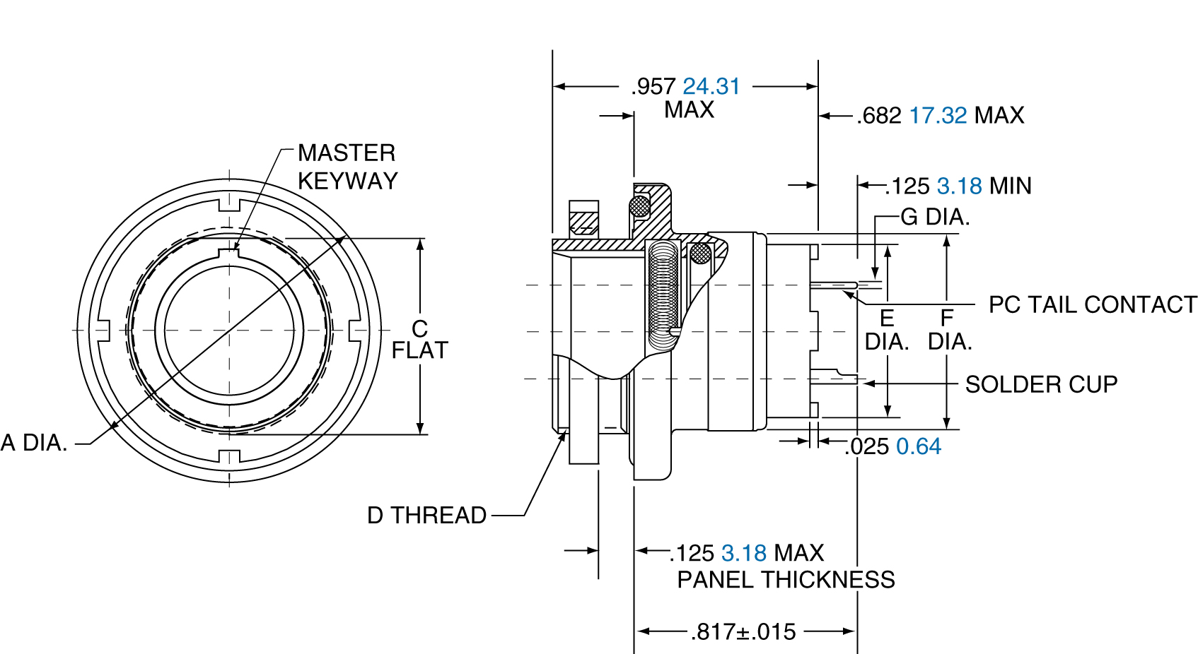
Shell Size A Dia. B Flat C Flat D Thread E Thread F Dia. G Sq. H BSC J Dia. K Dia. L Dia. 5 6 7 8 9 10 13 16 17 21 0.575 (14.61) 0.635 (16.13) 0.755 (19.18) 0.755 (19.18) 0.830 (21.08) 0.890 (22.61) 1.078 (27.38) 1.264 (32.11) 1.325 (33.66) 1.625 (41.28) 0.350 (8.69) 0.410 (10.41) 0.536 (13.61) 0.536 (13.61) 0.596 (15.14) 0.658 (16.71) 0.845 (21.46) 1.022 (25.98) 1.096 (27.84) 1.345 (34.16) 0.545 (13.84) 0.595 (15.11) 0.723 (18.36) 0.595 (15.11) 0.790 (20.07) 0.855 (21.72) 1.044 (26.52) 1.230 (31.24) 1.290 (32.77) 1.577 (40.06) .3125-.05P-.1L-2A .3750-.05P- .4375-.05P- .5000-.05P- .5625-.05P- .6250-.05P- .8125-.1P- 1.0000-.1P- 1.0625-.1P- 1.3125-.1P- .3750-28 .4375-28 .5625-32 .5625-32 .6250-28 .6875-28 .8750-28 1.0625-20 1.1250-28 1.3750-28 0.244 (6.20) 0.330 (8.38) 0.432 (10.97) 0.493 (12.52) 0.551 (14.00) 0.620 (15.75) 0.703 (17.86) 0.863 (21.92) 0.912 (23.16) 1.170 (29.72) 0.530 (13.46) 0.590 (14.99) 0.650 (16.51) 0.712 (18.08) 0.850 (21.56) 0.890 (22.61) 1.030 (26.16) 1.219 (30.96) 1.280 (32.51) 1.430 (36.32) 0.363 (9.22) 0.423 (10.74) 0.483 (12.27) 0.545 (13.84) 0.607 (15.42) 0.670 (17.02) 0.812 (20.62) 0.981 (24.92) 1.060 (26.92) 1.322 (33.58) 0.680 (17.27) 0.750 (19.05) 0.850 (21.59) 0.940 (23.88) 1.125 (28.58) 1.190 (30.23) 1.375 (34.93) 1.625 (41.28) 1.700 (43.18) 1.940 (49.28) 0.093 (2.36) 0.093 (2.36) 0.093 (2.36) 0.093 (2.36) 0.128 (3.25) 0.128 (3.25) 0.128 (3.25) 0.128 (3.25) 0.128 (3.25) 0.128 (3.25) #23
Square Flange 02 Jam Nut 07
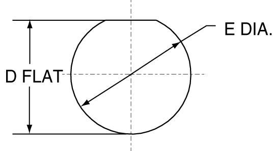
Panel Cutout Shell Size A Dia. B Dia. C Dia. D Flat ±.002 (0.05) E Dia. ±.002 (0.05) 5 0.330 (8.38) 0.363 (9.22) 0.093 (2.36) 0.356 (9.04) 0.385 (9.78) 6 0.390 (9.91) 0.423 (10.74) 0.093 (2.36) 0.416 (10.57) 0.447 (11.35) 7 0.450 (11.43) 0.483 (12.27) 0.093 (2.36) 0.542 (13.77) 0.572 (14.53) 8 0.510 (12.95) 0.545 (13.84) 0.093 (2.36) 0.542 (13.77) 0.572 (14.53) 9 0.575 (14.61) 0.607 (15.42) 0.128 (3.25) 0.602 (15.29) 0.635 (16.13) 10 0.640 (16.26) 0.670 (17.02) 0.128 (3.25) 0.666 (16.92) 0.697 (17.70) 13 0.825 (20.96) 0.812 (20.65) 0.128 (3.25) 0.851 (21.62) 0.885 (22.48) 16 1.015 (25.78) 0.981 (24.92) 0.128 (3.25) 1.028 (26.11) 1.075 (27.31) 17 1.075 (27.31) 1.060 (26.92) 0.128 (3.25) 1.102 (27.99) 1.135 (28.83) 21 1.330 (33.78) 1.322 (33.58) 0.128 (3.25) 1.354 (34.39) 1.385 (35.18) All dimensions in inches (millimeters in parentheses) AMPHENOL 2M SERIES 2M 801 DUAL-START ACME THREADS PC TAIL/SOLDER CUP - JAM NUT CONNECTOR 2M801-023-07
Shell Size A ±.005 (0.13) B C Dia. D Thread E Thread F G ±.035 (0.89) H J K 5-3 0.350 (8.89) 0.548 (13.92) 0.575 (14.61) .3125-.05P-.1L-2A .3750-28 UN-2A 0.225 (5.72) 0.275 (6.99) 0.260 (6.60) 0.165 (4.19) 0.310 (7.87) 6-4 0.410 (10.41) 0.598 (15.19) 0.635 (16.13) .3750-.05P-.1L-2A .4375-28 UNEF-2A 0.225 (5.72) 0.265 (6.73) 0.345 (8.76) 0.187 (4.75) 0.408 (10.36) 6-7 0.410 (10.41) 0.598 (15.19) 0.635 (16.13) .3750-.05P-.1L-2A .4375-28 UNEF-2A 0.225 (5.72) 0.265 (6.73) 0.345 (8.76) 0.187 (4.75) 0.408 (10.36) 7-10 0.536 (13.61) 0.726 (18.44) 0.755 (19.18) .4375-.05P-.1L-2A .5625-32 UN-2A 0.296 (7.52) 0.273 (6.93) 0.345 (8.76) 0.170 (4.32) 0.452 (11.48) 8-2 0.538 (13.67) 0.728 (18.49) 0.758 (19.25) .5000-.05P-.1L-2A .5625-32 UN-2A 0.319 (8.10) 0.316 (8.03) 0.490 (12.45) 0.230 (5.84) 0.490 (12.45) 8-13 0.538 (13.67) 0.728 (18.49) 0.758 (19.25) .5000-.05P-.1L-2A .5625-32 UN-2A 0.319 (8.10) 0.316 (8.03) 0.490 (12.45) 0.230 (5.84) 0.490 (12.45) 9-19 0.596 (15.14) 0.793 (20.14) 0.833 (21.16) .5625-.05P-.1L-2A .6250-28 UN-2A 0.360 (9.14) 0.275 (6.99) 0.490 (12.45) 0.342 (8.69) 0.600 (15.24)
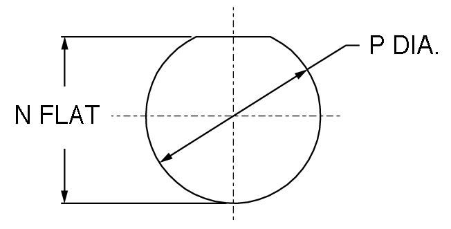
Panel Cutout Shell Size L N ±.002 (0.05) P ±.005 (0.13) 5-3 0.490 (14.45) 0.357 (9.07) 0.385 (9.78) 6-4 0.589 (15.19) 0.418 (10.62) 0.448 (11.37) 6-7 0.589 (15.19) 0.418 (10.62) 0.448 (11.37) 7-10 0.710 (18.03) 0.544 (13.82) 0.573 (14.55) 8-2 0.710 (18.03) 0.544 (13.82) 0.573 (14.55) 8-13 0.710 (18.03) 0.544 (13.82) 0.573 (14.55) 9-19 0.800 (20.32) 0.603 (15.32) 0.635 (16.13) All dimensions in inches (millimeters in parentheses) 2M 803 - PCBAMPHENOL 2M SERIES 2M 803 1/4 TURN BAYONET COUPLING PC TAIL/SOLDER CUP - FLANGE MOUNT & JAM NUT RECEPTACLE 2M803-005-02 & 07
Shell Size A Max. B BSC. C Ref. D Dia. E Flats F Flats G Dia. H Thread J Dia. 5 6 7 8 9 10 12 14 15 0.710 (18.03) 0.788 (20.02) 0.895 (22.73) 1.154 (29.31) 1.210 (30.73) 1.291 (32.79) 1.395 (35.43) 1.550 (39.37) N/A 0.513 (13.03) 0.598 (15.19) 0.708 (17.98) 0.964 (24.49) 1.017 (25.83) 1.101 (27.97) 1.204 (30.58) 1.280 (32.51) N/A 0.460 (11.68) 0.522 (13.26) 0.590 (14.99) 0.665 (16.97) 0.721 (18.31) 0.795 (20.19) 0.874 (22.20) 1.050 (26.67) N/A 0.300 (7.62) 0.362 (9.19) 0.436 (11.07) 0.498 (12.70) 0.561 (14.25) 0.635 (16.13) 0.714 (18.14) 0.865 (21.97) 0.924 (23.47) 0.545 (13.84) 0.595 (15.11) 0.723 (18.36) 0.790 (20.07) 0.790 (20.07) 0.925 (23.51) 1.044 (26.52) 1.230 (31.24) 1.287 (32.69) 0.350 (8.89) 0.410 (10.42) 0.536 (13.61) 0.593 (15.10) 0.596 (15.14) 0.721 (23.49) 0.845 (21.46) 1.022 (25.96) 1.093 (27.76) 0.575 (14.61) 0.635 (16.13) 0.755 (19.18) 0.830 (21.08) 0.830 (21.08) 0.955 (24.26) 1.078 (27.38) 1.264 (32.11) 1.322 (33.58) .3750-32 UNEF-2A .4375-28 UNEF-2A .5625-32 UN-2A .6250-28 UN-2A .6250-28 UN-2A .8500-28 UN-2A .8750-28 UN-2A 1.0625-20 UN-2A 1.1250-28 UN-2A
#20/20HD #16 #12 All dimensions in inches (millimeters in parentheses) 2M 804 - PCBAMPHENOL 2M SERIES 2M 804 PUSH-PULL PC TAIL/SOLDER CUP - REAR PANEL JAM NUT RECEPTACLE - 2M804-005-07, 2M804-020-07
Shell Size A Dia. C Flat D Thread UN-2A E Dia. F Dia. G PC Tail Dia. 5 6 7 8 9 10 12 14 15 0.773 0.833 0.903 0.958 0.998 1.083 1.183 1.323 1.373 0.414 0.468 0.593 0.593 0.653 0.721 0.843 0.968 1.036 .4375-32 .5000-32 .6250-28 .6250-28 .6875-28 .7500-28 .8750-28 1.0000-28 1.0625-20 0.274 0.329 0.431 0.493 0.551 0.619 0.703 0.863 0.913 0.448 0.513 0.573 0.596 0.691 0.728 0.883 1.003 1.063 #23 #20/20HD #16 #12
Jam Nut Panel Cutout Shell Size A Flat ±.002 (0.05) B Dia. ±.005 (0.13) 5 0.423 (10.74) 0.448 (11.38) 6 0.475 (12.07) 0.510 (12.95) 7 0.602 (15.29) 0.635 (16.13) 8 0.602 (15.29) 0.635 (16.13) 9 0.663 (16.84) 0.698 (17.73) 10 0.729 (18.82) 0.760 (19.30) 12 0.851 (21.62) 0.885 (22.48) 14 0.976 (24.79) 1.010 (25.65) 15 1.043 (26.49) 1.073 (27.25) All dimensions in inches (millimeters in parentheses) AMPHENOL 2M SERIES 2M 804 PUSH-PULL PC TAIL/SOLDER CUP - RECEPTACLES - 2M804-005-00 AND 2M804-020-00
Shell Size A Dia. B Thread UN-2A C Dia. E Flat F Dia. Tall Dia. 5 6 7 8 9 10 12 14 15 0.830 0.884 0.994 0.994 1.073 1.138 1.338 1.388 1.453 .5000-32 .5625-28 .6875-28 .6875-28 .7500-28 .8125-28 1.0000-28 1.0625-20 1.1250-28 0.274 0.329 0.431 0.493 0.551 0.619 0.703 0.863 0.913 0.470 0.529 0.663 0.663 0.719 0.778 0.969 1.019 1.113 #23 #20/20HD #16 #12
Jam Nut Panel Cutout Shell Size A Flat ±.002 (0.05) B Dia. ±.005 (0.13) 5 0.477 (12.12) 0.510 (12.95) 6 0.537 (13.64) 0.573 (14.55) 7 0.670 (17.02) 0.698 (17.73) 8 0.670 (17.02) 0.698 (17.73) 9 0.727 (18.47) 0.760 (19.30) 10 0.787 (20.00) 0.823 (20.90) 12 0.977 (24.82) 1.010 (25.65) 14 1.027 (26.10) 1.073 (27.75) 15 1.121 (28.47) 1.135 (28.83) All dimensions in inches (millimeters in parentheses) 2M 805 - PCBAMPHENOL 2M SERIES 2M 805 TRI-START PC SOLDER CUP SQUARE FLANGE - 2M805-005-02 AND 2M805-017-02
Shell Size A Sq. B BSC. C Dia. D Dia. E Threads F Dia. G PC Tall Dia. 8 9 10 11 12 15 18 19 23 0.853 0.916 0.978 1.042 1.102 1.291 1.478 1.540 1.790 0.660 0.723 0.785 0.848 0.909 1.058 1.255 1.327 1.570 1.153 1.233 1.333 1.413 1.503 1.753 2.003 2.097 2.443 0.091 0.091 0.091 0.091 0.091 0.125 0.125 0.125 0.125 .5000-.1P-.3L-TS-2A .5625-.1P-.3L-TS-2A .6250-.1P-.3L-TS-2A .6875-.1P-.3L-TS-2A .7500-.1P-.3L-TS-2A .9375-.1P-.3L-TS-2A 1.1250-.1P-.3L-TS-2A 1.1875-.1P-.3L-TS-2A 1.4375-.1P-.3L-TS-2A 0.330 0.432 0.493 0.551 0.620 0.703 0.863 0.912 1.162 #23 #20/20HD #16 #12 All dimensions in inches (millimeters in parentheses) AMPHENOL 2M SERIES 2M 805 TRI-START PC TAIL/SOLDER CUP JAM NUT - 2M805-005-07 AND 2M805-017-07
Shell Size A Dia. B Flat C Flat D Threads E Dia. F Threads G PC 8 9 10 11 12 15 18 19 23 0.760 (19.30) 0.880 (22.35) 0.880 (22.35) 0.955 (24.26) 1.060 (26.92) 1.203 (30.56) 1.395 (35.43) 1.450 (36.83) 1.705 (43.31) 0.535 (13.59) 0.661 (16.79) 0.661 (16.79) 0.721 (18.31) 0.784 (19.91) 0.970 (24.64) 1.150 (29.21) 1.221 (31.01) 1.470 (37.34) 0.730 (18.54) 0.850 (21.59) 0.850 (21.59) 0.925 (23.50) 1.035 (26.29) 1.173 (29.79) 1.359 (34.52) 1.420 (36.07) 1.675 (42.55) .5000-.1P-.3L-TS-2A .5625-.1P-.3L-TS-2A .6250-.1P-.3L-TS-2A .6875-.1P-.3L-TS-2A .7500-.1P-.3L-TS-2A .9375-.1P-.3L-TS-2A 1.1250-.1P-.3L-TS-2A 1.1875-.1P-.3L-TS-2A 1.4375-.1P-.3L-TS-2A 0.330 (8.38) 0.432 (10.97) 0.493 (12.52) 0.551 (14.00) 0.620 (15.78) 0.703 (17.86) 0.863 (21.92) 0.912 (23.16) 1.162 (29.51) .5625-28 UN-2A .6875-28 UN-2A .6875-28 UN-2A .7500-28 UN-2A .8125-28 UN-2A 1.0000-28 UN-2A 1.1875-28 UN-2A 1.2500-28 UN-2A 1.5000-28 UN-2A
#20/20HD #16 #12
Jam Nut Panel Cutout Shell Size A Flat ±.002 (0.05) B Dia. ±.005 (0.13) 8 0.543 (13.79) 0.572 (14.53) 9 0.669 (16.99) 0.698 (17.73) 10 0.669 (16.99) 0.698 (17.73) 11 0.729 (18.51) 0.760 (19.30) 12 0.792 (20.17) 0.822 (20.88) 15 0.978 (24.84) 1.010 (25.65) 18 1.155 (29.34) 1.198 (30.43) 19 1.231 (31.27) 1.260 (32.00) 23 1.480 (37.59) 1.510 (38.35) All dimensions in inches (millimeters in parentheses) |
|
2M 801AMPHENOL 2M SERIES SQUARE FLANGED GASKETS
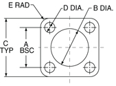
Part Number A Bsc. B Dia. C Typ. D Dia. E Rad. Shell Size Fluorosilicone Viton® Conductive In. MM In. MM In. MM In. MM In. MM 5 2M809-108F11 2M809-108V11 2M809-108X11 0.363 9.22 0.342 8.69 0.530 13.46 0.093 2.36 0.078 1.98 6 2M809-108F12 2M809-108V12 2M809-108X12 0.423 10.74 0.405 10.29 0.590 14.99 0.093 2.36 0.078 1.98 7 2M809-108F13 2M809-108V13 2M809-108X13 0.483 12.27 0.467 11.86 0.650 16.51 0.093 2.36 0.078 1.98 8 2M809-108F14 2M809-108V14 2M809-108X14 0.542 13.84 0.530 13.46 0.712 18.08 0.093 2.36 0.078 1.98 9 2M809-108F16 2M809-108V16 2M809-108X16 0.719 15.42 0.560 14.22 0.850 21.59 0.125 3.18 0.105 2.67 10 2M809-108F15 2M809-108V15 2M809-108X15 0.71 17.02 0.655 16.64 0.890 22.61 0.125 3.18 0.105 2.67 13 2M809-108F17 2M809-108V17 2M809-108X17 0.812 20.62 0.842 21.39 1.030 26.16 0.125 3.18 0.105 2.67 16 2M809-108F18 2M809-108V18 2M809-108X18 0.981 24.92 1.030 26.16 1.219 30.96 0.125 3.18 0.105 2.67 17 2M809-108F19 2M809-108V19 2M809-108X19 1.060 26.92 1.092 27.74 1.280 32.51 0.125 3.18 0.105 2.67 21 2M809-108F43 2M809-108V43 2M809-108X43 1.322 33.58 1.332 33.83 1.570 39.88 0.125 3.18 0.105 2.67 AMPHENOL 2M SERIES SHRINK BOOTS FOR INTEGRAL ENDBELL
High-Performance Elastomer Zero-Halogen Pre-Coated with High-Temperature Adhesive
Low-Smoke, Zero-Halogen Toxicity Requirements
Straight Boot Cable Range Right Angle Boot Cable Range High-Performance Elastomer Zero-Halogen Max. Min. Max. Min. Boot Size Shell Size Straight Right Angle Straight Right Angle IN. MM IN. MM IN. MM IN. MM 1 5 2M809S 2M809A 2M809S 2M809A 0.350 9.0 0.080 2.0 0.240 6.0 0.080 2.0 2 6, 7 2M809S 2M809A 2M809S 2M809A 0.650 16.5 0.150 3.8 0.650 16.5 0.100 2.5 3 8, 9 2M809S 2M809A 2M809S 2M809A 0.920 23.4 0.220 5.6 0.920 23.3 0.220 5.6 4 10, 13 2M809S 2M809A 2M809S 2M809A 1.120 28.4 0.260 6.6 1.120 28.5 0.250 6.3 5 16, 17 2M809S 2M809A 2M809S 2M809A 1.220 31.0 0.280 7.1 1.220 30.9 0.280 7.1 6 21 2M809S 2M809A 2M809S 2M809A 1.680 42.7 0.390 9.9 1.680 42.6 0.380 9.7 * Size 1 Zero-halogen right-angle supplied less lip, see graphic. AMPHENOL 2M SERIES DUSTCAPS
Metal Dustcaps with Nylon Rope Lanyard Shell Size for 2M801 For Plugs with Ring Attachment For Flanged Receptacles with Ring Attachment For Jam Nut Receptacles with Large Ring Attachement 5 2M667-217-XX-G502-4 2M667-218-XX-G501-3 2M667-218-XX-G514-4 6 2M667-217-XX-G602-4 2M667-218-XX-G601-3 2M667-218-XX-G615-4 7 2M667-217-XX-G702-4 2M667-218-XX-G701-3 2M667-218-XX-G716-4 8 2M667-217-XX-G802-4 2M667-218-XX-G801-3 2M667-218-XX-G816-4 9 2M667-217-XX-G902-4 2M667-218-XX-G902-3 2M667-218-XX-G917-4 10 2M667-217-XX-G1002-5 2M667-218-XX-G1002-3 2M667-218-XX-G1018-4 13 2M667-217-XX-G1302-5 2M667-218-XX-G1302-3 2M667-218-XX-G1319-4 16 2M667-217-XX-G1602-6 2M667-218-XX-G1602-3 2M667-218-XX-G1620-4 17 2M667-217-XX-G1702-6 2M667-218-XX-G1702-3 2M667-218-XX-G1721-4 21 2M667-217-XX-G2102-6 2M667-218-XX-G2102-3 2M667-218-XX-G1724-4 C = Aluminum/ Black Anodize (Non-Conductive) (RoHS) M = Aluminum/ Electroless Nickel (RoHS) NF = Aluminum/ Cadmium with Olive Drab Chromate MT = Aluminum/ Nickel-PTFE (Durmalon) (RoHS) Z1 = Stainless Steel/ Passivated ZM = Stainless Steel/Electroless Nickel (RoHS) ZN = Aluminum/ Zinc-Nickel with Olive Drab Chromate ZNU = Aluminum/ Zinc-Nickel with Black Chromate (RoHS) REPLACE XX WITH PLATING CODE STRAIN RELIEF CABLE CLAMP WITH ROTATABLE COUPLING
Shell Size Part Number Thread Size 2B Cable Entry Dia. 5 2M620MS065-XX05 .2500-32 UNEF 0.11 6 2M620MS065-XX06 .3125-32 UNEF 0.17 7 2M620MS065-XX07 .4375-28 UNEF 0.23 8 2M620MS065-XX08 .5000-28 UNEF 0.30 9 2M620MS065-XX09 .5625-24 UNEF 0.30 10 2M620MS065-XX10 .6250-24 UNEF 0.36 13 2M620MS065-XX12 .6875-24 UNEF 0.42 16 2M620MS065-XX14 .9375-20 UNEF 0.48 17 2M620MS065-XX15 .9375-20 UNEF 0.61 21 2M620MS065-XX17 1.1875-18 UNEF 0.86 C = Aluminum/ Black Anodize (Non-Conductive) (RoHS) M = Aluminum/ Electroless Nickel (RoHS) NF = Aluminum/ Cadmium with Olive Drab Chromate MT = Aluminum/ Nickel-PTFE (Durmalon) (RoHS) Z1 = Stainless Steel/ Passivated ZM = Stainless Steel/Electroless Nickel (RoHS) ZN = Aluminum/ Zinc-Nickel with Olive Drab Chromate ZNU = Aluminum/ Zinc-Nickel with Black Chromate (RoHS) REPLACE XX WITH PLATING CODE AMPHENOL 2M SERIES ADDITIONAL BACKSHELLS
Description Part Number Prefix Straight 90° 45°
2M440MS135 2M440ML135 2M440MK135 X X X
2M370MS038 2M370MA03 2M370MB038 X X X
2M380MS137 2M380MA137 2M380MB137 X X X
2M390MS077 2M390MA077 2M390MB077 X X X 2M 803AMPHENOL 2M SERIES 2 HOLE FLANGED GASKETS
Part Number A Bsc. B Dia. C Typ. D Dia. Shell Size Fluorosilicone Viton® Conductive In. MM In. MM In. MM In. MM 5 2M809-108F31 2M809-108V31 2M809-108X31 0.513 13.03 0.345 8.00 0.710 18.03 0.460 11.68 6 2M809-108F32 2M809-108V32 2M809-108X32 0.598 15.19 0.405 10.29 0.795 20.19 0.522 13.26 7 2M809-108F33 2M809-108V33 2M809-108X33 0.708 17.98 0.475 12.07 0.900 22.86 0.590 14.99 8 2M809-108F34 2M809-108V34 2M809-108X34 0.964 24.51 0.545 13.84 1.160 29.46 0.670 17.02 9 2M809-108F35 2M809-108V35 2M809-108X35 1.017 25.83 0.605 15.37 1.215 30.86 0.721 18.31 10 2M809-108F36 2M809-108V36 2M809-108X36 1.101 27.97 0.682 17.32 1.295 32.89 0.795 20.19 12 2M809-108F37 2M809-108V37 2M809-108X37 1.204 30.58 0.757 19.23 1.400 35.56 0.874 22.20 14 2M809-108F38 2M809-108V38 2M809-108X38 1.280 32.51 0.910 23.11 1.555 39.50 1.050 26.67 15 2M809-108F39 2M809-108V39 2M809-108X39 1.370 34.80 0.970 24.64 1.640 41.66 1.150 29.21 AMPHENOL 2M SERIES SHRINK BOOTS FOR INTEGRAL ENDBELL
High-Performance Elastomer Zero-Halogen Pre-Coated with High-Temperature Adhesive
Low-Smoke, Zero-Halogen Toxicity Requirements
Straight Boot Cable Range Right Angle Boot Cable Range High-Performance Elastomer Zero-Halogen Max. Min. Max. Min. Boot Size Shell Size Straight Right Angle Straight Right Angle IN. MM IN. MM IN. MM IN. MM 1 5 2M809S 2M809A 2M809S 2M809A 0.350 9.0 0.080 2.0 0.240 6.0 0.080 2.0 2 6, 7 2M809S 2M809A 2M809S 2M809A 0.650 16.5 0.150 3.8 0.650 16.5 0.100 2.5 3 8, 9 2M809S 2M809A 2M809S 2M809A 0.920 23.4 0.220 5.6 0.920 23.3 0.220 5.6 4 10, 12 2M809S 2M809A 2M809S 2M809A 1.120 28.4 0.260 6.6 1.120 28.5 0.250 6.3 5 14, 15 2M809S 2M809A 2M809S 2M809A 1.220 31.0 0.280 7.1 1.220 30.9 0.280 7.1 * Size 1 Zero-halogen right-angle supplied less lip, see graphic. AMPHENOL 2M SERIES DUSTCAPS
Metal Dustcaps with Nylon Rope Lanyard Shell Size for 2M803 For Plugs with Ring Attachment For Flanged Receptacles with Ring Attachment For Jam Nut Receptacles with Large Ring Attachement 5 2M660-082-XX-G502-4 2M660-083-XX-G501-3 2M660-083-XX-G514-4 6 2M660-082-XX-G602-4 2M660-083-XX-G601-3 2M660-083-XX-G615-4 7 2M660-082-XX-G702-4 2M660-083-XX-G701-3 2M660-083-XX-G716-4 8 2M660-082-XX-G802-4 2M660-083-XX-G801-3 2M660-083-XX-G817-4 9 2M660-082-XX-G902-4 2M660-083-XX-G902-3 2M660-083-XX-G918-4 10 2M660-082-XX-G1002-5 2M660-083-XX-G1002-3 2M660-083-XX-G1019-4 12 2M660-082-XX-G1202-5 2M660-083-XX-G1202-3 2M660-083-XX-G1219-4 14 2M660-082-XX-G1402-6 2M660-083-XX-G1402-3 2M660-083-XX-G1420-4 C = Aluminum/ Black Anodize (Non-Conductive) (RoHS) M = Aluminum/ Electroless Nickel (RoHS) NF = Aluminum/ Cadmium with Olive Drab Chromate MT = Aluminum/ Nickel-PTFE (Durmalon) (RoHS) Z1 = Stainless Steel/ Passivated ZM = Stainless Steel/Electroless Nickel (RoHS) ZN = Aluminum/ Zinc-Nickel with Olive Drab Chromate ZNU = Aluminum/ Zinc-Nickel with Black Chromate (RoHS) REPLACE XX WITH PLATING CODE AMPHENOL 2M SERIES STRAIN RELIEF CABLE CLAMP WITH ROTATABLE COUPLING
Shell Size Part Number Thread Size 2B Cable Entry Dia. 5 2M620MS065-XX05 .2500-32 UNEF 0.11 6 2M620MS065-XX06 .3125-32 UNEF 0.17 7 2M620MS065-XX07 .4375-28 UNEF 0.23 8 2M620MS065-XX08 .5000-28 UNEF 0.30 9 2M620MS065-XX09 .5625-24 UNEF 0.30 10 2M620MS065-XX10 .6250-24 UNEF 0.36 12 2M620MS065-XX12 .6875-24 UNEF 0.42 14 2M620MS065-XX14 .9375-20 UNEF 0.48 C = Aluminum/ Black Anodize (Non-Conductive) (RoHS) M = Aluminum/ Electroless Nickel (RoHS) NF = Aluminum/ Cadmium with Olive Drab Chromate MT = Aluminum/ Nickel-PTFE (Durmalon) (RoHS) Z1 = Stainless Steel/ Passivated ZM = Stainless Steel/Electroless Nickel (RoHS) ZN = Aluminum/ Zinc-Nickel with Olive Drab Chromate ZNU = Aluminum/ Zinc-Nickel with Black Chromate (RoHS) REPLACE XX WITH PLATING CODE AMPHENOL 2M SERIES ADDITIONAL BACKSHELLS
Description Part Number Prefix Straight 90° 45°
2M440MS135 2M440ML135 2M440MK135 X X X
2M370MS038 2M370MA03 2M370MB038 X X X
2M380MS137 2M380MA137 2M380MB137 X X X
2M390MS077 2M390MA077 2M390MB077 X X X 2M 804AMPHENOL 2M SERIES SHRINK BOOTS FOR INTEGRAL ENDBELL
High-Performance Elastomer Zero-Halogen Pre-Coated with High-Temperature Adhesive
Low-Smoke, Zero-Halogen Toxicity Requirements
Straight Boot Cable Range Right Angle Boot Cable Range High-Performance Elastomer Zero-Halogen Max. Min. Max. Min. Boot Size Shell Size Straight Right Angle Straight Right Angle IN. MM IN. MM IN. MM IN. MM 1 5 2M809S 2M809A 2M809S 2M809A 0.350 9.0 0.080 2.0 0.240 6.0 0.080 2.0 2 6, 7 2M809S 2M809A 2M809S 2M809A 0.650 16.5 0.150 3.8 0.650 16.5 0.100 2.5 3 8, 9 2M809S 2M809A 2M809S 2M809A 0.920 23.4 0.220 5.6 0.920 23.3 0.220 5.6 4 10, 12 2M809S 2M809A 2M809S 2M809A 1.120 28.4 0.260 6.6 1.120 28.5 0.250 6.3 5 14 2M809S 2M809A 2M809S 2M809A 1.220 31.0 0.280 7.1 1.220 30.9 0.280 7.1 * Size 1 Zero-halogen right-angle supplied less lip, see graphic. AMPHENOL 2M SERIES METAL DUSTCAPS
Metal Dustcaps with Nylon Rope Lanyard Shell Size for 2M804 For Plugs with Ring Attachment For Flanged Receptacles with Ring Attachment For Jam Nut Receptacles Rear Mount with Large Ring Attachement For Jam Nut Receptacles Front Mount with Large Ring Attachement 5 2M809-198-XX5-G02-4 2M667-202-XX5-G01-3R 2M667-202-XX5-G14-4R 2M667-202-XX5-G16-4R 6 2M809-198-XX6-G02-4 2M667-202-XX6-G01-3R 2M667-202-XX6-G15-4R 2M667-202-XX6-G16-4R 7 2M809-198-XX7-G02-4 2M667-202-XX7-G01-3R 2M667-202-XX7-G16-4R 2M667-202-XX7-G18-4R 8 2M809-198-XX8-G02-4 2M667-202-XX8-G01-3R 2M667-202-XX8-G16-4R 2M667-202-XX8-G18-4R 9 2M809-198-XX9-G02-4 2M667-202-XX9-G02-3R 2M667-202-XX9-G17-4R 2M667-202-XX9-G19-4R 10 2M809-198-XX10-G02-5 2M667-202-XX10-G02-3R 2M667-202-XX10-G18-4R 2M667-202-XX10-G19-4R 12 2M809-198-XX12-G02-5 2M667-202-XX12-G02-3R 2M667-202-XX12-G19-4R 2M667-202-XX12-G20-4R 14 2M809-198-XX14-G02-6 2M667-202-XX14-G02-3R 2M667-202-XX14-G20-4R 2M667-202-XX14-G20-4R C = Aluminum/ Black Anodize (Non-Conductive) (RoHS) M = Aluminum/ Electroless Nickel (RoHS) NF = Aluminum/ Cadmium with Olive Drab Chromate MT = Aluminum/ Nickel-PTFE (Durmalon) (RoHS) Z1 = Stainless Steel/ Passivated ZM = Stainless Steel/Electroless Nickel (RoHS) ZN = Aluminum/ Zinc-Nickel with Olive Drab Chromate ZNU = Aluminum/ Zinc-Nickel with Black Chromate (RoHS) REPLACE XX WITH PLATING CODE AMPHENOL 2M SERIES RUBBER DUSTCAPS
Rubber Non-Conductive Dustcaps with Nylon Rope Lanyard Shell Size for 2M804 For Plugs with Ring Attachment For Flanged Receptacles with Ring Attachment For Jam Nut Receptacles 5 2M809-083-5G4-02 2M809-087-5G4-15 2M809-087-5G4-08 6 2M809-083-6G4-02 2M809-087-6G4-08 2M809-087-6G4-16 7 2M809-083-7G4-02 2M809-087-7G4-17 2M809-087-7G4-18 8 2M809-083-8G4-02 2M809-087-8G4-17 2M809-087-8G4-18 9 2M809-083-9G4-02 2M809-087-9G4-18 2M809-087-9G4-10 10 2M809-083-10G5-02 2M809-087-10G4-10 2M809-087-10G4-25 12 2M809-083-12G5-02 2M809-087-12G4-19 2M809-087-12G4-12 14 2M809-083-14G6-02 2M809-087-14G4-12 2M809-087-14G4-20 AMPHENOL 2M SERIES STRAIN RELIEF CABLE CLAMP WITH ROTATABLE COUPLING
Shell Size Part Number Thread Size 2B Cable Entry Dia. 5 2M620MS065-XX05 .2500-32 UNEF 0.11 6 2M620MS065-XX06 .3125-32 UNEF 0.17 7 2M620MS065-XX07 .4375-28 UNEF 0.23 8 2M620MS065-XX08 .5000-28 UNEF 0.30 9 2M620MS065-XX09 .5625-24 UNEF 0.30 10 2M620MS065-XX10 .6250-24 UNEF 0.36 12 2M620MS065-XX12 .6875-24 UNEF 0.42 14 2M620MS065-XX14 .9375-20 UNEF 0.48 C = Aluminum/ Black Anodize (Non-Conductive) (RoHS) M = Aluminum/ Electroless Nickel (RoHS) NF = Aluminum/ Cadmium with Olive Drab Chromate MT = Aluminum/ Nickel-PTFE (Durmalon) (RoHS) Z1 = Stainless Steel/ Passivated ZM = Stainless Steel/Electroless Nickel (RoHS) ZN = Aluminum/ Zinc-Nickel with Olive Drab Chromate ZNU = Aluminum/ Zinc-Nickel with Black Chromate (RoHS) REPLACE XX WITH PLATING CODE AMPHENOL 2M SERIES ADDITIONAL BACKSHELLS
Description Part Number Prefix Straight 90° 45°
2M440MS135 2M440ML135 2M440MK135 X X X
2M370MS038 2M370MA03 2M370MB038 X X X
2M380MS137 2M380MA137 2M380MB137 X X X
2M390MS077 2M390MA077 2M390MB077 X X X 2M 805AMPHENOL 2M SERIES SQUARE FLANGED GASKETS
Part Number A Bsc. B Dia. C Typ. D Dia. E Rad. Shell Size Fluorosilicone Viton® Conductive In. MM In. MM In. MM In. MM In. MM 8 2M809-108F20 2M809-108V20 2M809-108X20 0.66 16.76 0.53 13.46 0.85 21.46 0.093 2.36 0.078 1.98 9 2M809-108F21 2M809-108V21 2M809-108X21 0.723 18.36 18.36 14.99 0.913 23.19 0.093 2.36 0.078 1.98 10 2M809-108F22 2M809-108V22 2M809-108X22 0.785 19.94 0.660 16.76 0.975 24.77 0.093 2.36 0.078 1.98 11 2M809-108F23 2M809-108V23 2M809-108X23 0.848 21.54 0.720 18.29 1.039 26.39 0.093 2.36 0.078 1.98 12 2M809-108F24 2M809-108V24 2M809-108X24 0.909 23.09 0.780 19.81 1.099 27.91 0.093 2.36 0.078 1.98 15 2M809-108F25 2M809-108F25 2M809-108X25 1.058 26.87 0.970 24.64 1.288 32.72 0.125 3.18 0.105 2.67 18 2M809-108F26 2M809-108V26 2M809-108X26 1.255 31.88 1.160 29.46 1.475 37.47 0.125 3.18 0.105 2.67 19 2M809-108F27 2M809-108V27 2M809-108X27 1.327 33.71 1.220 30.99 1.537 39.04 0.125 3.18 0.105 2.67 23 2M809-108F28 2M809-108V28 2M809-108X28 1.570 39.88 1.458 37.03 1.797 45.64 0.125 3.18 0.105 2.67 AMPHENOL 2M SERIES SHRINK BOOTS FOR INTEGRAL ENDBELL
High-Performance Elastomer Zero-Halogen Pre-Coated with High-Temperature Adhesive
Low-Smoke, Zero-Halogen Toxicity Requirements
Straight Boot Cable Range Right Angle Boot Cable Range High-Performance Elastomer Zero-Halogen Max. Min. Max. Min. Boot Size Shell Size Straight Right Angle Straight Right Angle IN. MM IN. MM IN. MM IN. MM 2 8, 9 2M809S 2M809A 2M809S 2M809A 0.650 16.5 0.150 3.8 0.650 16.5 0.100 2.5 3 10, 11 2M809S 2M809A 2M809S 2M809A 0.920 23.4 0.220 5.6 0.920 23.3 0.220 5.6 4 12, 15 2M809S 2M809A 2M809S 2M809A 1.120 28.4 0.260 6.6 1.120 28.5 0.250 6.3 5 18, 19 2M809S 2M809A 2M809S 2M809A 1.220 31.0 0.280 7.1 1.220 30.9 0.280 7.1 6 23 2M809S 2M809A 2M809S 2M809A 1.680 42.7 0.390 9.9 1.680 42.7 0.380 9.7 AMPHENOL 2M SERIES DUSTCAPS
Metal Dustcaps with Nylon Rope Lanyard Shell Size for 2M801 For Plugs with Ring Attachment For Flanged Receptacles with Ring Attachment For Jam Nut Receptacles with Large Ring Attachement 8 2M667-261-XX-G0802-4 2M667-262-XX-G0801-4 2M667-262-XX-G0816-4 9 2M667-261-XX-G0902-4 2M667-262-XX-G0901-4 2M667-262-XX-G0918-4 10 2M667-261-XX-G1002-5 2M667-262-XX-G1001-5 2M667-262-XX-G1018-5 11 2M667-261-XX-G1102-5 2M667-262-XX-G1101-5 2M667-262-XX-G1119-5 12 2M667-261-XX-G1202-5 2M667-262-XX-G1201-5 2M667-262-XX-G1219-5 15 2M667-261-XX-G1502-6 2M667-262-XX-G1502-5 2M667-262-XX-G1520-5 18 2M667-261-XX-G1802-6 2M667-262-XX-G1802-5 2M667-262-XX-G1822-5 19 2M667-261-XX-G1902-6 2M667-262-XX-G1902-5 2M667-262-XX-G1923-5 23 2M667-261-XX-G2302-6 2M667-262-XX-G2302-5 2M667-262-XX-G2325-5 C = Aluminum/ Black Anodize (Non-Conductive) (RoHS) M = Aluminum/ Electroless Nickel (RoHS) NF = Aluminum/ Cadmium with Olive Drab Chromate MT = Aluminum/ Nickel-PTFE (Durmalon) (RoHS) Z1 = Stainless Steel/ Passivated ZM = Stainless Steel/Electroless Nickel (RoHS) ZN = Aluminum/ Zinc-Nickel with Olive Drab Chromate ZNU = Aluminum/ Zinc-Nickel with Black Chromate (RoHS) REPLACE XX WITH PLATING CODE AMPHENOL 2M SERIES STRAIN RELIEF CABLE CLAMP WITH ROTATABLE COUPLING
Shell Size Part Number Thread Size 2B Cable Entry Dia. 8 2M620MS065-XX11 .2500-32 UNEF 0.11 9 2M620MS065-XX07 .3125-32 UNEF 0.17 10 2M620MS065-XX08 .4375-28 UNEF 0.23 11 2M620MS065-XX09 .5000-28 UNEF 0.30 12 2M620MS065-XX10 .5625-24 UNEF 0.30 15 2M620MS065-XX13 .6250-24 UNEF 0.36 18, 19 2M620MS065-XX14 .9375-20 UNEF 0.48 18, 19 2M620MS065-XX15 .9375-20 UNEF 0.61 23 2M620MS065-XX17 1.1875-18 UNEF 0.86 C = Aluminum/ Black Anodize (Non-Conductive) (RoHS) M = Aluminum/ Electroless Nickel (RoHS) NF = Aluminum/ Cadmium with Olive Drab Chromate MT = Aluminum/ Nickel-PTFE (Durmalon) (RoHS) Z1 = Stainless Steel/ Passivated ZM = Stainless Steel/Electroless Nickel (RoHS) ZN = Aluminum/ Zinc-Nickel with Olive Drab Chromate ZNU = Aluminum/ Zinc-Nickel with Black Chromate (RoHS) REPLACE XX WITH PLATING CODE AMPHENOL 2M SERIES ADDITIONAL BACKSHELLS
Description Part Number Prefix Straight 90° 45°
2M440MS135 2M440ML135 2M440MK135 X X X
2M370MS038 2M370MA03 2M370MB038 X X X
2M380MS137 2M380MA137 2M380MB137 X X X
2M390MS077 2M390MA077 2M390MB077 X X X |
|
WIRE STRIPPINGAMPHENOL 2M SERIES WIRE STRIPPING
Contact Size A 23, 20HD .150 (3.18) 20 .188 (4.77) 16 .188 (4.77) 12 .188 (4.77) All dimensions in inches (millimeters in parentheses) CONTACT CRIMPINGAMPHENOL 2M SERIES CONTACT CRIMPINGCorrect
STEP 1: Insert wire into rear of contact. Wire insulation must press against rear of contact. Wire must be visible through inspection hole. STEP 2: M22520 series crimp tool and locator is recommended. See Contact and Tool Table for choice of turret head and selection setting according to contact size, part number and wire gauge size. STEP 3: Insert contact and wire into tool jaws. To crimp, squeeze handles together fully until ratchet releases and allows handles to expand; otherwise, contact cannot be extracted from tool jaws. Maintain slight insertion pressure on wire while crimping contact to wire. CONTACT INSERTIONAMPHENOL 2M SERIES CONTACT INSERTION
STEP 1: Remove hardware from plug or receptacle and slip over wire bundle in proper order for reassembly. STEP 2: Using proper plastic or metal insertion tool for corresponding contact, position wire in tip of the tool so that the tool tip presses against the contact shoulder. STEP 3: Press tool against contact shoulder and, with firm and even pressure, insert wired contact and tool tip into center contact cavity.
STEP 4: When contact bottoms, a slight “click” can be heard as tines of metal retaining clip snap into place behind contact shoulder. STEP 5: Remove tool and pull back lightly on wire to make sure contact is properly seated. Repeat operation with remainder of contacts to be inserted, beginning with the center cavity and working outward in alternating rows. STEP 6: After all contacts are inserted, fill any empty cavities with wire sealing plugs. Reassemble plug or receptacle hardware. CONTACT EXTRACTIONAMPHENOL 2M SERIES CONTACT EXTRACTION
STEP 1: Remove hardware from plug or receptacle and slide hardware back along wire bundle. STEP 2: Using plastic or metal extraction tool with proper color code corresponding to contact size, place wire in tool. STEP 3: Insert tool into contact cavity until tool tip bottoms against the contact shoulder, expanding clip retaining tines.
STEP 4: Hold wire firmly in tool and extract wired contact and tool. Repeat operation for all contacts to be extracted. STEP 5: Fill any empty cavities with wire sealing plugs. Reassemble plug or receptacle hardware. |
Philadelphia
19116
Click here for the contact information of the branch nearest you.


