Amphenol 348 Series M81511 Connector
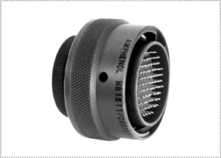
RELIABLE HIGH-DENSITY CONNECTORS
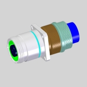
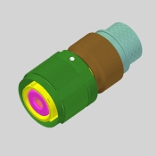
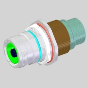
This Amphenol 348 Series M81511 connector provides reliability & high contact density. 348 Series is a commercial equivalent to MIL-C-81511, not qualified to MIL-C-81511, they accommodate a minimum of three circuits to a maximum of one hundred and fifty five circuits. The Amphenol 348 Series M81511 connector is available in two basic constructions: Long (Series I) & Standard (Series II). The Series I M81511 connector features 100% scoop-proof construction (potential contact damage minimized by recessed pins). The Series II M81511 connector are scoop-proof when pin contacts are specified in the receptacle shell only. Mil Spec connector part numbers begin M81511/. Amphenol Proprietary part numbers begin 348-.
|
AMPHENOL 348 SERIES (MIL-C-81511) SERIES MATERIALS & FINISHES
Pin Contact (standard) Copper base alloy, gold plated per 50 micro inches min. per MIL-G-45204 over suitable underplate.
Socket Contact (standard) Copper base alloy, gold plated per MIL-G-45204 over suitable underplate. Hood material is stainless steel.
Shell Aluminum alloy finish for E class connectors - cadmium plate over suitable underplate.
Inserts High grade dielectric material
AMPHENOL 348 SERIES (MIL-C-81511) SERIES ELECTRICAL DATA
Dielectric Withstanding Voltage Connectors shall show no evidence of breakdown or flashover when subjected to the test voltages and altitudes specified in table. Corona shall not be considered as breakdown. (Sea level tests performed per method 3001 of MIL-STD-1344; Altitude tests per method 1005, condition C, of MIL-STD-202).
Test Voltage (ac, rms, not working voltage)
Simulated Altitude Condition
Maximum recommended working voltage, ac, rms
AMPHENOL 348 SERIES (MIL-C-81511) SERIES MECHANICAL
Maintenance Aging All contacts shall be removed and installed for 10 cycles. After 10th cycle, contact insertion and retention forces are as shown in table:
Insertion Force lbs.
Maximum Removal Force lbs.
Minimum Removal Force lbs.
Maximum Locked Retention Force
lbs. Minimum
* Applies to both 23-28 and 23-22 contact sizes.
Durability After 500 mating-unmating cycles at a maximum rate of 300 cycles per hour, connectors shall not show any damage detrimental to the operation of the connector.
Corrosion After salt spray testing per method 1001, condition B, MIL-STD-1344 connectors shall show no exposure of basis metal which will affect performance.
Fluid Immersion Unmated connectors shall be immersed fully in fluids specified in table. At least one connector must be immersed in each fluid type. After the immersion period and a drying period of 1 hour, the connectors must remain completely functional.
Fluids for fluid immersion - Connector Class E MIL-H-5606, MIL-L-23699
Thermal Shock Connectors shall remain completely functional after being subjected to the temperature extremes specified below:
Low Temperature –65°C (+ 0°/– 3°) High Temperature –150°C (+ 3°/– 0°)
* Tested in accordance with method 1003, of MIL-STD-1344 per test conditions listed.
Vibration Connectors shall undergo vibration testing per method 2005, test condition IV, MIL-STD-1344 in low and high temperature extremes of preceding table with all contacts connected in series, and a current flow of 100 milliamperes. There shall be no circuit interruption longer than 1 micro-second.
Physical Shock The application of 1/2 sine-wave transient shock impulses of 50 gravity units to 3 planes for 11 milli-seconds, with test voltage applied to series connected contacts, shall result in no discontinuity longer than 1 micro-second. Connectors shall not be damaged, parts shall not become loose.
Temperature Life Mated connectors shall perform satisfactorily after being subjected to ambient temperatures specified, per class for 1000 hrs.
EMI Shielding Effectiveness As measured in a triaxial EMI leakage tester, connector shells with grounding springs shall exhibit a radio frequency attenuation equal to or greater than the following:
|
|
STEP 2: SELECT FINISH

RW = Olive Drab Chromate over Cadmium RB = Marine Nickel Aluminum Bronze
STEP 3: SELECT SHELL SIZE - AMPERAGE RATING

STEP 4: SELECT TERMINATION

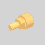
Threaded Post*
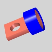
 Flat tail with cross hole*
 Tapped Hole woth locking flats*
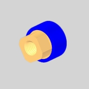
* Available for shell styles 00, 01, & 07 along with A style endbell
STEP 5: SELECT CONTACT

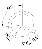
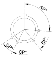
STEP 6: SELECT POLARIZATION

N = Normal Standard
A = Highly-Popular
B = Limited Availability
C = Check for Availability
D = Check for Availability
Receptacle Keyway Orientation
 Plug Key Orientation
STEP 7: SELECT ENDBELL TYPE

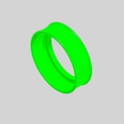
Locking Ring
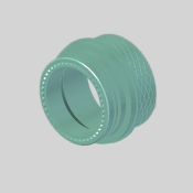
 Straight EMC Backshell with crimp termination types only
 Right Angle EMC Backshell with crimp termination types only
STEP 8: SELECT MODIFIER

W587 = Castellated Nut (for WPTV07 shell style only) W52 = Olive Drab Zinc Cobalt (with RW finish callout only) W638 = Panel Gasket supplied (for WPTV00 shell style only)
|


