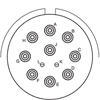
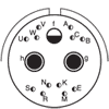
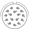
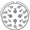
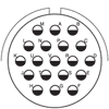
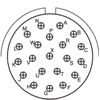
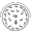
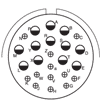
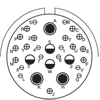
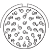
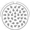
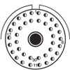
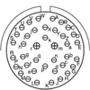
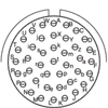
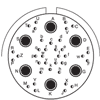
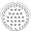
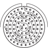
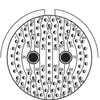
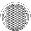
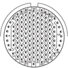
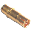
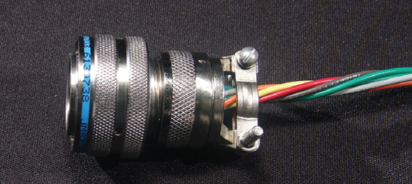
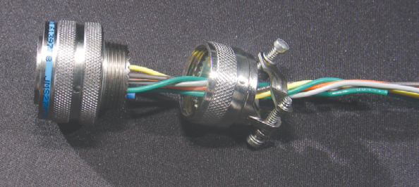
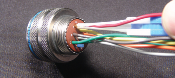
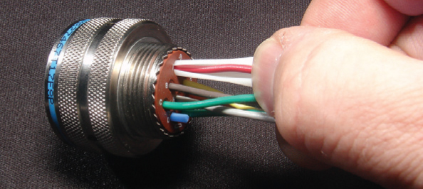
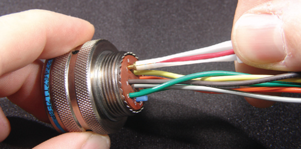
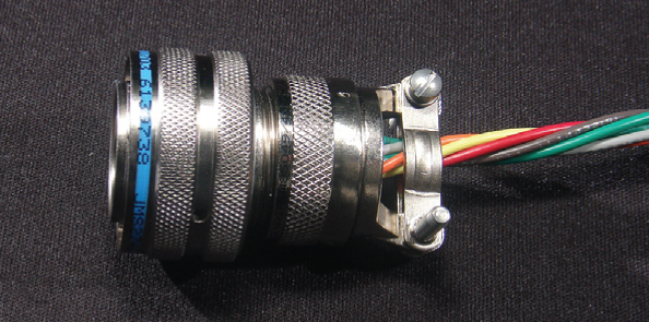
Amphenol Amphe-Lite™ 38999 Series III Type Connectors
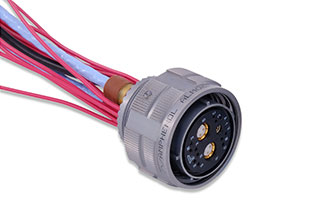
COMMERCIAL 38999 SERIES III TYPE INTERCONNECTS
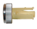
Amphenol Amphe-Lite™ are light-weight commercial 38999 Series III Type connectors that offer the highest performance capabilities for harsh environments, including communication towers and equipment, manufacturing process control and medical equipment. For full product details on Amphenol Amphe-Lite™ connectors, please see the specifications below.
Get shopping! Part numbers begin with AL.
|
FEATURESAMPHENOL AMPHE-LITE™ FEATURES
MATERIALS & FINISHESAMPHENOL AMPHE-LITE™ MATERIALS & FINISHES
Shell & Plating Composite, electroless nickel-plated and unplated (RoHS)
Contacts Copper alloy
Plating Gold-plated, 50 microinches per MIL-G-45204 type II, grade C, class I
Insulator Hard dielectric wafer which contains tines for high-reliability retention of crimp contacts
Grommet & Seals Fluorinated is standard or dimethyl silicone rubber elastomer
Grounding Springs Beryllium copper (grounded plug only)
ELECTRICAL DATAAMPHENOL AMPHE-LITE™ ELECTRICAL DATA
Contact Sizes 22D, 20, 16, 12, 10 and 8
Operating Voltage/Test Voltage Service Rating Test Voltages N M I II Sea Level 1000 1300 1800 2300 100,000 Feet 200 200 200 200 Current Rating by Contact Size & Wire Accommodation (Test Amps) Wire Size 22D 20 16 12 10 8 28 1.5 - - - - - 26 2.0 - - - - - 24 3.0 3.0 - - - - 22 5.0 5.0 - - - - 20 - 7.5 7.5 - - - 18 - - 10.0 - - - 16 - - 13.0 - - - 14 - - - 17.0 - - 12 - - - 23.0 - - 10 - - - - 33.0 - 8 - - - - - 46.0 Contact Resistance of Mated Contacts End-to-End Contact Size Maximum Millivolt Drop 22D 73 20 55 16 49 12 42 10 (power) 33 8 (power) 26 Insulation Resistance 5,000 megohms minimum
MECHANICALAMPHENOL AMPHE-LITE™ MECHANICAL
Operating Temperature -55°C to +125°C (-67°F to +248°F)
Sealing Against sand, dust per MIL-STD-202 & ice resistance
Wire Sealing Range Contact Size Minimum Inches Maximum Inches Minimum MM Maximum MM 22D 0.03 0.054 0.76 1.37 20 0.040 0.083 1.02 2.11 16 0.065 0.109 1.65 2.77 12 0.097 0.142 2.46 3.61 10 0.135 0.162 3.42 4.12 8 (power) 0.135 0.155 3.43 3.94 8 (co-ax) 0.135 0.155 3.43 3.94 8 (twinax) 0.124 0.134 3.15 3.40 Insulation Strip Length Contact Size Strip Length 22D .125 (3.18) 20 .188 (4.77) 16 .188 (4.77) 12 .188 (4.77) 10 .335 (8.51) 8 (power) .470 (11.94) Mating Life 500 cycles minimum
Salt Spray Electroless nickel only: 2000 hours min.
Temp. Durability Unplated and electroless nickel: UL RTI rating is 105°C (221°F)
EMI-Shielding Effectiveness 100 MHz to 10 GHz - minimum attenuation of 50dB
Contact Type Crimp, fibre optic, co-ax, twinax, or printed circuit
Number of Circuits 2 to 128
Contact Insertion Rear-insertion/rear-extraction with simple plastic or high-quality metal hand tools.
Contact Retention Contact Axial Load Newtons ±10% Axial Load Pounds ±10% 22D 44 10 20 67 15 16 111 25 12 111 25 10 111 25 8 111 25 Polarization Five keyways with optional master keyway rotations (Note: insert and main keyways remain fixed)
Approvals UL E115497
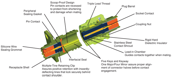
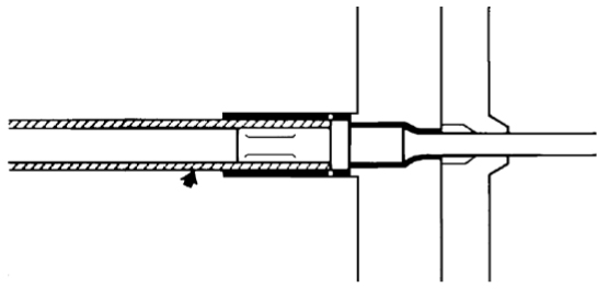
All dimensions in inches (millimeters in parentheses) CROSS-SECTION
|
|
AMPHENOL AMPHE-LITE™ APPLICATIONS
|
|
STEP 1: SHELLAMPHENOL AMPHE-LITE™ EXAMPLE
1 2 3 4 5 6 AL00 F 9-35 P A -LC SHELL STYLE FINISH LAYOUT CONTACT POLARIZATION MODIFIER STEP 1: SELECT SHELL STYLE, PLUG OR RECEPTACLE
AL00 AL07 AL06
STEP 2: CLASSSTEP 2: SELECT CLASS-SERVICE CLASS
(All classes are RoHS Compliant) F = Electroless nickel-plated composite shells, with fluorinated silicone rubber components (Brown-colored grommet) (RoHS) FD = Electroless nickel-plated composite shells, with dimethyl silicone rubber components. Not available on all inserts, see FD label†. (Blue or red-colored insert) (RoHS) U = Black composite, unplated with fluorinated silicone rubber components. (Brown-colored grommet) (RoHS) UD = Black composite, unplated with dimethyl silicone rubber components. Not available on all inserts, see UD label†.(Blue or red-colored insert) (RoHS) STEP 3: LAYOUTSTEP 3: SELECT LAYOUT
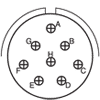
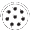
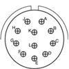
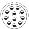
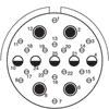
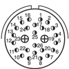
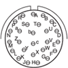
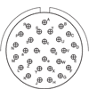
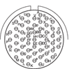
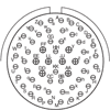
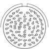
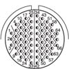
Contacts Layout Number Service Rating Total Number 22D 20 16 12 10 8 9-35 M 6 6 9-94 M 2 2 9-98 I 3 3 11-2† I 2 2 11-5 I 5 5 11-35† M 13 13 11-98† I 6 6 11-99 I 7 7 13-4† I 4 4 13-4† I 4 4 13-8† I 8 8 13-13† I, Fibre Optic 4 2 2 13-35 M 22 22 13-71† I 2 2 13-98† I 10 10 15-AC† M 26 24 2 15-5 II 5 5 15-15 I 15 14 1 15-18 I 18 18 15-19† I 19 19 15-35† M 37 37 15-97 I 12 8 4 17-2 M 39 38 1** 17-6 I 6 6 17-8† II 8 8 17-22 Coax 4 2 2* 17-26† I 26 26 17-31 M 19 4 11 4 17-35 M 55 55 17-99 I 23 21 2 19-11 II 11 11 19-31 M 15 12 1 2 19-32 I 32 32 19-35 M 66 66 21-11 I 11 11 21-16 II 16 16 21-35† M 79 79 21-39 I 39 37 2 21-41 I 41 41 21-41 I 41 41 21-75 M 4 4* 23-6 M 6 6* 23-21 II 21 21 23-35 M 100 100 23-53 I 53 53 23-54 M 53 40 9 4 23-55 I 55 55 25-4 I 56 48 8 25-7 Twinax 99 97 2** 25-8 I 8 8* 25-11 N 11 2 9 25-17 M 42 36 6** 25-19 I 19 19 25-20 N 30 10 13 4 3** 25-24 I 24 12 12 25-26 I 25 16 5 4** 25-29 I 29 29 25-35 M 128 128 25-43 I 43 23 20 25-46 I 46 40 4 2* 25-61 I 61 61 Note: Propriety connector 21-75 is supplied with size 8 Coax *Coax **Twinax Contact us for more information. †UD/FD-Type Insert Tooled Read Less LAYOUTS BY NUMBER OF CONTACTS
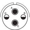
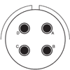
Contacts 2 3 4
Layout 9-94 11-2† 13-71† 9-98 13-4† 13-13† 17-22 # of Contacts 2-#20 2-#16 2-#12 3-#20 4-#16 2-#16, 2-#12 2-#12Q,* 2-#8Q* Service Rating M I I I I I, Fiber Optic Coax Contacts 4 5 6
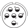
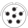
Layout 21-75 11-5 15-5 9-35 11-98† 17-6 # of Contacts 4-#8* 5-#20 5-#16 6-#22D 6-#20 6-#12 Service Rating M I II M I I Contacts 6 7 8
Layout 23-6 11-99 13-8† 17-8† 25-8 # of Contacts 6-#8** 7-#20 8-#20 8-#16 8-#8** Service Rating M I I II Twinax Contacts 10 11
Layout 13-98† 19-11 21-11 25-11 # of Contacts 10-#20 11-#16 11-#12 2-#20, 9-#10 Service Rating I II I N Contacts 12 13 15
Layout 15-97 11-35Ɨ 15-15 19-31 # of Contacts 8-#20, 4-#16 13-#22DƗ 14-#20,1-#16 12-#22D, 1-#12, 2-#8* Service Rating I M I M Contacts 16 18 19
Layout 21-16 15-18 15-19† 17-31 # of Contacts 16-#16 18-#20 19-#20† 4-#22D, 11-#20, 4- #16 Service Rating II I I† M Contacts 19 21 22 23
Layout 25-19 23-21 13-35 17-99 # of Contacts 19-#12 21-#16 22-#22D 21-#20, 2-#16 Service Rating I II M I Contacts 24 25 26
Layout 25-24 25-26 15-AC† 17-26† # of Contacts 12-#16, 12-#12 16-#20, 5-#12, 4-#8* 24-#22D, 2-#16 26-#20 Service Rating I I M I Contacts 29 30 32 37
Layout 25-29 25-20 19-32 15-35† # of Contacts 29-#16 10-#20, 13-#16, 4-#12*, 3-#8Q* 32-#20 37-#22D Service Rating I N I M Contacts 29 30 37
Layout 25-37 17-2 21-39 21-41 # of Contacts 37-#16 38-#22D, 1-#8** 37-#20;2-#16 41-#20 Service Rating I M I I Contacts 42 43 46
Layout 25-17 25-43 25-46 # of Contacts 36-#22D, 6-#8** 23-#20, 20-#16 40-#20, 4-#16, 2-#8* Service Rating M I I Contacts 53 55
Layout 23-53 23-54 17-35 23-55 # of Contacts 53-#20 40-#22D, 9-#16, 4-#12 55-#22D 55-#20 Service Rating I M M I Contacts 56 61 66 79
Layout 25-4 25-61 19-35 21-35† # of Contacts 48-#20, 8-#16 61-#20 66-#22D 79-#22D Service Rating I I M M Contacts 99 100 128
Layout 25-7 23-35 25-35 # of Contacts 97-#22D, 2-#8** 100-#22D 128-#22D Service Rating Twinax M M * Coax ** Twinax † UD/FD-Type Insert Tooled Contact us for more information. Read Less STEP 5: POLARIZATIONSTEP 5: SELECT POLARIZATION

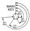
N = Normal Standard (Omit for normal) Receptacle Plug Minor Key Locations Shell Size AR & AP BR & BP CR & CP DR & DP
N A B C D E 105 102 80 35 64 91 140 132 118 140 155 131 215 248 230 205 234 197 265 320 312 275 304 240 B N 95 141 208 236 C A 113 156 182 292
B C D E 90 53 119 51 145 156 146 141 195 220 176 184 252 255 298 242 E N 80 142 196 293
A B C D E 135 49 66 62 79 170 169 140 145 153 200 200 200 180 197 310 244 257 280 272 G N 80 142 196 293 H A 135 170 200 310
B C D E 49 66 62 79 169 140 145 153 200 200 180 197 244 257 280 272 STEP 6: MODIFIERSTEP 6: MODIFIER

Omit for standard contacts LC = No contacts, sealing plugs or tools supplied NMG = Non-magnetic (Please contact us for availability) |
|
CONTACTSAMPHENOL AMPHE-LITE™ CONTACTS - PINS
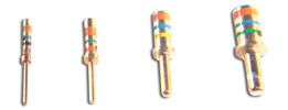
Contact Size Wire Size AWG Pin Contact Color Bands Color Bands Color Bands Wire Strip Lengths Wire Range Wire Range Wire Hole Filler Color 22D 22,24,26 & 28 M39029/ M39029/ Orange Blue Blue Red Black Black .125 (3.18) .030 (0.76) .054 (1.37) MS27488- Black 20 20,22 & 24 M39029/ M39029/ Orange Blue Blue Red Orange Brown .188 (4.77) .040 (1.02) .083 (2.11) MS27488- Red 16 16,18 & 20 M39029/ M39029/ Orange Blue Red Blue Yellow Red .188 (4.77) .065 (1.65) .109 (2.77) MS27488- Blue 12 12 & 14 M39029/ M39029/ Orange Blue Blue Red Green Orange .188 (4.77) .097 (2.46) .142 (3.61) MS27488-12-2 Yellow 10 10 & 12 M39029/ Green Red Grey .335 (8.51) .135 (3.42) .162 (4.12) M85049/ Green 8 Co-ax* M39029/ Orange Blue Violet Detailed instructions included with contacts .135 (3.42) .162 (4.12) MS27488-8-3 Red 8 Twinax** M39029/ Green Red White Detailed instructions included with contacts .124 (3.15) .134 (3.40) MS27488-8-3 Red 8 Power 8 10-497448-075 - - - .470 (11.94) .135 (3.42) .162 (4.12) MS27488-8-3 Red 8 Power 10 10-497448- - - - .470 (11.94) .135 (3.42) .162 (4.12) MS27488-8-3 Red AMPHENOL AMPHE-LITE™ CONTACTS - SOCKETS
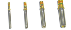
Contact Size Wire Size AWG Socket Contact Color Bands Color Bands Color Bands Wire Strip Lengths Wire Range Wire Range Wire Hole Filler Color 22D 22,24,26 & 28 M39029/ M39029/ Orange Blue Yellow Brown Grey Yellow .125 (3.18) .030 (0.76) .054 (1.37) MS27488- Black 20 20,22 & 24 M39029/ M39029/ Orange Blue Green Brown Brown Green .188 (4.77) .040 (1.02) .083 (2.11) MS27488- Red 16 16,18 & 20 M39029/ M39029/ Orange Blue Green Brown Red Blue .188 (4.77) .065 (1.65) .109 (2.77) 16-2
Blue 12 12 & 14 M39029/ M39029/ Orange Blue Green Brown Orange Violet .188 (4.77) .097 (2.46) .142 (3.61) MS27488- Yellow 10 10 & 12 M39029/ Green Red Violet .335 (8.51) .135 (3.42) .162 (4.12) M85049/ Green 8 Co-ax* M39029/ Orange Blue Blue Detailed instructions included with contacts .135 (3.42) .162 (4.12) MS27488-8-3 Red 8 Twinax** M39029/ Green Orange Black Detailed instructions included with contacts .124 (3.15) .134 (3.40) MS27488-8-3 Red 8 Power 8 10-497446-075 - - - .470 (11.94) .135 (3.42) .162 (4.12) MS27488-8-3 Red 8 Power 10 10-497446-095 - - - .470 (11.94) .135 (3.42) .162 (4.12) MS27488-8-3 Red Contact Color Codes 0 Black 1 Brown 2 Red 3 Orange 4 Yellow 5 Green 6 Blue 7 Violet 8 Gray 9 White #1500-Mating Cycle Contacts *Co-ax **Twinax contact us for details. For Fibre Optic Contacts, please contact us. All dimensions in inches (millimeters in parentheses) CONTACT TOOLSAMPHENOL AMPHE-LITE™ CONTACT TOOLS - PINS
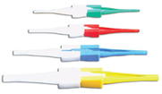
Contact Size Hand-Crimp Tool Power- Crimp Tool Turret Heads Use Locator Color Plastic Insertion/ Extraction Tool Insertion Tip Color Extraction Tip Color Metal Insertion Tool Color Band Metal Extraction Tool Color Band 22D M22520/ WA22 ƗƗ M22520/ - M81969/ Green White MS27495 Black MS27495 Black White 20 M22520/ WA27F
ƗƗ M22520/ Red M81969/ Red Orange MS27495 Red MS27495 Red White 16 M22520/ WA27F ƗƗ
M22520/ Blue M81969/ Blue White MS27495 Blue MS27495 Blue White 12 M22520/ WA2
7F ƗƗ M22520/ Yellow M81969/ Yellow White DAK95-12B - DRK95-12B - - 10 TP-201423 - - - M81969/ Grey White M81969/ Green M81969/ Green White 8 M22520/ WA22 ƗƗ M22520/2-31 (inner) M81969/ Green - - DRK264-8 - - 8 M22520/ WA22
K709 (inner) M81969/ Green M81969/ Red M81969/ - - 8 - 400B-1 414DA-8N (Die) - M81969/ - Green - - DRK264-8 - - 8 M3SP-6 400B-1 414DA-10N (Die) - M81969/ - Green - - DRK264-8 - - AMPHENOL AMPHE-LITE™ CONTACT TOOLS - SOCKETS
Contact Size Hand-Crimp Tool Power- Crimp Tool Turret Heads Use Locator Color Plastic Insertion/ Extraction Tool Insertion Tip Color Extraction Tip Color Metal Insertion Tool Color Band Metal Extraction Tool Color Band *22D M22520/ WA22 ƗƗ M22520/ - M81969/ Green White MS27495 Black MS27495 Black White 20 M22520/ WA27F
ƗƗ M22520/ Red M81969/ Red Orange MS27495 Red MS27495 Red White 16 M22520/ WA27F
ƗƗ M22520/ Blue M81969/ Blue White MS27495 Blue MS27495 Blue White 12 M22520/ WA2
7F ƗƗ M22520/ Yellow M81969/ Yellow White DAK95-12B - DRK95-12B - - 10 TP-201423 or 1716P-1 - - - M81969/ Grey White M81969/ Green M81969/ Green White 8 M22520/ WA22 ƗƗ
M22520/2-31 (inner) M81969/ Green - - DRK264-8 - - 8 M22520/ WA22
K709 (inner) M81969/ Green M81969/ Red M81969/ - - 8 - 400B-1 414DA-8N (Die) - M81969/ - Green - - DRK264-8 - - 8 M3SP-6 400B-1 414DA-10N (Die) - M81969/ - Green - - DRK264-8 - - ƗƗ Contact us for more tool accessories. Contact Color Codes 0 Black 1 Brown 2 Red 3 Orange 4 Yellow 5 Green 6 Blue 7 Violet 8 Gray 9 White CO-AX CONTACTSAMPHENOL AMPHE-LITE™ CO-AX CONTACTS
Co-ax Pin Co-ax Socket Crimping Tools
Co-ax Contact Size Cable Type Contact Part Number Contact Part Number Crimping Tools Crimping Tools
RG-178B/U, RG-174A/U, 21-033122-564
21-033123-564
RG-174A/U, RG-180B/U,
21-033122-541
21-033123-541
M22520/5-01 w/ die set M22520/5-05 (A)or M22520/5-19 (B) or M22520/10-01 w/ die set M22520/10-07 (A) M22520/5-01 w/ die set M22520/5-05 (B) or M22520/5-41 (B) or M22520/10-01 w/ die set M22520/10-07 (B)
M22520/2-01 w/ Positioner M22520/2-10
M22520/5-01 w/ die set M22520/5-45 (A)
Insertion / Extraction Tools Wire Strip Length Wire Sealing Range Co-ax Contact Size Installation Tools Installation Wire Strip Lengths Wire Sealing Range Wire Sealing Range 16 M81969/8-07 or M81969/8-08 or Contact us for details .065 (1.65) .109 (2.77) 12 M81969/8-09 or M81969/8-10 or Contact us for details .097 (2.46) .142 (3.61) 8 Hand-insertion M81969/14-012 or DRK264-8 or 11-9170 Contact us for details .135 (3.43) .155 (3.94) All dimensions in inches (millimeters in parentheses) PCB CONTACTSAMPHENOL AMPHE-LITE™ PRINTED CIRCUIT BOARD CONTACTS - PIN
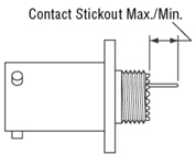
Contact Stickout Max./Min. PCB Pin Contacts Size Tail Dia. D38999/ TVP02 D38999/ D38999/ D38999/ 10-407552-015 22D 0.019 .335 /.280 .555 / .500 .360 / .305 .329 / .279 .286 / .236 10-407552-055 22D 0.019 .224 / .169 .444 / .389 .249 / .194 .218 / .168 .175 / .125 10-407552-085 22D 0.019 .060 / .010 .280 / .230 .085 / .035 .054 / .009 .011 / NS 10-407552-115 22D 0.019 .002 / NS .222 / NS .023 / NS NS NS 10-497640-015 20 0.019 .348 / .298 .568 / .518 .373 / .323 .342 / .297 .299 / .254 10-497640-025 20 0.019 .213 / .163 .433 / .383 .238 / .188 .207 / .162 .164 / .119 10-497640-045 20 0.019 NS NS NS NS NS 10-497596-015 20 0.025 .058 / .012 .278 / .232 .083 / .037 .052 / .011 .009 / .044 10-497596-025 20 0.025 .148 / .102 .368 / .322 .173 / .127 .142 / .101 .099 / .058 10-497596-035 20 0.025 .229 / .183 .449 / .403 .254 /.208 .223 / .182 .180 / .058 10-497596-055 20 0.025 .346 / .300 .566 / .520 .371 / .325 .340 / .299 .297 / .256 10-497695-015 16 0.040 .255 / .205 .475 / .425 .280 / .230 .249 / .204 .206 / .161 10-497630-035 16 0.062 .060 / .010 .280 / .230 .085 / .035 .054 / .009 .011 / NS 10-497630-055 16 0.062 .228 / .178 .460 / .375 .253 / .203 .244 / .177 .201 / .190 10-597502-015 12 0.081 .228 / .178 .448 / .398 .252 / .203 .222 / .177 .179 / .134 AMPHENOL AMPHE-LITE™ PRINTED CIRCUIT BOARD CONTACTS - SOCKET
Contact Stickout Max./Min. PCB Pin Contacts Size Tail Dia. D38999/ TVP02 D38999/ D38999/ D38999/ 10-597878-011 22D 0.019 .291 / .226 .511 / .446 .316 / .251 .285 / .222 .242 / .182 10-597878-331 22D 0.019 .242 / .181 .471 / .399 .267 / .202 .258 / .180 .215 / .155 10-497623-025 22D 0.019 .868 /.803 1.088 / 1.023 .893 / .828 .862 / .802 .819 / .759 10-597878-031 22D 0.019 .348 / .283 .568 / .503 .373 / .308 .342 / .282 .299 / .239 10-597878-041 22D 0.019 .208 / .143 .428 / .363 .233 / .168 .202 / .142 .159 / .099 10-597878-071 22D 0.019 .146 / .081 .366 / .301 .171 / .106 .140 / .080 .097 / .037 10-497623-145 22D 0.019 .609 / .539 .829 / .759 .634 / .564 .603 / .538 .560 / .495 10-597878-151 22D 0.019 .423 / .358 .643 / .578 .448 / .383 .417 / .357 .374 / .314 10-497643-015 20 0.019 .348 / .294 .568 / .514 .373 / .319 .342 / .293 .299 / .250 10-497643-025 20 0.019 .213 / .159 .433 / .379 .238 / .184 .207 / .158 .164 / .115 10-497643-035 20 0.019 .555 / .501 .775 / .721 .580 / .526 .549 / .500 .506 / .457 10-497650-015 16 0.040 .255 / .201 .475 / .421 .280 / .226 .249 / .200 .206 / .157 10-597503-015 12 0.081 .184 / .130 .404 / .350 .209 / .155 .178 / .129 .135 / .086 = Standard PC tail used |
|
RECEPTACLESAMPHENOL AMPHE-LITE™ RECEPTACLE - WALL MOUNTING AL00
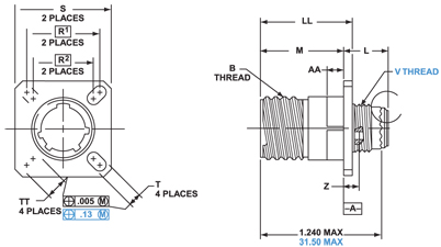
Shell Size B Thread Class 2A 1.0P-0.3L -TS (Plated) L Max. M +.000/ -.005 (+.000/ -.13) R1 R2 S Max. T +.008/ -.006 (+.20/ -.13) V Thread Metric Z Max. AA Max. Panel Thickness LL +/-.005 (+/-.13) TT +.008/ -.006 (+.20/ -.13) 9 .6250 .514 .775 .719 .594 .948 .128 M12X1-6g .198 .234 .913 .216 11 .7500 .514 .775 .812 .719 1.043 .128 M15X1-6g .198 .234 .913 .194 13 .8750 .514 .775 .906 .812 1.137 .128 M18X1-6g .198 .234 .913 .194 15 1.0000 .514 .775 .969 .906 1.232 .128 M22X1-6g .198 .234 .913 .173 17 1.1875 .514 .775 1.062 .969 1.323 .128 M25X1-6g .198 .234 .913 .194 19 1.2500 .514 .775 1.156 1.062 1.449 .128 M28X1-6g .198 .234 .913 .194 21 1.3750 .545 .745 1.250 1.156 1.575 .128 M31X1-6g .228 .204 .911 .194 23 1.5000 .545 .745 1.375 1.250 1.701 .154 M34X1-6g .228 .204 .911 .242 25 1.6250 .545 .745 1.500 1.375 1.823 .154 M37X1-6g .228 .204 .911 .242 AMPHENOL AMPHE-LITE™ RECEPTACLE - JAM NUT AL07
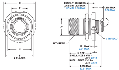
Shell Size A +.000/-.010 (+.00/-.25) B Thread Class 2A 0.1P-0.3L-TS (Plated) C Max. H Hex +.017/-.016 (+.43/-.41) S +/- .010 (+/-.25) T +.010/-.000 (+.25/-.00) V Thread Metric 9 .669 (16.99) 0.6250 1.199 (30.45) 0.875 (22.23) 1.062 (26.97) 0.697 (17.70) M12X1-6g 11 .669 (16.99) 0.6250 1.199 (30.45) 0.875 (22.23) 1.062 (26.97) 0.697 (17.70) M12X1-6g 13 0.955 (24.26) 0.8750 1.511 (38.38) 1.250 (30.18) 1.375 (34.93) 1.007 (25.58) M18X1-6g 15 1.084 (27.53) 1.0000 1.636 (41.55) 1.375 (33.32) 1.500 (38.10) 1.134 (28.80) M22X1-6g 17 1.208 (30.68) 1.1875 1.761 (44.73) 1.438 (36.53) 1.625 (41.28) 1.259 (31.98) M25X1-6g 19 1.333 (33.86) 1.2500 1.949 (49.50) 1.562 (39.67) 1.812 (46.02) 1.384 (35.15) M28X1-6g 21 1.459 (37.06) 1.3750 2.073 (52.65) 1.688 (42.80) 1.938 (49.23) 1.507 (38.28) M31X1-6g 23 1.575 (40.01) 1.5000 2.199 (55.85) 1.812 (46.02) 2.062 (52.37) 1.634 (41.50) M34X1-6g 25 1.709 (43.41) 1.6250 2.323 (59.00) 2.000 (50.80) 2.188 (55.58) 1.759 (44.68) M37X1-6g All dimensions in inches (millimeters in parentheses) PLUGSAMPHENOL AMPHE-LITE™ PLUG - STRAIGHT
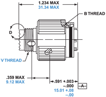
AL06
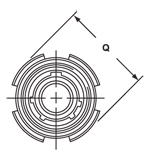
Shell Size B Thread Class2B 0.1P-0.3L-TS (Plated) Q Diameter Max. V Thread Metric 9 0.625 .858 (21.8) M12X1-6g 11 0.7500 .984 (25.0) M15X1-6g 13 0.8750 1.157 (29.4) M18X1-6g 15 1.0000 1.279 (32.5) M22X1-6g 17 1.1875 1.405 (35.7) M25X1-6g 19 1.2500 1.515 (38.5) M28X1-6g 21 1.3750 1.641 (41.7) M31X1-6g 23 1.5000 1.767 (44.9) M34X1-6g 25 1.6250 1.889 (48.0) M37X1-6g All dimensions in inches (millimeters in parentheses) PANEL CUTOUTS & THICKNESSAMPHENOL AMPHE-LITE™ PANEL CUTOUTS
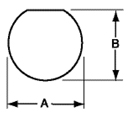
Wall Mount Receptacles Jam Nut Receptacles Shell Size D38999/20 & TV/CTV Wall Mount D38999/24 & D38999 TV/CTV G1 G2 H Diameter Front Mount Back Mount A +.010 (+.025) B +.000 (000) -.010 (-.025) A 9 .719 (18.26) .59 (15.09) .130 (3.25) .516 (13.11) .656 (16.66) .693 (17.60) .657 (16.70) B 11 .81 (20.62) .71 (18.26) .130 (3.25) .625 (15.88) .796 (20.22) .825 (20.96) .770 (19.59) C 13 .91 (23.01) .81 (20.62) .130 (3.25) .750 (19.05) .922 (23.42) 1.010 (25.65) .955 (24.26) D 15 .97 (24.61) .90 (23.01) .130 (3.25) .906 (23.01) 1.047 (26.59) 1.135 (28.83) 1.085 (27.56) E 17 1.06 (26.97) .96 (24.61) .130 (3.25) 1.016 (25.81) 1.219 (30.96) 1.260 (32.01) 1.210 (30.73) F 19 1.16 (29.36) 1.06 (26.97) .130 (3.25) 1.141 (28.98) 1.297 (32.94) 1.385 (35.18) 1.335 (33.91) G 21 1.25 (31.75) 1.15 (29.36) .130 (3.25) 1.266 (32.16) 1.422 (36.12) 1.510 (38.35) 1.460 (37.08) H 23 1.38 (34.93) 1.25 (31.75) .155 (3.94) 1.375 (34.93) 1.547 (34.93) 1.635 (41.53) 1.585 (40.29) J 25 1.50 (38.10) 1.37 (34.93) .155 (3.94) 1.484 (37.69) 1.672 (42.47) 1.760 (44.70) 1.710 (43.43) AMPHENOL AMPHE-LITE™ PANEL THICKNESS
AL00 - WALL MOUNT RECEPTACLE Rear Mount .125” (3.18) Max AL07 - JAM NUT RECEPTACLE .125” (3.18) Max/.062” (1.57) Min All dimensions in inches (millimeters in parentheses) |
|
DUMMY RECEPTACLES, DUST CAPS & PLUG CAPSAMPHENOL AMPHE-LITE™ DUMMY RECEPTACLES, DUST CAPS & PLUG CAPS
Plug Dust Caps Receptacle Dust Caps Nylon Braid Nylon Braid with Metal Ring Attached No Cord Nylon Braid Nylon Braid 6-inch Long with Metal Ring Attached Nylon Braid 3.5-inch Long with Metal Ring Attached C10-630910-XXX C10-630911-XXX C10-630912-XXX C10-630907-XXX C10-630908-XXX C10-630909-XXX Finish Suffix Electroless nickel -XXF Black composite, unplated -0XX XX = Insert shell size CABLE CLAMPSAMPHENOL AMPHE-LITE™ CABLE CLAMPS
Cable Clamp - Electroless Nickel Only Shell Size Straight Right Angle 9 C10-630934-09F C10-630935-09F 11 C10-630934-11F C10-630935-11F 13 C10-630934-13F C10-630935-13F 15 C10-630934-15F C10-630935-15F 17 C10-630934-17F C10-630935-17F 19 C10-630934-19F C10-630935-19F 21 C10-630934-21F C10-630935-21F 23 C10-630934-23F C10-630935-23F 25 C10-630934-25F C10-630935-25F Metric adaptors available. Please contact us. All dimensions in inches (millimeters in parentheses) |
|
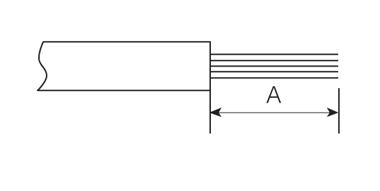
WIRE STRIPPINGAMPHENOL AMPHE-LITE™ WIRE STRIPPING
Contact Size A 22, 22M, 22D .125 (3.18) 20 .188 (4.77) 16 .188 (4.77) 12 .188 (4.77) 10 .335 (8.51) 8 (power) .470 (11.99) All dimensions in inches (millimeters in parentheses) CONTACT CRIMPINGAMPHENOL AMPHE-LITE™ CONTACT CRIMPING
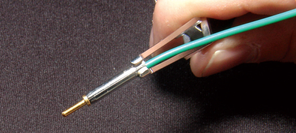
Correct
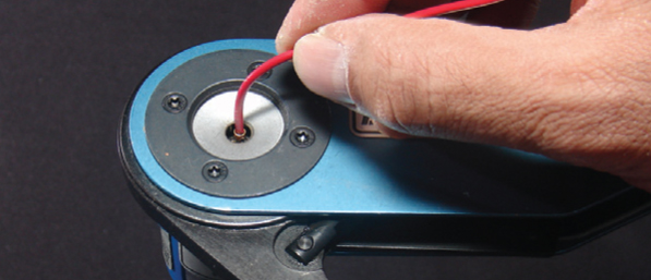
STEP 1: Insert wire into rear of contact. Wire insulation must press against rear of contact. Wire must be visible through inspection hole. STEP 2: See
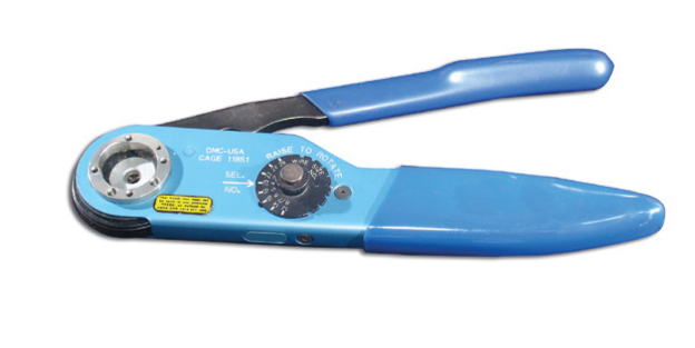
Contact and Tool Table for choice of turret head and selection setting according to contact size, part number and wire gauge size. STEP 3: Insert contact and wire into tool jaws. To crimp, squeeze handles together fully until ratchet releases and allows handles to expand; otherwise, contact cannot be extracted from tool jaws. Maintain slight insertion pressure on wire while crimping contact to wire. CONTACT INSERTIONAMPHENOL AMPHE-LITE™ CONTACT INSERTION
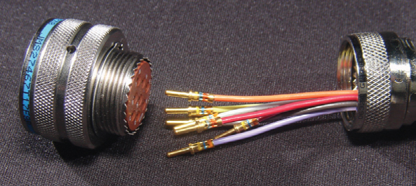
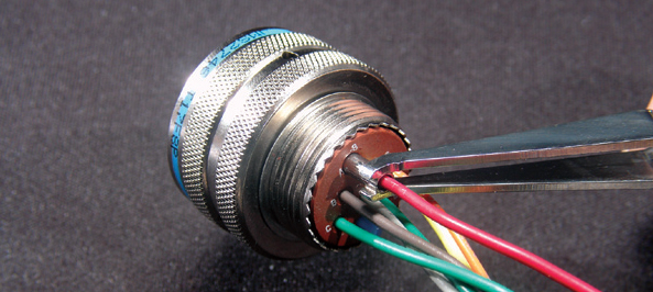
STEP 1: Remove hardware from plug or receptacle and slip over wire bundle in proper order for reassembly. STEP 2: Using proper plastic or metal insertion tool for corresponding contact, position wire in tip of the tool so that the tool tip presses against the contact shoulder. STEP 3: Press tool against contact shoulder and, with firm and even pressure, insert wired contact and tool tip into center contact cavity.
STEP 4: When contact bottoms, a slight “click” can be heard as tines of metal retaining clip snap into place behind contact shoulder. STEP 5: Remove tool and pull back lightly on wire to make sure contact is properly seated. Repeat operation with remainder of contacts to be inserted, beginning with the center cavity and working outward in alternating rows. STEP 6: After all contacts are inserted, fill any empty cavities with wire sealing plugs. Reassemble plug or receptacle hardware. CONTACT EXTRACTIONAMPHENOL AMPHE-LITE™ CONTACT EXTRACTION
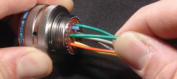
STEP 1: Remove hardware from plug or receptacle and slide hardware back along wire bundle. STEP 2: Using plastic or metal extraction tool with proper color code corresponding to contact size, place wire in tool. STEP 3: Insert tool into contact cavity until tool tip bottoms against the contact shoulder, expanding clip retaining tines.
STEP 4: Hold wire firmly in tool and extract wired contact and tool. Repeat operation for all contacts to be extracted. STEP 5: Fill any empty cavities with wire sealing plugs. Reassemble plug or receptacle hardware. Note: LJT Series shown. |
Philadelphia
19116
Click here for the contact information of the branch nearest you.


