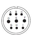
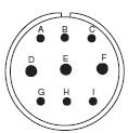
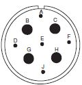
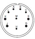
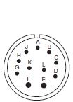
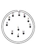
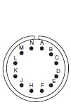
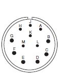
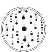
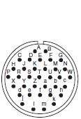
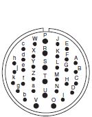
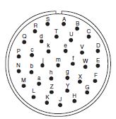
ITT Cannon CA Series MIL-DTL-5015 Connectors
RUGGED 5015 CONNECTOR FOR HARSH ENVIRONMENTS
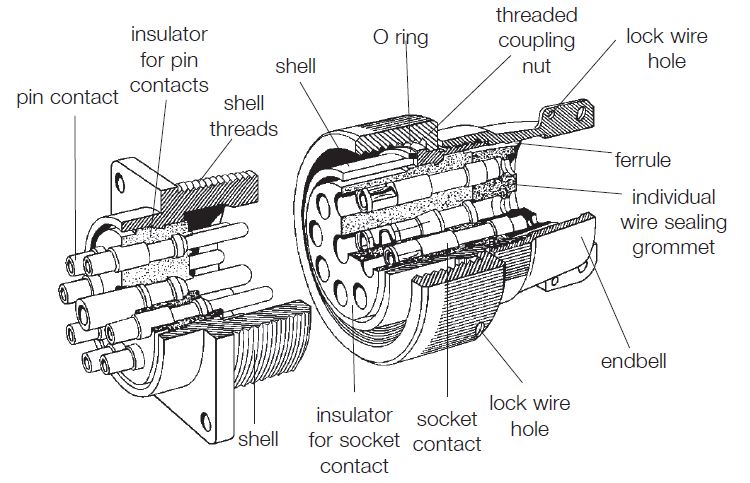
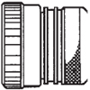
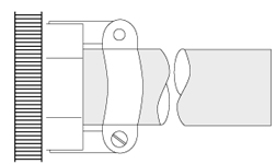
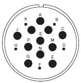
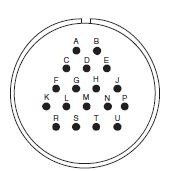
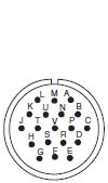
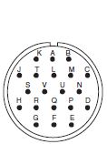
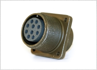
ITT Cannon CA series MIL-DTL-5015 connectors featured a threaded coupling mechanism and are manufactured to MIL-DTL-5015 for use in very harsh environments. ITT Cannon CA Series heavy duty 5015 connectors were originally designed as aerospace components and are popular, cost-effective, rugged commercial and military connectors. Hundreds of contact layouts are available, including common 2-pin connector, 3-pin connector, 4-pin connector, 12-pin connector and 16-pin connector types. The ITT Cannon CA series is a waterproof 5015 connector that is completely sealed to withstand condensation, vibration, and flash-over.
For full product details on the CA Series MIL-DTL- 5015 connectors, see the specifications below. Have a technical question? Click here to submit a technical request to our Design Engineers.
|
FEATURESITT CANNON CT SERIES MIL-DTL-5015 CONNECTORS FEATURES
MATERIALS & FINISHESITT CANNON CT SERIES MIL-DTL-5015 CONNECTORS — MATERIALS & FINISHES
Shell Aluminum Alloy (shells can be grounded)
Shell Plating Olive drab chromate coating over cadmium plating, black zinc cobalt, Blue Zinc Nickel, electroless Nickel.
Contacts Copper alloy
Contact Platings Hard silver or gold plating
Insulator* Resilient polychloroprene (Neoprene)
Seals Silicone or Neoprene
*Optional zero halogen and high temperature insulators are available. Contact us for information. ELECTRICAL DATAITT CANNON CT SERIES MIL-DTL-5015 CONNECTORS — ELECTRICAL DATA
Operating Voltage/Test Voltage According to MIL-DTL-5015 Operating Voltage Service Rating DC V AC Vrms Test Voltage Air Spacing Nom. Creepage Distance Nom. (Inches) I 250 200 1,000 - 1/16 A 700 500 2,000 1/16 1/8 D 1,250 900 2,800 1/8 3/16 E 1,750 1,250 3,500 3/16 1/4 B 2,450 1,750 4,500 1/4 5/16 NOTE: High Voltage Cartridge Contacts are available. These cartridges are used in either size 8 or 4 contact cavities using 20 AWG contact rated 7.5 amps max and working voltages up to 5000 Vdc - 3500 Vac. Contact us for details. Current Rating at 68°F (+20°C)
(CT) Max. Current Contact Resistance Milliohm Max. Potential Drop 16/16S 13 16 49 12 23 3 42 8 46 1 26 4 80 0.5 23 0 150 0.2 21 NOTE: CB and CT current rating are tested differently. Please contact us for information. Wire Range Sizes 26 AWG to 0 AWG
Insulation Resistance >5000 megaohms at 77°F (25°C) per MIL-DTL-5015, 3.18
MECHANICALITT CANNON CT SERIES MIL-DTL-5015 CONNECTORS — MECHANICAL
Operating Temperature -55° to 125°C (-67°F to 257°F) Neoprene
Sealing 48 hours in 6 feet of water per MIL-DTL-5015, 4.6.19. Meets 20-day extreme humidity testing per.
Wire Sealing Range The connector is designed for individual wire sealing. Sealing of an outer cable jacket on multiconductor cables must be accomplished with an appropriate endbell. Sealing is only guaranteed if wires according to MIL-W-5086 or within the listed ranges are used.
Insulation O.D. Limit (Inches) Contact Size Wire Size Min. (Inches) (MM) Max. (Inches) (MM) 16 16 .064 (1.63) .130 (3.30) 12 12 .114 (2.90) .170 (4.32) 8 8 .164 (4.17) .255 (6.48) 4 4 .275 (6.98) .370 (9.40) 0 0 .415 (10.54) .550 (13.97) Mating Life 100 cycles minimum. To MIL-DTL-5015, 3.16
Salt Spray CAD OD : MIL-STD-1344 Method 1001 Condition B. minimum.
A206 : 48 hours
Heat +125°C (+257°F) for 60 hours, +85°C (+185°F) for 1000 hours per MIL-DTL-5015, 4.6.14, minimum.
Chemical Resistance 20-hour full immersion unmated in hydraulic fluid and lubricating oil per MIL-DTL-5015 minimum.
Vibration 10 to 2,000Hz (15g’s) 10 microseconds maximum discontinuity. To MIL-STD-1344 Method 2005 per MIL-DTL-5015.
Shock 50g 11ms duration, three major axes. 10 microseconds maximum discontinuity. To MIL-DTL-5015, 3.13.
Contact Type Solder, crimp, PC, high voltage, first-mate last-break or thermocouple. Hard silver or gold plating.
Number of Circuits 1 to 65
Contact Insertion Solder contacts are bonded to insulator
Content Retention Pin and socket contacts are designed to resist severe vibration and repeated connection and disconnection.
Retention Force Separation Force Min. Axial Load Separation Force Min. Contact Size Newtons Lbs. Newtons Lbs. Gauge Newtons Lbs. Newtons Lbs. 16 35 (7.9) 1 (.22) G 1.56 44 (10) 1 (0.25) 12 55 (12.4) 1.5 (.34) G 2.36 67 (15) 2 (0.5) 8 80 (18.0) 3 (.67) G 3.58 89 (20) 4 (0.75) 4 90 (20.2) 4 (.90) G 5.69 89 (20) 4 (1) 0 95 (21.4) 8.5 (1.9) G 9.04 111 (25) 9 (2) Polarization Key and keyway with optional rotational polarization.
Approvals/Specifications • MIL-DTL-5015
|
|
ITT CANNON CT SERIES MIL-DTL-5015 CONNECTORS APPLICATIONS
Industrial environments requiring extreme environmental reliability and ease of mating and unmating, such as:
|
|
STEP 1 & 2: STYLEITT CANNON CT SERIES MIL-DTL-5015 CONNECTORS — PART NUMBER EXAMPLE
1 2 3 4 5 6 7 8 9 CT 6 E 10SL-3 P S CONNECTOR TYPE SHELL STYLE ENBELLS CABLE CLAMP/BOOT LAYOUT CONTACT POSITION CONTACT TYPE PLATING NOTE: For no Endbell/Backshell use "-" (hyphen). STEP 1: CHOOSE CONNECTOR TYPE
CT STEP 2: SELECT SHELL STYLE, PLUG OR RECEPTACLE
Barrel (EMI/RFI)
STEP 3: ENDBELLSSTEP 3: CHOOSE ENDBELLS
See "Endbells" section for a description of each endbell.
▲ Contact us with NPT thread size, Sealtite conduit diameter or cable OD for D, NPT, ST, PG or endbell part number. STEP 4: CLAMPSTEP 4: CHOOSE CABLE CLAMP (IF APPLICABLE)

▲ Contact us with NPT thread size, Sealtite conduit diameter or cable OD for D, NPT, ST, PG or endbell part number. STEP 5: LAYOUTSTEP 5: CHOOSE LAYOUT
Page 1
Series Contact Sizes Layout MS CT CB VG Total 20 16 12 8 4 0 8S-1
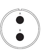
1 1 10S-2
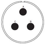
1 1 10SL-3
3 3 10SL-4
2 2 10SL-51
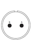
2 2 10SL-52
2 2 10SL-53
2 2 10SL-54
3 3 10SL-55
3 3 10SL-56
2 2 10SL-57
2 2 10SL-58
3 3 10SL-59
2 2 10SL-60
2 2 10SL-61
2 2 10SL-62
3 3 10SL-63
3 3 10SL-64
3 3 10SL-A4
5 5 12S-1
2 2 12S-2
2 2 12S-3
2 2 12S-4
1 1 12S-51
2 2 12S-54
2 2 12S-55
2 2 12S-56
2 2 12S-57
2 2 12S-58
2 2 12S-59
2 2 12S-60
2 2 12S-61
2 2 12S-62
2 2 12SA10
12-5
1 1 14S-1
3 3 14S-2
4 4 Degrees of Rotation Layout
W X Y Z Service Rating 8S-1 - - - - A 10S-2 - - - - A 10SL-3 - - - - A 10SL-4 - - - - A 10SL-51
10SL-4 45° A=Ir.; B=Con. 10SL-52
10SL-4 45° A=Cu; B=Con. 10SL-53
10SL-4 45° A=Al.; B=Ch. 10SL-54
10SL-3 A=Ir.; B=Con.; C=Cu 10SL-55
10SL-3 A=Al.; B=Ch.; C=Cu 10SL-56
10SL-4 A=Al.; B=Ch. 10SL-57
10SL-4 A=Ch.; B=Con. 10SL-58
10SL-3 A=Ch.; B=Cl.; C=Cu 10SL-59
10SL-4 A=Ch.; B=Al. 10SL-60
10SL-4 45° A=Ir.; B=Con. 10SL-61
10SL-4 A=Cu; B=Con. 10SL-62
10SL-3 A=Cu; B=Al.; C=Ir. 10SL-63
10SL-3 A, C=Con.; B=Ch. 10SL-64
10SL-3 A,C=Ch.; B=Al. 10SL-A4 Contact us for valid rotations A 12S-1 12S-3 100° A 12S-2 12S-3 250° A 12S-3 70 145 215 290 A 12S-4 - - - - D 12S-51
12S-3 315° A=Ch.; B=Al. 12S-54
12S-3 315° A=Ir.; B=Con. 12S-55
12S-3 45° A=Cu; B=Con. 12S-56
12S-3 A=Al.; B=Ch. 12S-57
12S-3 60° A=Ch.; B=Al. 12S-58
12S-3 120° A=Ir.; B=Con. 12S-59
12S-3 A=Ir.; B=Con. 12S-60
12S-3 A=Cu; B=Con. 12S-61
12S-3 A=Ch.; B=Con. 12S-62
12S-3 A=Ch.; B=Al. 12SA10 Contact us for valid rotations I 12-5 - - - - D 14S-1 - - - - A 14S-2 - 120 240 - I Contact Metallurgy Key: Alumel (Al.) Chromel (Ch.) Constantan (Con.) Copper (Cu) Iron (Ir.) Thermocouple ( Read Less Page 2
Series Contact Sizes Layout MS CT CB VG Total 20 16 12 8 4 0 14S-4
1 1 14S-5
5 5 14S-6
6 6 14S-7
3 3 14S-9
2 2 14S-10
4 4 14S-11
4 4 14S-12
3 3 14S-13
3 3 14S-14
4 4 14S-51
2 2 14S-52
4 4 14S-53
2 2 14S-54
6 6 14S-55
4 4 14S-56
4 4 14S-57
4 4 14S-58
3 3 14S-59
2 2 14S-60
2 2 14S-61
6 6 14S-63
6 6 14S-64
4 4 14S-65
6 6 14S-67
6 6 14S-68
4 4 14S-69
3 3 14S-70
4 4 14S-71
4 4 14S-72
2 2 14S-73
4 4 14S-74
4 4 14S-75
4 4 14S-76
4 4 14S-77
4 4 Degrees of Rotation Layout
W X Y Z Service Rating 14S-4 - - - - D 14S-5 - 110 - - I 14S-6 - - - - I 14S-7 90 180 270 - A 14S-9 70 145 215 290 A 14S-10 14S-2 100° I 14S-11 14S-2 250° I 14S-12 14S-1 100° A 14S-13 14S-1 260° A 14S-14 14S-2 260° I 14S-51
14S-9 90° A=Al; B=Ch. 14S-52
14S-2 45° A,B=Cu; C=Al; D=Ch. 14S-53
14S-9 90° A=Ir.; B=Con. 14S-54
14S-6 45° A,C,E=Ir.; B,D,F=Con. 14S-55
14S-2 45° A,C=Ir; B,D=Con. 14S-56
14S-2 45° A=Ir; B=Con.; C,D=Cu 14S-57
14S-2 45° A,C=Al; B,D=Ch. 14S-58
14S-7 90° A=Al; B=Ch.; C=Cu 14S-59
14S-9 90° A=Cu; B=Con. 14S-60
14S-9 A=Al; B=Ch. 14S-61
14S-6 45° A=Al; B=Ch.; C=Ir.; D=Con.; E,F=Cu 14S-63
14S-6 A,C=Al; B,D=Ch.; E=Ir.; F=Con. 14S-64
14S-2 A,C=Con; B,D=Cu 14S-65
14S-6 A,C,E=Cu; B,D,F=Con. 14S-67
14S-6 A=Al; B=Ch.; Balance=Cu 14S-68
14S-2 45° A=Ch; B=Con.; C,D=Cu 14S-69
14S-7 A=Con; B=Ch.; C=Cu 14S-70
14S-2 A,D=Ch; B,C=Al. 14S-71
14S-2 A,B,D=Cu; C=Con. 14S-72
14S-9 A=Con; B=Cu 14S-73
14S-2 A,B=Cu; C=Al.; D=Ch. 14S-74
14S-2 90° A,B=Ch; C,D=Al. 14S-75
14S-2 A,B=Cu; C,D=Con. 14S-76
14S-2 A,C=Al; B,D=Ch. 14S-77
14S-2 A,D=Al; B,C=Ch. Contact Metallurgy Key: Alumel (Al.) Chromel (Ch.) Constantan (Con.) Copper (Cu) Iron (Ir.) Thermocouple ( Read Less Page 3
Series Contact Sizes Layout MS CT CB VG Total 20 16 12 8 4 0 14S-78
2 2 14SA7
7 7 14-3
1 1 16S-1
7 7 16S-4
2 2 16S-5
3 3 16S-6
3 3 16S-8
5 5 16S-14
3 3 16S-15
2 2 16S-16
2 2 16S-17
3 3 16S-52
2 2 16S-54
7 7 16S-55
7 7 16SA18
7 7 16SA19
7 7 16SA20
7 7 16SA21
2 2 16-7
3 2 1 16-9
4 2 2 16-10
3 3 16-11
2 2 16-12
1 1 16-13
2 2 16-52
2 2 16-53
4 2 2 16-55
1 3 16-56
2 2 16-57
3 3 16-58
3 3 16-60
2 2 16-62
2 2 18-1
10 10 18-3
2 2 18-4
4 4 18-5
3 1 2 18-6
1 1 18-7
1 1 18-8
8 7 1 18-9
7 5 2 18-10
4 4 18-11
5 5 18-12
6 6 18-13
4 3 1 18-15
4 4 Degrees of Rotation Layout
W X Y Z Service Rating 14S-78
14S-9 A=Ch.; B=Al. 14SA7 - - - - A 14-3 - - - - A 16S-1 80 - - 280 A 16S-4 35 110 250 325 D 16S-5 70 145 25 290 A 16S-6 90 180 270 - A 16S-8 - 170 265 - A 16S-14
16S-4 110° A 16S-15 16S-5 110° D 16S-16 16S-4 2500° D 16S-17 16S-5 250° A 16S-52
16S-4 A=Ch.; B=Al. 16S-54
16S-1 A=Al.; B=Ch.; Balance=Cu 16S-55
16S-1 A=Con.; Balance=Cu 16SA18 16S-1 110° A 16SA19 16S-1 260° A 16SA20 16S-1 110° A 16SA21 16S-1 250° A 16-7 80 110 250 280 A 16-9 35 110 250 325 A 16-10 90 180 270 - A 16-11 35 110 250 325 A 16-12 - - - - A 16-13
35 110 250 325 A=Ir.; B=Con. 16-52
16-11 90° A=Al.; B=Ch. 16-53
16-9 70° A=Al.; C=Ch.; B,D=Cu 16-55
16-10 45° A=Al.; B=Ch.; C=Cu 16-56
16-13 90° A=Con.; B=Cu 16-57
16-10 A=Al.; B=Cu; C=Ch. 16-58
16-10 A=Con.; B,C=Cu 16-60
16-13 A=Al.; B=Ch. 16-62
16-11 A=Con.; B=Cu 18-1 70 145 215 290 A(B,C,F,G) 18-3 35 110 250 325 D 18-4 35 110 250 325 D 18-5 80 110 250 280 D 18-6 - - - - D 18-7 - - - - B 18-8 70 - - 290 A 18-9 80 110 250 280 I 18-10 - 120 240 - A 18-11 - 170 265 - A 18-12 80 - - 280 A 18-13 80 110 250 280 A 18-15
18-10 315° A,C=Ir.; B,D=Con. Contact Metallurgy Key: Alumel (Al.) Chromel (Ch.) Constantan (Con.) Copper (Cu) Iron (Ir.) Thermocouple ( Read Less Page 4
Series Contact Sizes Layout MS CT CB VG Total 20 16 12 8 4 0 18-17
7 5 2 18-18
7 5 2 18-19
10 10 18-20
5 5 18-21
3 3 18-22
3 3 18-23
10 10 18-24
10 10 18-25
2 2 18-26
2 2 18-27
3 1 2 18-28
3 1 2 18-29
5 5 18-30
5 5 18-31
5 5 18-51
6 6 18-52
5 5 18-53
6 6 18-54
4 4 18-56
10 10 18-57
6 6 18-59
6 6 18-60
5 5 18-61
6 6 18-62
6 6 18-63
4 4 18-65
6 6 18-66
10 10 18-67
6 6 18-68
5 5 18-69
10 10 18-70
5 5 18-71
4 4 18-72
4 4 18-73
7 5 2 18-74
6 6 Degrees of Rotation Layout
W X Y Z Service Rating 18-17 18-9 100° I 18-18 18-9 250° I 18-19 - 120 240 - A 18-20 90 180 270 - A 18-21 70 145 215 290 D 18-22 70 145 215 290 D 18-23 18-1 100° A(B,C,F,G) 18-24 18-1 250° A(B,C,F,G) 18-25 18-3 100° D 18-26 18-3 250° D 18-27 18-5 100° D 18-28 18-5 250° D 18-29 90 180 270 - A 18-30 18-20 110° A 18-31 18-20 260° A 18-51
18-12 A=Ir.; B,E=Con.; D=Cu; C,F=Dummy 18-52
18-11 A=Ir.; B=Con.; C=Ch; D=Al; E=Dummy 18-53
18-12 A=Ir.; B,E=Con.; D=Cu; C,F=Dummy 18-54
18-15 A,C=Con.; B,D=Cu 18-56
18-1 45° A,C,G,E,I=Ir.; B,D,F,H,J=Con. 18-57
18-12 45° A,C,E=Al.; B,D,F=Ch. 18-59
18-12 45° A,C=Ir.; B,E,F=Con.; D=Cu 18-60
18-11 45° A,D=Al.; B,C=Ch.; E=Cu 18-61
18-12 A,C=Ir.; B,D=Con.; E=Ch; E=Cu 18-62
18-1 A,B,C=Ir.; D,E,F=Con. 18-63
18-15 A,C=Con.; B,D=Cu 18-65
18-12 A=Ir.; B=Con.; Balance=Cu 18-66
18-1 A,C,E,G,I=Cu; B,D,F,H,J=Con. 18-67
18-12 A,C,E=Cu; B,D,F=Con. 18-68
18-11 A,D=Al.; B,C=Ch; E=Cu 18-69
18-1 A=Al.; B=Ch; Balance=Cu 18-70
18-11 A=Ir.; B=Con.; C=Ch; D=Al; E=Cu 18-71
18-15 A=Con.; Balance=Cu 18-72
18-15 D=Con.; Balance=Cu 18-73
18-9 A=Al.; D=Ch.; Balance=Cu 18-74
18-12 A=Ch.; B=Al.; D=Ir.; E=Cu; C,F=Con. Contact Metallurgy Key: Alumel (Al.) Chromel (Ch.) Constantan (Con.) Copper (Cu) Iron (Ir.) Thermocouple ( Read Less Page 5
Series Contact Sizes Layout MS CT CB VG Total 20 16 12 8 4 0 18A31
10 10 20-2
1 1 20-3
3 3 20-4
4 4 20-6
3 3 20-7
8 8 20-8
6 4 2 20-11
13 13 20-14
5 3 2 20-15
7 7 20-16
9 7 2 20-17
6 1 5 20-18
9 6 3 20-19
3 3 20-22
6 3 3 20-23
2 2 20-24
4 2 2 20-25
13 13 20-27
14 14 20-29
17 17 20-30
13 13 20-32
8 8 20-33
11 11 20-52
4 4 20-56
8 8 20-60
8 8 20-61
17 17 20-62
7 7 20-64
14 14 20-65
14 14 20-67
9 7 2 20-68
8 8 20-69
14 14 20-70
17 17 20-71
17 17 20-74
17 17 20-75
7 7 20-77
9 7 2 20-80
14 14 20-81
14 14 20-82
17 17 20A9
9 9 20A16
13 13 20A37
4 4 Degrees of Rotation Layout
W X Y Z Service Rating 18A31 18-1 110° A(B,C,F,G) 20-2 - - - - D 20-3 70 145 215 290 D 20-4 45 110 250 - D 20-6 70 145 215 290 D 20-7 80 110 250 280 A(B,C,F,G) 20-8 80 110 250 280 I 20-11 - - - - I 20-14 80 110 250 280 A 20-15 80 - - 280 A 20-16 80 110 250 280 A 20-17 90 180 270 - A 20-18 35 110 250 325 A 20-19 90 180 270 - A 20-22 80 110 250 280 A 20-23 35 110 250 325 A 20-24 35 110 250 325 A 20-25 20-11 100° I 20-27 35 110 250 325 A 20-29 80 - - 280 A 20-30 20-11 250° I 20-32 20-7 260° A(B,C,F,G) 20-33 - - - 280 A 20-52
20-4 315° A=Ir; B=Con; C=Ch; D=Al. 20-56
20-7 45° A,B,G,H=Ir; C,D,E,F=Con. 20-60
20-7 45° D=Ch; E=Al; Balance=Cu 20-61
20-29 45° A,B,M=Cu; Balance=Con 20-62
20-15 80° A,C,E=Al; B,D,F=Ch; G=Cu 20-64
20-27 A=Al; C=Ch; Balance=Cu 20-65
20-27 A,B,C,D,E,F,G=Ir; H,I,J,K,L,M,N=Con. 20-67
20-16 H=Al; I=Ch; Balance=Cu 20-68
20-7 A,B,G,H=Con; C,D,E,F=Cu 20-69
20-27 A,B,C,D,E,F,G=Cu; H,I,J,K,L,M,N=Con. 20-70
20-29 A,C,E,J,L,N,R,T=Ir; B,D,F,H,K,M,P,S=Con.=Ch; G=Cu 20-71
20-29 S=Al; R=Ch; Balance=Cu 20-74
20-29 A,C,E,G,J,L,N,R=Ir; B,D,F,H,K,M,P,S=Con; T=Cu 20-75
20-15 G=Al; Balance=Ch. 20-77
20-16 A=Con; Balance=Cu 20-80
20-27 A,C,E,G,I,K,M=Cu; B,D,F,H,J,L,N=Con. 20-81
20-27 A,C,E,G,I,K,M=Cu; B,D,F,H,J,L,N=Al 20-82
20-29 A,C,E,G,J,L,N,R=Al; B,D,F,H,K,M,P,S=Ch; T=Cu 20A9 - 110 250 - D(J), (all others) 20A16 20-11 182° I 20A37 20-4 250° D Contact Metallurgy Key: Alumel (Al.) Chromel (Ch.) Constantan (Con.) Copper (Cu) Iron (Ir.) Thermocouple ( Read Less Page 6
Series Contact Sizes Layout MS CT CB VG Total 20 16 12 8 4 0 20A48
19 19 22B22
4 4 22-1
2 2 22-2
3 3 22-4
4 2 2 22-5
19 19 22-6
3 1 2 22-7
1 1 22-8
2 2 22-9
3 3 22-10
4 4 22-11
2 2 22-12
5 3 2 22-13
5 1 4 22-14
19 19 22-15
6 1 5 22-16
9 6 3 22-17
9 8 1 22-18
8 8 22-19
14 14 22-20
9 9 22-21
3 2 1 22-22
4 4 22-23
8 8 22-27
9 8 1 22-28
7 7 22-30
19 19 22-31
2 2 22-32
6 4 2 22-57
19 19 22-60
19 19 22-62
8 8 22-68
14 14 22-69
14 14 22-71
19 19 22-72
6 4 2 Degrees of Rotation Layout
W X Y Z Service Rating 20A48 - 80 280 - I 22B22 - 110 250 - A 22-1 35 110 250 325 D 22-2 70 145 215 290 D 22-4 35 110 250 325 A 22-5 35 110 250 325 D 22-6 80 110 250 280 D 22-7 - - - - E 22-8 35 110 250 325 E 22-9 70 145 215 290 E 22-10 35 110 250 325 E 22-11 35 110 250 325 B 22-12 80 110 250 280 A 22-13 35 110 250 325 A(A-D) D(E) 22-14 80 - - 280 A 22-15 80 110 250 280 A(A-C,E,F) E(D) 22-16 80 110 250 280 A 22-17 80 110 250 280 D(A) 22-18 80 110 250 280 A(C-E 22-19 80 110 250 280 A 22-20 35 110 250 325 A 22-21 80 110 250 280 A 22-22 - 110 250 - A 22-23 35 - 250 - D(H) A(all others) 22-27 80 - 250 280 D(J) A(all others) 22-28 80 - - 280 A 22-30 22-14 100° A 22-31 22-11 100° B 22-32 22-5 260° D 22-57
22-14 45° A,C,E,G,J,L,N,R=Ir.; B,D,F,H,K,M,P,S=Con.; T,U,V=Cu 22-60
22-14 45° U=Al; N=Ch.; Balance=Cu 22-62
22-23 60° A,B,F,G=Al; C,D,E,H=Ch. 22-68
22-19 45° A,C,E,G,J,L,M=Ir.; B,D,F,H,K,P,N=Con. 22-69
22-19 45° A,C,E,G,J,L,M=Ir.; B,D,F,H,K,P,N=Cu 22-71
22-14 V=Al; U=Ch; Balance=Cu 22-72
22-5 B=Al; E=Ch; Balance=Cu Contact Metallurgy Key: Alumel (Al.) Chromel (Ch.) Constantan (Con.) Copper (Cu) Iron (Ir.) Thermocouple ( Read Less Page 7
Series Contact Sizes Layout MS CT CB VG Total 20 16 12 8 4 0 22-73
6 4 2 22-74
8 8 22-75
8 8 22-77
14 14 22-78
19 19 22-79
4 4 24-2
7 7 24-5
16 16 24-6
8 8 24-7
16 14 2 24-9
2 2 24-10
7 7 24-11
9 6 3 24-12
5 3 2 24-15
16 16 24-19
12 12 24-20
11 9 2 24-22
4 4 24-24
16 16 24-25
8 8 24-26
8 8 24-27
7 7 24-28
24 24 24-56
11 9 2 24-57
24 24 24-62
24 24 24-63
24 24 24-64
16 16 24-68
24 24 24-79 5 5 24-81
16 14 2 24A24
12 12 24A28
28 28 24A35
16 14 2 28-1
9 6 3 28-2
14 12 2 28-4
9 7 2 28-5
5 2 1 2 28-7
2 2 28-9
12 6 6 Degrees of Rotation Layout
W X Y Z Service Rating 22-73
22-5 E=Al; B=Ch; Balance=Cu 22-74
22-23 A,C,E,G=Ir; B,D,F,H=Con. 22-75
22-23 A=Al; B,D,G,H=Cu; C=Ch; E=Ir; C,G,N=Con. 22-77
22-19 B,D,F,H,J,K,M,P=Cu; A,E,L=Ir; C,G,N=Con. 22-78
22-14 A,C,E,G,H,K,M,P,R,T=Con.; Balance=Cu 22-79
22-10 A,C=Con; B,D=Cu 24-2 80 - - 280 D 24-5 80 110 250 280 A 24-6 80 110 250 280 D(A,G,H) 24-7 80 110 250 280 A 24-9 35 110 250 325 A 24-10 80 - - 280 A 24-11 35 110 250 325 A 24-12 80 110 250 280 A 24-15 24-5 100° A 24-19 - - - - A 24-20 80 110 250 280 D 24-22 45 110 250 - D 24-24 24-5 250° A 24-25 24-6 100° D(A,G,H) 24-26 24-6 250° D(A,G,H) 24-27 80 - - 280 E 24-28 80 110 250 280 I 24-56
24-20 45° E=Al; F=Ch; Balance=Cu 24-57
24-28 45° A,C,J,V,Y,W,K,E,H,U,S,M=Ch.; Balance=Al. 24-62
24-28 A,C,E,G=Ir; B,D,F,H=Con; R,T=Ch; S,U=Al; Balance=Cu 24-63
24-28 A,C,E,G,J,L,K,N,S,U,W,Y=Cu; B,D,F,H,Q,R,M,P,T,V,X,Z=Con. 24-64
24-5 A,B,C,D,E,F,G,H=Ir; J,K,L,M,N,P,R,S=Con. 24-68
24-28 D=Con; Balance=Cu 24-79 - - - - A 24-81
24-7 A,C,E,G,I,K,M,N,P=Cu; B,D,F,H,J,L,O=Con. 24A24 Contact us for valid rotations A 24A28 65 146 235 - I 24A35 24-7 100° A 28-1 80 110 250 280 D (A,E,J) 28-2 35 110 250 325 D 28-4 80 110 250 280 E (G,P,S) 28-5 35 110 250 325 D 28-7 35 110 250 325 D 28-9 80 110 250 280 D Contact Metallurgy Key: Alumel (Al.) Chromel (Ch.) Constantan (Con.) Copper (Cu) Iron (Ir.) Thermocouple ( Read Less Page 8
Series Contact Sizes Layout MS CT CB VG Total 20 16 12 8 4 0 28-10
7 3 2 2 28-11
22 18 4 28-12
26 26 28-13
26 26 28-14
11 11 28-15
35 35 28-16
20 20 28-17
15 15 28-19
10 6 4 28-20
14 4 10 28-21
37 37 28-22
6 3 3 28-51
12 12 28-53
22 18 4 28-58
14 4 10 28-59
17 10 7 28-61
37 37 28-63
14 4 10 28-64
35 35 28-65
26 26 28-67
20 20 28-68
35 35 28-69
22 18 4 28-70
22 18 4 28-77
22 18 4 28-81
37 37 28A16
9 5 4 28A51
43 43 28A63
28 19 9 32-1
5 3 2 32-2
5 2 3 Degrees of Rotation Layout
W X Y Z Service Rating 28-10 80 110 250 280 D(G) A(all others) 28-11 80 110 250 280 A 28-12 90 180 270 - A 28-13 28-12 100° A 28-14 80 110 250 280 D 28-15 80 110 250 280 A 28-16 80 110 250 280 A 28-17
80 110 250 280 A(A-L) B(R) 28-19 80 110 250 280 A(C,E,G,J,K,L) 28-20 80 110 250 280 A 28-21 80 110 250 280 A 28-22 70 145 215 290 D 28-51 80 135 195 - A 28-53
28-11 45° J,L=Al; K,M=Ch; Balance=Cu 28-58
28-20 45° A,C,E,G,K,M=Al; B,D,F,HL,N=Ch; J,P=Cu 28-59 - - - - A 28-61
28-21 45° A,C,J,Z,m,r,n,a,K,F,H,X,k,h,T,M,N,d=Ir; Balance=Cu 28-63
28-20 45° A,C,E,G,J=Al; B,D,F,H,P=Ch; Balance=Cu 28-64
28-15 A,d=Al; B,j=Ch; C,D,E,F,G,N,P,R,S,H,J,K,L,M,W,X,Y,Z=Con; Balance=Cu 28-65
28-12 A,C,E,G,J,L,N,R,T,V=Ir; X,Z=Al; B,D,F,H,K,M,P,S,U,W=Con; Y,a=Ch; b,d=Cu 28-67
28-16 U=Con; Balance=Cu 28-68
28-15 45° T=Al; U=Ch; Balance=Cu 28-69
28-11 G=Al; R=Ch; Balance=Cu 28-70
28-11 A=Al; B=Ch; Balance=Cu 28-77
28-11 J=Con; Balance=Cu 28-81
28-21 A,D,S,Z,n,s=Ir; B,J,Kf,g,r=Con; G,L,P,b,e,j=Al; F,H,T,X,h,k=Ch; Balance=Cu 28A16 Contact us for valid rotation A(E) I(all over) 28A51 Contact us for valid rotation A 28A63 - 110 260 - A 32-1 80 110 250 280 E(A) D(all others) 32-2 70 145 215 290 E Contact Metallurgy Key: Alumel (Al.) Chromel (Ch.) Constantan (Con.) Copper (Cu) Iron (Ir.) Thermocouple ( Read Less Page 9
Series Contact Sizes Layout MS CT CB VG Total 20 16 12 8 4 0 32-5
2 2 32-6
23 16 2 3 2 32-7
35 28 7 32-8
30 24 6 32-9
14 12 2 32-13
23 18 5 32-15
8 6 2 32-17
4 4 32-19
5 3 2 32-20
23 16 2 3 2 32-51
30 24 6 32-55
30 24 6 32A10
54 54 32A29
23 16 2 3 2 32A30
5 3 2 32A47
47 47 32A55
55 55 32A69
61 41 20 36-3
6 3 3 36-4
3 3 36-5
4 4 36-6
6 4 2 36-7
47 40 7 36-8
47 46 1 36-9
31 14 14 2 1 36-10
48 48 36-11
48 48 36-12
48 48 36-14
16 6 5 5 36-15
35 35 36-16
47 40 7 36-17
47 40 7 36-18
31 14 14 2 1 36-21
31 14 14 2 1 36-53
47 40 7 36A34
52 52 36A35
8 4 4 36A46
27 27 36A98
39 31 8 36A99
65 50 15 36A70
16 5 11 Degrees of Rotation Layout
W X Y Z Service Rating 32-5 35 110 250 325 D 32-6 80 110 250 280 A 32-7 80 125 235 280 I(A,B,H,J) 32-8 80 125 235 280 A 32-9 80 110 250 280 D 32-13 80 110 250 280 D 32-15 35 110 250 280 D 32-17 45 110 250 - D 32-19 32-1 260° 280 E(A) D(all others) 32-20 32-1 260° 280 A 32-51
32-8 90° M=Ch; N=Al; Balance=Cu 32-55
32-8 125° M,N=Ch; O,P=Al; Balance=Cu 32A10 Contact us for valid rotations A 32A29 32-6 250° A 32A30 32-1 100° E(A) D(all others) 32A47 Contact us for valid rotations A 32A55 80 110 250 280 A 32A69 - 110 250 - I 36-3 70 145 215 290 D 36-4 70 145 215 290 A(B,C) D(A) 36-5 45 110 240 - A 36-6 35 110 250 325 A 36-7 80 110 250 280 A 36-8 80 110 250 280 A 36-9 80 125 235 280 A 36-10 80 125 235 280 A 36-11 36-10 100° A 36-12 36-10 250° A 36-14 90 180 270 - D 36-15 60 125 245 305 D(m) A(all others) 36-16 36-7 100° 36-17 36-7 250° A 36-18 36-9 100° A 36-21 36-9 260° A 36-53
36-7 45° u,v,w=Al; x,y,z=Ch; Balance=Cu 36A34 Contact us for valid rotations A 36A35 Contact us for valid rotations A 36A46 Contact us for valid rotations A 36A98 Contact us for valid rotations I 36A99 Contact us for valid rotations I 36A70 - - - - I Contact Metallurgy Key: Alumel (Al.) Chromel (Ch.) Constantan (Con.) Copper (Cu) Iron (Ir.) Thermocouple ( Read Less LAYOUTS BY NUMBER OF CONTACTS
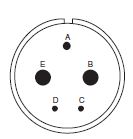
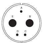
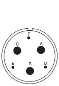
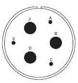
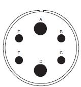
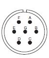
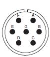
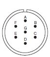
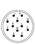
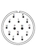
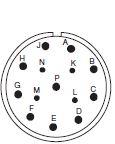
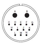
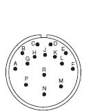
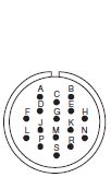
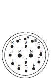
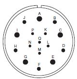
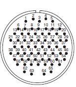
View from mating face of pin insulator * = Most Popular 1 Contact
Layout 8S-1 10S-2 12S-4 12-5 14S-4 16-12 18-6 18-7 20-2 22-7 # of Contacts 1-#16 1-#16 1-#16 1-#12 1-#16 1-#4 1-#4 1-#8 1-#0 1-#0 Series
Service Rating A A D D D A D B D E 2 Contacts
Layout 10SL-4* 12S-3* 14S-9* 16S-4 16-11 18-3 20-23 # of Contacts 2-#16 2-#16 2-#16 2-#16 2-#12 2-#12 2-#8 Series
Service Rating A A D A A D A
Layout 22-1 22-8 22-11 24-9 28-7 32-5 # of Contacts 2-#8 2-#12 2-#16 2-#4 2-#4 2-#0 Series
Service Rating D E B A D D 3 Contacts
Layout 10SL-3* 14S-1 14S-7* 16S-5 16S-6 16-7 16-10* 18-5 18-21 18-22 # of Contacts 3-#16 3-#16 3-#16 3-#16 3-#16 2-#16; 1-#8 3-#12 1-#16; 2-#12 3-#12 3-#16 Series
Service Rating A A A A A A A D D D
Layout 20-3 20-6 20-19 22-2 22-6 22-9 22-21 36-4 # of Contacts 3-#12 3-#16 3-#8 3-#8 1-#16; 2-#8 3-#12 2-#16; 1-#0 3-#0 Series
Service Rating D D A D D E A D(A) 4 Contacts
Layout 12SA-10 14S-2* 16-9 18-4* 18-10* 18-13 20-4* 20-24 22-4 # of Contacts 4-#16 4-#16 2-#16; 2-#12 4-#16 4-#12 3-#12; 1-#8 4-#12 2-#16; 2-#8 2-#12; 2-#8 Series
Service Rating I I A D A A D A A
Layout 22-10 22-22* 24-4 24-22* 32-17 36-5 # of Contacts 4-#16 4-#8 3-#16; 1-#0 4-#8 4-#4 4-#0 Series
Service Rating E A D D D A 5 Contacts
Layout 10SLA4 14S-5* 16S-8* 18-11* 18-20 20-14 22-12 22-13 24-12 # of Contacts 5-#20 5-#16 5-#16 5-#12 5-#16 3-#12; 2-#8 3-#16; 2-#8 1-#16; 4-#12 3-#12; 2-#4 Series
Service Rating A I A A A A D A(A,D); D(E) A 5 Contacts (cont.) 6 Contacts
Layout 28-5 32-1 14S-6* 18-12 20-8 20-17 20-22 # of Contacts 2-#16; 1-#12; 2-#4 3-#12; 2-#0 6-#16 6-#16 4-#16; 2-#8 1-#16; 5-#12 3-#16; 3-#8 Series
Service Rating D E(A); D(balance) I A I A A
Layout 22-5 22-15 28-22 36-3 36-6 # of Contacts 4-#16; 2-#12 1-#16; 5-#12 3-#16; 3-#4 3-#12; 3-#0 4-#4; 2-#0 Series
Service Rating D A(A,B,C,E,F); E(D) D D A 7 Contacts
Layout 14SA7 16S-1* 18-9 20-15* 22-28 24-2 24-10 24-27 28-10 # of Contacts 7#16 7-#16 5-#16; 2-#12 7-#12 7-#12 7-#12 7-#8 7-#16 3-#12; 2-#8; 2-#4 Series
Service Rating I A I A A D A E D(G); A(balance) 8 Contacts
Layout 18-8* 20-7* 22-18 22-23 24-6 32-15 36A35 # of Contacts 7-#16; 1-#12 8-#16 8-#16 8-#12 8-#12 6-#12; 2-#0 4-#16; 4-#0 Series
Service Rating A A(C-F); D(balance) A(C-E) D(H); A(balance) D(A,G,H); A(balance) D A 9 Contacts
Layout 20A9 20-16 20-18* 22-16 22-17 22-20 22-27 # of Contacts 9-#12 7-#16; 2-#12 6-#16; 3-#12 6-#16; 3-#12 8-#16; 1-#12 9-#16 8-#16; 1-#8 Series
Service Rating D(J); all others I A A A D(A); A(balance) A D(J); A(balance) 9 Contacts 10 Contacts
Layout 24-11* 28-1 28A16 18-1* 18-19 28-19 # of Contacts 6-#12; 3-#8 6-#12; 3-#8 5-#16; 4-#4 10-#16 10-#16 6-#16; 4-#12 Series
Service Rating A D(A,E,J); A(balance) A A(B,C,F,G); I(balance) A A(A,C,E,J,K,L); B(H,M); D(A,B) 11 Contacts 12 Contacts
Layout 20-33 24-20 28-14 24-19 24A24 28-9 28-51 # of Contacts 11-#16 9-#16; 2-#12 11-#16 12-#16 12-#12 6-#16; 6-#12 12-#12 Series
Service Rating A D D A A D D 13 Contacts 14 Contacts
Layout 20-11 20-27* 22-19* 28-2 28-20 32-9 # of Contacts 13-#16 14-#16 14-#16 12-#16; 2-#12 4-#16; 10-#12 12-#16; 2-#4 Series
Service Rating I A A D A D 15 Contacts 16 Contacts
Layout 28-17* 24-5 24-7* 36-14 36A70 # of Contacts 15-#16 16-#16 14-#16; 2-#12 6-#16; 5-#12; 5-#8 5-#16; 11#4 Series
Service Rating A(A-L); B(R); D(M-P) A A D - 17 Contacts 18 Contacts 19 Contacts
Layout 20-29* 36A16 20A48 22-14* # of Contacts 17-#16 18-#12 19-#16 19-#16 Series
Service Rating A A I A 20 Contacts 22 Contacts 23 Contacts
Layout 28-16 28-11* 32-6 32-13 # of Contacts 20-#16 18-#16; 4-#12 16-#16; 2-#12; 3-#8; 2-#4 18-#16; 5-#12 Series
Service Rating A A A D 24 Contacts 26 Contacts 27 Contacts 28 Contacts
Layout 24-28* 28-12* 36A46 24A28 28A63 # of Contacts 24-#16 26-#16 27-#12 28-#16 9-#12; 19-#16 Series
Service Rating I A A I A 30 Contacts 31 Contacts 35 Contacts
Layout 32-8 36-9 28-15* 32-7* # of Contacts 24-#16; 6-#12 14-#16; 14-#12; 2-#8; 1-#4 35-#16 28-#16; 7-#12 Series
Service Rating A A A I(A,B,h,j) A(balance) 35 Contacts 37 Contacts
Layout 36-15 28-21* # of Contacts 35-#16 37-#16 Series
Service Rating D(m); A(balance) A 39 Contacts 43 Contacts 47 Contacts 48 Contacts
Layout 36A98 28A51 32A47 36-7* 36-8 36-10* # of Contacts 8-#8; 31-#16 43-#16 47-#16 40-#16; 7-#12 46-#16; 1-#12 48-#16 Series
Service Rating I A A A A A Contacts 52 54 55 56 61 65
Layout 36A34 32A10 32A55 36A66 32A69 36A99 # of Contacts 52-#16 54-#16 55-#16 52-#16; 4-#12 20-#16; 41-#20 50-#20; 15-#16 Series
Service Rating A A A A A I Read Less STEP 8: CONTACTSTEP 8: CHOOSE CONTACT TYPE
S = Solder C = Crimp* H = PC** 0 = Less contacts * When using a “C” in part number, the connector is supplied with the standard size crimp contacts for its layout (part number marked with “G#” in crimp Contact Selection Chart. If reduced or enlarged crimp contacts are required, specify connector 0 (less contacts) and order contacts separately. ** Contact us for PC post diameters and lengths. Available for 16S, 16 and 12 size contacts. STEP 9: PLATINGSSTEP 9: CHOOSE PLATINGS
AU = Gold A71 = Electroless Nickel A206 = Conductive Black Zinc Cobalt (RoHS) ***CT = Olive drab chromate over cadmium |
|
CRIMP CONTACTSITT CANNON CT SERIES MIL-DTL-5015 CONNECTORS — CRIMP CONTACTS
Part Number Part Number Contact Wire
Wire Strip 16S 16-18 CT16S-16P CT16S-16PG CT16S-16S CT16S-16SG .250 (6.4) 16 16-20 CT16-16P CT16-16PG CT16-16S CT16-16SG .250 (6.4) 12 12-14 CT12-12P CT12-12PG CT12=12S CT12-12SG .250 (6.4) 8 8-10 CT8-8P - CT8-8S CT8-8SG .438 (11.1) 4 4 CT4-4P - CT4-4S - .625 (15.9) 0 0 CT0-0P - CT0-0S - .688 (17.5) All dimensions in inches (millimeters in parentheses)
Wire Range Accessories Tools Contact Insulation Insulation Wire Hole Hole Filler Hand Crimp Hand Tool Use Power Crimp Power Crimp Insertion/ Insertion 16S .064 .130 225-0017-000 Blue AF8 TH70-1 Blue△/ WA27F Use hand tool turret with power tool. CIT-F80-16* 226-1017-000 16 .064 .130 225-0017-000 Blue AF8 TH70-1 Red△/ WA27F Use hand tool turret with power tool. CIT-F80-16* 226-1017-000 12 .114 .170 225-0018-000 Yellow AF8 TP567-1 - WA27F Use hand tool turret with power tool. CIT-F80-12* 226-1018-000 8 .164 .255 MS27488-8-3 Red N/A N/A N/A 400BHD CCH8-KIT CIT-8*/CET-8† N/A 4 .272 .370 MS27488-4-3 Blue N/A N/A N/A 400BHD CCH4-KIT CIT-4*/CET-4† N/A 0 .415 .550 MS27488-0-3 Yellow N/A N/A N/A 400BHD CCH0-KIT CIT-0*/CET-0† N/A * insertion tool † Extraction tool △ Pin ♦ Socket All dimensions in inches (millimeters in parentheses) Crimp kits are available for 16S, 16 and 12 size contacts — CT 16-12 Kit includes:  Kit Includes:
COMPONENTSITT CANNON CT SERIES MIL-DTL-5015 CONNECTORS — COMPONENTS Receptacle Plug
|
|
CT 2ITT CANNON CT SERIES MIL-DTL-5015 CONNECTORS — CT 2 STYLES
Shell Size M N Thread 2A P Max. R S T L Max. KK 8S 0.562 1/2-28 0.125 0.594 0.875 0.120 1.040 0.426 10S 0.562 5/8-24 0.125 0.719 1.000 0.120 1.040 0.614 10SL 0.562 5/8-24 0.125 0.719 1.000 0.120 1.040 0.520 12S 0.562 3/4-20 0.140 0.812 1.094 0.120 1.040 0.614 12 0.750 3/4-20 0.146 0.812 1.094 0.120 1.400 0.614 14S 0.562 7/8-20 0.140 0.906 1.188 0.120 1.040 0.739 14 0.750 7/8-20 0.146 0.906 1.188 0.120 1.400 0.739 16S 0.562 1-20 0.140 0.969 1.281 0.120 1.040 0.864 16 0.750 1-20 0.146 0.969 1.281 0.120 1.400 0.864 18 0.750 1-1/8-18 0.180 1.062 1.375 0.120 1.400 0.989 20 0.750 1-1/4-18 0.180 1.156 1.500 0.120 1.400 1.145 22 0.750 1-3/8-18 0.180 1.250 1.625 0.120 1.400 1.270 24 0.812 1-1/2-18 0.203 1.375 1.750 0.147 1.400 1.395 28 0.812 1-3/4-18 0.203 1.562 2.000 0.147 1.400 1.614 32 0.875 2-18 0.203 1.750 2.250 0.173 1.400 1.864 36 0.875 2-1/4-16 0.203 1.938 2.500 0.173 1.400 2.051 All dimensions in inches (millimeters in parentheses) CT 0ITT CANNON CT SERIES MIL-DTL-5015 CONNECTORS — CT 0 STYLES WITH E ENDBELL
E - ENDBELL
Shell Size M N Thread 2A P Max. R S T L1 Max. B1 Thread 2A L2 Max. XX2 Max.+ XX2 Min.+ 8S 0.562 1/2-28 0.125 0.594 0.875 0.120 1.145 7/16-28 2.250 0.235 0.102 10S 0.562 5/8-24 0.125 0.719 1.000 0.120 1.145 1/2-28 2.250 0.235 0.102 10SL 0.562 5/8-24 0.125 0.719 1.000 0.120 1.145 9/16-24 2.250 0.297 0.140 12S 0.562 3/4-20 0.140 0.812 1.094 0.120 1.145 5/8-24 2.250 0.297 0.140 12 0.750 3/4-20 0.146 0.812 1.094 0.120 1.499 5/8-24 2.625 0.297 0.140 14S 0.562 7/8-20 0.140 0.906 1.188 0.120 1.145 3/4-20 2.250 0.422 0.195 14 0.750 7/8-20 0.146 0.906 1.188 0.120 1.499 3/4-20 2.625 0.422 0.195 16S 0.562 1-20 0.140 0.969 1.281 0.120 1.145 7/8-20 2.250 0.547 0.255 16 0.750 1-20 0.146 0.969 1.281 0.120 1.499 7/8-20 2.625 0.547 0.255 18 0.750 1-1/8-18 0.180 1.062 1.375 0.120 1.499 1-20 2.688 0.610 0.285 20 0.750 1-1/4-18 0.180 1.156 1.500 0.120 1.499 1-1/8-18 2.750 0.735 0.350 22 0.750 1-3/8-18 0.180 1.250 1.625 0.120 1.499 1-1/4-18 2.750 0.740 0.350 24 0.812 1-1/2-18 0.203 1.375 1.750 0.147 1.562 1-3/8-18 2.969 0.922 0.468 28 0.812 1-3/4-18 0.203 1.562 2.000 0.147 1.562 1-5/8-18 3.031 0.922 0.468 32 0.875 2-18 0.203 1.750 2.250 0.173 1.624 1-7/8-16 3.031 1.235 0.664 36 0.875 2-1/4-16 0.203 1.938 2.500 0.173 1.624 2-1/8-16 3.281 1.360 0.694 +w/o bushings ITT CANNON CT SERIES MIL-DTL-5015 CONNECTORS — CT 0 STYLES WITH R ENDBELL
R - ENDBELL
Shell Size M N Thread 2A P Max. R S T L1 Max. B1 Thread 2A L3 Max. KK 8S 0.562 1/2-28 0.125 0.594 0.875 0.120 1.145 7/16-28 1.838 0.890 10S 0.562 5/8-24 0.125 0.719 1.000 0.120 1.145 1/2-28 1.838 0.890 10SL 0.562 5/8-24 0.125 0.719 1.000 0.120 1.145 9/16-24 1.838 0.970 12S 0.562 3/4-20 0.140 0.812 1.094 0.120 1.145 5/8-24 1.838 0.970 12 0.750 3/4-20 0.146 0.812 1.094 0.120 1.499 5/8-24 2.181 0.970 14S 0.562 7/8-20 0.140 0.906 1.188 0.120 1.145 3/4-20 1.838 1.150 14 0.750 7/8-20 0.146 0.906 1.188 0.120 1.499 3/4-20 2.181 1.150 16S 0.562 1-20 0.140 0.969 1.281 0.120 1.145 7/8-20 1.838 1.250 16 0.750 1-20 0.146 0.969 1.281 0.120 1.499 7/8-20 2.181 1.250 18 0.750 1-1/8-18 0.180 1.062 1.375 0.120 1.499 1-20 2.281 1.450 20 0.750 1-1/4-18 0.180 1.156 1.500 0.120 1.499 1-1/8-18 2.281 1.570 22 0.750 1-3/8-18 0.180 1.250 1.625 0.120 1.499 1-1/4-18 2.281 1.570 24 0.812 1-1/2-18 0.203 1.375 1.750 0.147 1.562 1-3/8-18 2.281 1.880 28 0.812 1-3/4-18 0.203 1.562 2.000 0.147 1.562 1-5/8-18 2.281 1.880 32 0.875 2-18 0.203 1.750 2.250 0.173 1.624 1-7/8-16 2.322 2.205 36 0.875 2-1/4-16 0.203 1.938 2.500 0.173 1.624 2-1/8-16 2.322 2.400 ITT CANNON CT SERIES MIL-DTL-5015 CONNECTORS — CT 0 STYLES F ENDBELL
F - ENDBELL
Shell Size M N Thread 2A P Max. R S T L1 Max. B1 Thread 2A L4 Max. B2 Thread 2A 8S 0.562 1/2-28 0.125 0.594 0.875 0.120 1.145 7/16-28 - - 10S 0.562 5/8-24 0.125 0.719 1.000 0.120 1.145 1/2-28 - - 10SL 0.562 5/8-24 0.125 0.719 1.000 0.120 1.145 9/16-24 1.772 5/8-24 12S 0.562 3/4-20 0.140 0.812 1.094 0.120 1.145 5/8-24 1.772 5/8-24 12 0.750 3/4-20 0.146 0.812 1.094 0.120 1.499 5/8-24 2.126 5/8-24 14S 0.562 7/8-20 0.140 0.906 1.188 0.120 1.145 3/4-20 1.772 3/4-20 14 0.750 7/8-20 0.146 0.906 1.188 0.120 1.499 3/4-20 - - 16S 0.562 1-20 0.140 0.969 1.281 0.120 1.145 7/8-20 1.772 7/8-20 16 0.750 1-20 0.146 0.969 1.281 0.120 1.499 7/8-20 2.126 7/8-20 18 0.750 1-1/8-18 0.180 1.062 1.375 0.120 1.499 1-20 2.126 1-20 20 0.750 1-1/4-18 0.180 1.156 1.500 0.120 1.499 1-1/8-18 2.165 1-3/16- 22 0.750 1-3/8-18 0.180 1.250 1.625 0.120 1.499 1-1/4-18 2.283 1-3/16- 24 0.812 1-1/2-18 0.203 1.375 1.750 0.147 1.562 1-3/8-18 2.323 1-7/16- 28 0.812 1-3/4-18 0.203 1.562 2.000 0.147 1.562 1-5/8-18 2.362 1-7/16- 32 0.875 2-18 0.203 1.750 2.250 0.173 1.624 1-7/8-16 2.441 1-3/4- 36 0.875 2-1/4-16 0.203 1.938 2.500 0.173 1.624 2-1/8-16 2.520 2-18 ITT CANNON CT SERIES MIL-DTL-5015 CONNECTORS — CT 0 STYLES WITH P ENDBELL
P - ENDBELL
Shell Size M N Thread 2A P Max. R S T L1 Max. B1 Thread 2A L5 Max. 8S 0.562 1/2-28 0.125 0.594 0.875 0.120 1.145 7/16-28 1.531 10S 0.562 5/8-24 0.125 0.719 1.000 0.120 1.145 1/2-28 1.531 10SL 0.562 5/8-24 0.125 0.719 1.000 0.120 1.145 9/16-24 1.531 12S 0.562 3/4-20 0.140 0.812 1.094 0.120 1.145 5/8-24 1.531 (38.9) 12 0.750 3/4-20 0.146 0.812 1.094 0.120 1.499 5/8-24 1.968 14S 0.562 7/8-20 0.140 0.906 1.188 0.120 1.145 3/4-20 1.531 (38.9) 14 0.750 7/8-20 0.146 0.906 1.188 0.120 1.499 3/4-20 1.968 16S 0.562 1-20 0.140 0.969 1.281 0.120 1.145 7/8-20 1.531 16 0.750 1-20 0.146 0.969 1.281 0.120 1.499 7/8-20 1.968 18 0.750 1-1/8-18 0.180 1.062 1.375 0.120 1.499 1-20 1.968 20 0.750 1-1/4-18 0.180 1.156 1.500 0.120 1.499 1-1/8-18 2.188 22 0.750 1-3/8-18 0.180 1.250 1.625 0.120 1.499 1-1/4-18 2.188 24 0.812 1-1/2-18 0.203 1.375 1.750 0.147 1.562 1-3/8-18 2.188 28 0.812 1-3/4-18 0.203 1.562 2.000 0.147 1.562 1-5/8-18 2.188 32 0.875 2-18 0.203 1.750 2.250 0.173 1.624 1-7/8-16 2.188 36 0.875 2-1/4-16 0.203 1.938 2.500 0.173 1.624 2-1/8-16 2.188 ITT CANNON CT SERIES MIL-DTL-5015 CONNECTORS — CT 0 STYLES WITH N ENDBELL
N - ENDBELL
Shell Size M N Thread 2A P Max. R S T L1 Max. B1 Thread 2A L2 Max. K2 Max. Z2 Min. B2 Max. JJ2 8S 0.562 1/2-28 0.125 0.594 0.875 0.120 1.145 7/16-28 - - - - - 10S 0.562 5/8-24 0.125 0.719 1.000 0.120 1.145 1/2-28 - - - - - 10SL 0.562 5/8-24 0.125 0.719 1.000 0.120 1.145 9/16-24 2.244 0.461 0.303 0.524 0.610 12S 0.562 3/4-20 0.140 0.812 1.094 0.120 1.145 5/8-24 2.244 0.461 0.311 0.524 0.610 12 0.750 3/4-20 0.146 0.812 1.094 0.120 1.499 5/8-24 - - - - - 14S 0.562 7/8-20 0.140 0.906 1.188 0.120 1.145 3/4-20 2.244 0.461 0.417 0.669 0.752 14 0.750 7/8-20 0.146 0.906 1.188 0.120 1.499 3/4-20 - - - - - 16S 0.562 1-20 0.140 0.969 1.281 0.120 1.145 7/8-20 2.244 0.461 0.531 0.862 0.941 16 0.750 1-20 0.146 0.969 1.281 0.120 1.499 7/8-20 2.480 0.453 0.531 0.862 0.941 18 0.750 1-1/8- 0.180 1.062 1.375 0.120 1.499 1-20 2.559 0.453 0.575 0.862 0.941 20 0.750 1-1/4- 0.180 1.156 1.500 0.120 1.499 1-1/8- 2.677 0.500 0.736 1.031 1.165 22 0.750 1-3/8- 0.180 1.250 1.625 0.120 1.499 1-1/4- 2.677 0.500 0.819 1.031 1.165 24 0.812 1-1/2- 0.203 1.375 1.750 0.147 1.562 1-3/8- 2.756 0.500 0.969 1.358 1.488 28 0.812 1-3/4- 0.203 1.562 2.000 0.147 1.562 1-5/8- 2.795 0.500 1.063 1.358 1.488 32 0.875 2-18 0.203 1.750 2.250 0.173 1.624 1-7/8- 2.913 0.598 1.311 1.717 1.882 36 0.875 2-1/4- 0.203 1.938 2.500 0.173 1.624 2-1/8- 2.913 0.598 1.516 1.717 1.882 ITT CANNON CT SERIES MIL-DTL-5015 CONNECTORS — CT 0 STYLES WITH M ENDBELL
M - ENDBELL
Shell Size M N Thread 2A P Max. R S T L1 Max. B1 Thread 2A L3 Max. K3 Max. Z3 Min. BB3 Max. JJ3 8S 0.562 1/2-28 0.125 0.594 0.875 0.120 1.145 7/16-28 - - - - - 10S 0.562 5/8-24 0.125 0.719 1.000 0.120 1.145 1/2-28 - - - - - 10SL 0.562 5/8-24 0.125 0.719 1.000 0.120 1.145 9/16-24 2.165 0.669 0.303 0.642 0.728 12S 0.562 3/4-20 0.140 0.812 1.094 0.120 1.145 5/8-24 2.283 0.669 0.366 0.669 0.787 12 0.750 3/4-20 0.146 0.812 1.094 0.120 1.499 5/8-24 - - - - - 14S 0.562 7/8-20 0.140 0.906 1.188 0.120 1.145 3/4-20 2.283 0.669 0.417 0.787 0.866 14 0.750 7/8-20 0.146 0.906 1.188 0.120 1.499 3/4-20 - - - - - 16S 0.562 1-20 0.140 0.969 1.281 0.120 1.145 7/8-20 2.756 0.709 0.531 0.906 0.984 16 0.750 1-20 0.146 0.969 1.281 0.120 1.499 7/8-20 2.756 0.709 0.531 0.906 0.984 18 0.750 1-1/8- 0.180 1.062 1.375 0.120 1.499 1-20 2.756 0.709 0.575 0.965 1.102 20 0.750 1-1/4- 0.180 1.156 1.500 0.120 1.499 1-1/8- 2.756 0.709 0.728 1.122 1.260 22 0.750 1-3/8- 0.180 1.250 1.625 0.120 1.499 1-1/4- 2.756 0.709 0.819 1.201 1.339 24 0.812 1-1/2- 0.203 1.375 1.750 0.147 1.562 1-3/8- 2.756 0.709 0.969 1.358 1.496 28 0.812 1-3/4- 0.203 1.562 2.000 0.147 1.562 1-5/8- 2.756 0.709 1.063 1.476 1.614 32 0.875 2-18 0.203 1.750 2.250 0.173 1.624 1-7/8- 2.953 0.709 1.311 1.732 1.890 36 0.875 2-1/4- 0.203 1.938 2.500 0.173 1.624 2-1/8- 3.346 0.709 1.516 2.008 2.165 All dimensions in inches (millimeters in parentheses) CT 1ITT CANNON CT SERIES MIL-DTL-5015 CONNECTORS — CT 1 STYLES WITH E ENDBELL
E - ENDBELL
Shell Size M N Thread 2A P Max. Q Max. S Max. L1 Max. B1 Thread 2A L2 Max. XX2 Max.+ XX2 Min.+ 8S 0.562 1/2-28 0.125 0.515 0.844 1.145 7/16-28 2.250 0.235 0.102 10S 0.562 5/8-24 0.125 0.640 0.969 1.145 1/2-28 2.250 0.235 0.102 10SL 0.562 5/8-24 0.125 0.640 1.062 1.145 9/16-24 2.250 0.297 0.140 12S 0.562 3/4-20 0.140 0.765 1.062 1.145 5/8-24 2.250 0.297 0.140 12 0.750 3/4-20 0.146 0.765 1.062 1.499 5/8-24 2.625 0.297 0.140 14S 0.562 (14.3) 7/8-20 0.140 0.890 1.156 1.145 3/4-20 2.250 0.422 0.195 14 0.750 7/8-20 0.146 0.890 1.156 1.499 3/4-20 2.625 0.422 0.195 16S 0.562 1-20 0.140 1.015 1.281 1.145 7/8-20 2.250 0.547 0.255 16 0.750 1-20 0.146 1.015 1.281 1.499 7/8-20 2.625 0.547 0.255 18 0.750 1-1/8-18 0.180 1.140 1.344 1.499 1-20 2.688 0.610 0.285 20 0.750 1-1/4-18 0.180 1.265 1.500 1.499 1-1/8-18 2.750 0.735 0.350 22 0.750 1-3/8-18 0.180 1.390 1.625 1.499 1-1/4-18 2.750 0.740 0.350 24 0.812 1-1/2-18 0.203 1.515 1.750 1.562 1-3/8-18 2.969 0.922 0.468 28 0.812 1-3/4-18 0.203 1.765 2.000 1.562 1-5/8-18 3.031 0.922 0.468 32 0.875 2-18 0.203 2.015 2.250 1.624 1-7/8-16 3.031 1.235 0.664 36 0.875 2-1/4-16 0.203 2.270 2.500 1.624 2-1/8-16 3.281 1.360 0.694 +w/o bushing ITT CANNON CT SERIES MIL-DTL-5015 CONNECTORS — CT 1 STYLES WITH R ENDBELL
R - ENDBELL
Shell Size M N Thread 2A P Max. Q Max. S Max. L1 B1 Thread 2A L3 Max. KK3 8S 0.562 1/2-28 0.125 0.515 0.844 1.145 7/16-28 1.838 0.890 10S 0.562 5/8-24 0.125 0.640 0.969 1.145 1/2-28 1.838 0.890 10SL 0.562 5/8-24 0.125 0.640 1.062 1.145 9/16-24 1.838 0.970 12S 0.562 3/4-20 0.140 0.765 1.062 1.145 5/8-24 1.838 0.970 12 0.750 3/4-20 0.146 0.765 1.062 1.499 5/8-24 2.181 0.970 14S 0.562 (14.3) 7/8-20 0.140 0.890 1.156 1.145 3/4-20 1.838 1.150 14 0.750 7/8-20 0.146 0.890 1.156 1.499 3/4-20 2.181 1.150 16S 0.562 1-20 0.140 1.015 1.281 1.145 7/8-20 1.838 1.250 16 0.750 1-20 0.146 1.015 1.281 1.499 7/8-20 2.181 1.250 18 0.750 1-1/8-18 0.180 1.140 1.344 1.499 1-20 2.281 1.450 20 0.750 1-1/4-18 0.180 1.265 1.500 1.499 1-1/8-18 2.281 1.570 22 0.750 1-3/8-18 0.180 1.390 1.625 1.499 1-1/4-18 2.281 1.570 24 0.812 1-1/2-18 0.203 1.515 1.750 1.562 1-3/8-18 2.281 1.880 28 0.812 1-3/4-18 0.203 1.765 2.000 1.562 1-5/8-18 2.281 1.880 32 0.875 2-18 0.203 2.015 2.250 1.624 1-7/8-16 2.322 2.205 36 0.875 2-1/4-16 0.203 2.270 2.500 1.624 2-1/8-16 2.322 2.400 ITT CANNON CT SERIES MIL-DTL-5015 CONNECTORS — CT 1 STYLES WITH F ENDBELL
F - ENDBELL
Shell Size M N Thread 2A P Max. Q Max. S Max. L1 Max. B1 Thread 2A L4 Max. B2 Thread 2A 8S 0.562 1/2-28 0.125 0.515 0.844 1.145 7/16-28 - - 10S 0.562 5/8-24 0.125 0.640 0.969 1.145 1/2-28 - - 10SL 0.562 5/8-24 0.125 0.640 1.062 1.145 9/16-24 1.772 5/8-24 12S 0.562 3/4-20 0.140 0.765 1.062 1.145 5/8-24 1.772 5/8-24 12 0.750 3/4-20 0.146 0.765 1.062 1.499 5/8-24 2.126 5/8-24 14S 0.562 (14.3) 7/8-20 0.140 0.890 1.156 1.145 3/4-20 1.772 3/4-20 14 0.750 7/8-20 0.146 0.890 1.156 1.499 3/4-20 - - 16S 0.562 1-20 0.140 1.015 1.281 1.145 7/8-20 1.772 7/8-20 16 0.750 1-20 0.146 1.015 1.281 1.499 7/8-20 2.126 7/8-20 18 0.750 1-1/8-18 0.180 1.140 1.344 1.499 1-20 2.126 1-20 20 0.750 1-1/4-18 0.180 1.265 1.500 1.499 1-1/8-18 2.165 1-3/16-18 22 0.750 1-3/8-18 0.180 1.390 1.625 1.499 1-1/4-18 2.283 1-3/16-18 24 0.812 1-1/2-18 0.203 1.515 1.750 1.562 1-3/8-18 2.323 1-7/16-18 28 0.812 1-3/4-18 0.203 1.765 2.000 1.562 1-5/8-18 2.362 1-7/16-18 32 0.875 2-18 0.203 2.015 2.250 1.624 1-7/8-16 2.441 1-3/4-18 36 0.875 2-1/4-16 0.203 2.270 2.500 1.624 2-1/8-16 2.520 2-18 ITT CANNON CT SERIES MIL-DTL-5015 CONNECTORS — CT 1 STYLES WITH P ENDBELL
P - ENDBELL
Shell Size M N Thread 2A P Max. Q Max. S Max. L1 Max. B1 Thread 2A L5 Max. 8S 0.562 1/2-28 0.125 0.515 0.844 1.145 7/16-28 1.531 10S 0.562 5/8-24 0.125 0.640 0.969 1.145 1/2-28 1.531 10SL 0.562 5/8-24 0.125 0.640 1.062 1.145 9/16-24 1.531 12S 0.562 3/4-20 0.140 0.765 1.062 1.145 5/8-24 1.531 12 0.750 3/4-20 0.146 0.765 1.062 1.499 5/8-24 1.968 14S 0.562 7/8-20 0.140 0.890 1.156 1.145 3/4-20 1.531 14 0.750 7/8-20 0.146 0.890 1.156 1.499 3/4-20 1.968 16S 0.562 1-20 0.140 1.015 1.281 1.145 7/8-20 1.531 16 0.750 1-20 0.146 1.015 1.281 1.499 7/8-20 1.968 18 0.750 1-1/8-18 0.180 1.140 1.344 1.499 1-20 1.968 20 0.750 1-1/4-18 0.180 1.265 1.500 1.499 1-1/8-18 2.188 22 0.750 1-3/8-18 0.180 1.390 1.625 1.499 1-1/4-18 2.188 24 0.812 1-1/2-18 0.203 1.515 1.750 1.562 1-3/8-18 2.188 28 0.812 1-3/4-18 0.203 1.765 2.000 1.562 1-5/8-18 2.188 32 0.875 2-18 0.203 2.015 2.250 1.624 1-7/8-16 2.188 36 0.875 2-1/4-16 0.203 2.270 2.500 1.624 2-1/8-16 2.188 ITT CANNON CT SERIES MIL-DTL-5015 CONNECTORS — CT 1 STYLES WITH N ENDBELL
N - ENDBELL
Shell Size M N Thread 2A P Max. Q Max. S Max. L1 Max. B1 Thread 2A L2 Max. K2 Max. Z2 Min. B2 Max. JJ2 8S 0.562 1/2-28 0.125 0.515 0.844 1.145 7/16-28 - - - - - 10S 0.562 5/8-24 0.125 0.640 0.969 1.145 1/2-28 - - - - - 10SL 0.562 5/8-24 0.125 0.640 1.062 1.145 9/16-24 2.244 0.461 0.303 0.524 0.610 12S 0.562 3/4-20 0.140 0.765 1.062 1.145 5/8-24 2.244 0.461 0.311 0.524 0.610 12 0.750 3/4-20 0.146 0.765 1.062 1.499 5/8-24 - - - - - 14S 0.562 (14.3) 7/8-20 0.140 0.890 1.156 1.145 3/4-20 2.244 0.461 0.417 0.669 0.752 14 0.750 7/8-20 0.146 0.890 1.156 1.499 3/4-20 - - - - - 16S 0.562 1-20 0.140 1.015 1.281 1.145 7/8-20 2.244 0.461 0.531 0.862 0.941 16 0.750 1-20 0.146 1.015 1.281 1.499 7/8-20 2.480 0.453 0.531 0.862 0.941 18 0.750 1-1/8-18 0.180 1.140 1.344 1.499 1-20 2.559 0.453 0.575 0.862 0.941 20 0.750 1-1/4-18 0.180 1.265 1.500 1.499 1-1/8-18 2.677 0.500 0.736 1.031 1.165 22 0.750 1-3/8-18 0.180 1.390 1.625 1.499 1-1/4- 2.677 0.500 0.819 1.031 1.165 24 0.812 1-1/2-18 0.203 1.515 1.750 1.562 1-3/8-18 2.756 0.500 0.969 1.358 1.488 28 0.812 1-3/4-18 0.203 1.765 2.000 1.562 1-5/8-18 2.795 0.500 1.063 1.358 1.488 32 0.875 2-18 0.203 2.015 2.250 1.624 1-7/8-16 2.913 0.598 1.311 1.717 1.882 36 0.875 2-1/4-16 0.203 2.270 2.500 1.624 2-1/8-16 2.913 0.598 1.516 1.717 1.882 ITT CANNON CT SERIES MIL-DTL-5015 CONNECTORS — CT 1 STYLES WITH M ENDBELL
M - ENDBELL
Shell Size M N Thread 2A P Max. Q Max. S Max. L1 Max. B1 Thread 2A L3 Max. K3 Max. Z3 Min. BB3 Max. JJ3 8S 0.562 1/2-28 0.125 0.515 0.844 1.145 7/16-28 - - - - - 10S 0.562 5/8-24 0.125 0.640 0.969 1.145 1/2-28 - - - - - 10SL 0.562 5/8-24 0.125 0.640 1.062 1.145 9/16-24 2.165 0.669 0.303 0.642 0.728 12S 0.562 3/4-20 0.140 0.765 1.062 1.145 5/8-24 2.283 0.669 0.366 0.669 0.787 12 0.750 3/4-20 0.146 0.765 1.062 1.499 5/8-24 - - - - - 14S 0.562 (14.3) 7/8-20 0.140 0.890 1.156 1.145 3/4-20 2.283 0.669 0.417 0.787 0.866 14 0.750 7/8-20 0.146 0.890 1.156 1.499 3/4-20 - - - - - 16S 0.562 1-20 0.140 1.015 1.281 1.145 7/8-20 2.756 0.709 0.531 0.906 0.984 16 0.750 1-20 0.146 1.015 1.281 1.499 7/8-20 2.756 0.709 0.531 0.906 0.984 18 0.750 1-1/8-18 0.180 1.140 1.344 1.499 1-20 2.756 0.709 0.575 0.965 1.102 20 0.750 1-1/4-18 0.180 1.265 1.500 1.499 1-1/8-18 2.756 0.709 0.728 1.122 1.260 22 0.750 1-3/8-18 0.180 1.390 1.625 1.499 1-1/4- 2.756 0.709 0.819 1.201 1.339 24 0.812 1-1/2-18 0.203 1.515 1.750 1.562 1-3/8-18 2.756 0.709 0.969 1.358 1.496 28 0.812 1-3/4-18 0.203 1.765 2.000 1.562 1-5/8-18 2.756 0.709 1.063 1.476 1.614 32 0.875 2-18 0.203 2.015 2.250 1.624 1-7/8-16 2.953 0.709 1.311 1.732 1.890 36 0.875 2-1/4-16 0.203 2.270 2.500 1.624 2-1/8-16 3.346 0.709 1.516 2.008 2.165 All dimensions in inches (millimeters in parentheses) CT 4, 6ITT CANNON CT SERIES MIL-DTL-5015 CONNECTORS — CT 4, 6 STYLES
E - ENDBELL R - ENDBELL F - ENDBELL P - ENDBELL
Shell Size Q Max. L1 Max. B1 Thread 2A L2 Max. XX2 Max.+ XX2 Min.+ L3 Max. KK3 L4 Max. B4 Thread 2A L5 Max. 8S 0.844 1.145 7/16-28 2.250 0.235 0.102 1.838 0.890 - - 1.562 10S 0.969 1.145 1/2-28 2.250 0.235 0.102 1.838 0.890 - - 1.562 10SL 0.969 1.145 9/16-24 2.250 0.297 0.140 1.838 0.970 1.772 5/8-24 1.562 12S 1.062 1.145 5/8-24 2.250 0.297 0.140 1.838 0.970 1.772 5/8-24 1.562 12 1.062 1.499 5/8-24 2.625 0.297 0.140 2.181 0.970 2.126 5/8-24 2.000 14S 1.156 1.145 3/4-20 2.250 0.422 0.195 1.838 1.150 1.772 3/4-20 1.562 14 1.156 1.499 3/4-20 2.625 0.422 0.195 2.181 1.150 - - 2.000 16S 1.250
7/8-20 2.250 0.547 0.255 1.838 1.250 1.772 7/8-20 1.562 16 1.250 1.499 7/8-20 2.625 0.547 0.255 2.181 1.250 2.126 7/8-20 2.000 18 1.344 1.499 1-20 2.688 0.610 0.285 2.281 1.450 2.126 1-20 2.000 20 1.469 1.499 1-1/8-18 2.750 0.735 0.350 2.281 1.570 2.165 1-3/16-18 2.125 22 1.594 1.499 1-1/4-18 2.750 0.740 0.350 2.281 1.570 2.283 1-3/16-18 2.125 24 1.719 1.562 1-3/8-18 2.969 0.922 0.468 2.281 1.880 2.323 1-7/16-18 2.125 28 1.969 1.562 1-5/8-18 3.031 0.922 0.468 2.281 1.880 2.362 1-7/16-18 2.125 32 2.219 1.624 1-7/8- 3.031 1.235 0.664 2.322 2.205 2.441 1-3/4- 2.180 36 2.469 1.624 2-1/8-16 3.281 1.360 0.694 2.322 2.400 2.520 2-18 2.180 All dimensions in inches (millimeters in parentheses) +w/o bushing CT 6ITT CANNON CT SERIES MIL-DTL-5015 CONNECTORS — CT 6 STYLES WITH N ENDBELL
N - ENDBELL
Shell Size Q Max. L1 Max. B1 Thread 2A L2 Max. K2 Max. Z2 Min. B2 Max. JJ2 8S 0.844 1.145 7/16-28 - - - - - 10S 0.969 1.145 1/2-28 - - - - - 10SL 0.969 1.145 9/16-24 2.244 0.461 0.303 0.524 0.610 12S 1.062 1.145 5/8-24 2.244 0.461 0.311 0.524 0.610 12 1.062 1.499 5/8-24 - - - - - 14S 1.156 1.145 3/4-20 2.244 0.461 0.417 0.669 0.752 14 1.156 1.499 3/4-20 - - - - - 16S 1.250 1.145 7/8-20 2.244 0.461 0.531 0.862 0.941 16 1.250 1.499 7/8-20 2.480 0.453 0.531 0.862 0.941 18 1.344 1.499 1-20 2.559 0.453 0.575 0.862 0.941 20 1.469 1.499 1-1/8-18 2.677 0.500 0.736 1.031 1.165 22 1.594 1.499 1-1/4-18 2.677 0.500 0.819 1.031 1.165 24 1.719 1.562 1-3/8-18 2.756 0.500 0.969 1.358 1.488 28 1.969 1.562 1-5/8-18 2.795 0.500 1.063 1.358 1.488 32 2.219 1.624 1-7/8- 2.913 0.598 1.311 1.717 1.882 36 2.469 1.624 2-1/8- 2.913 0.598 1.516 1.717 1.882 ITT CANNON CT SERIES MIL-DTL-5015 CONNECTORS — CT 6 STYLES M ENDBELL
M - ENDBELL
Shell Size Q Max. L1 Max. B1 Thread 2A L3 Max. K3 Max. Z3 Min. BB3 Max. JJ3 8S 0.844 1.145 7/16-28 - - - - - 10S 0.969 1.145 1/2-28 - - - - - 10SL 0.969 1.145 9/16-24 2.165 0.669 0.303 0.642 0.728 12S 1.062 1.145 5/8-24 2.165 0.669 0.366 0.669 0.787 12 1.062 1.499 5/8-24 - - - - - 14S 1.156 1.145 3/4-20 2.165 0.669 0.417 0.787 0.866 14 1.156 1.499 3/4-20 - - - - - 16S 1.250 1.145 7/8-20 2.362 0.709 0.531 0.906 0.984 16 1.250 1.499 7/8-20 2.756 0.709 0.531 0.906 0.984 18 1.344 1.499 1-20 2.756 0.709 0.575 0.965 1.102 20 1.469 1.499 1-1/8-18 2.756 0.709 0.728 1.122 1.260 22 1.594 1.499 1-1/4-18 2.756 0.709 0.819 1.201 1.339 24 1.719 1.562 1-3/8-18 2.756 0.709 0.969 1.358 1.496 28 1.969 1.562 1-5/8-18 2.756 0.709 1.063 1.476 1.614 32 2.219 1.624 1-7/8- 2.756 0.709 1.311 1.732 1.890 36 2.469 1.624 2-1/8- 3.150 0.709 1.516 2.008 2.165 All dimensions in inches (millimeters in parentheses) CT 6TITT CANNON CT SERIES MIL-DTL-5015 CONNECTORS — CT 6T STYLES
CT6T Endbell CT6TP
Shell Size Q Max. L1 Max. B1 L2 Max. B2 Thread 2A L3 Max. 8S 0.844 1.145 7/16-28 2.156 1/2-28 - 10S 0.969 1.145 1/2-28 2.156 1/2-28 - 10SL 0.969 1.145 9/16-24 2.188 5/8-24 1.463 12S 1.463 1.145 5/8-24 2.188 5/8-24 1.600 12 1.062 1.145 5/8-24 2.188 5/8-24 1.600 14S 1.156 1.145 3/4-20 2.312 3/4-20 1.600 14 1.156 1.499 3/4-20 2.688 3/4-20 1.910 (48.5) 16S 1.250 1.145 7/8-20 2.406 7/8-20 1.600 16 1.250 1.499 7/8-20 2.781 7/8-20 1.910 18 1.344 1.499 1-20 2.844 1-20 2.100 20 1.469 1.499 1-1/8-18 3.250 1-3/16-18 2.100 22 1.594 1.499 1-1/4-18 3.250 1-3/16-18 2.100 24 1.719 1.562 1-3/8-18 3.719 1-7/16-18 2.281 28 1.969 1.562 1-5/8-18 3.719 1-7/16-18 2.485 32 2.219 1.624 1-7/8-16 4.188 1-3/4-18 2.485 36 2.469 1.624 2-1/8-16 4.297 2-18 2.485 All dimensions in inches (millimeters in parentheses) CT 7ITT CANNON CT SERIES MIL-DTL-5015 CONNECTORS — CT 7 STYLES
Shell Size B Thread 2A J Min. J Max. L Max. M Max. N Thread 2A P Max. R Max. S Max. D F 8S 1/2-28 - 0.250 1.087 0.853 1/2-28 0.234 0.820 0.895 0.500 0.323 10S 5/8-24 - 0.250 1.087 0.853 5/8-24 0.234 0.960 1.015 0.625 0.385 10SL 5/8-24 - 0.250 1.087 0.853 5/8-24 0.234 0.960 1.015 0.625 0.385 12S 3/4-20 - 0.250 1.087 0.853 3/4-20 0.234 0.234 1.077 0.750 1.071 12 3/4-20 - 0.375 1.525 1.244 3/4-20 0.281 1.110 1.077 0.750 0.448 14S 7/8-20 - 0.250 1.087 0.853 7/8-20 0.234 1.250 1.203 0.875 0.510 14 7/8-20 - 0.375 1.525 1.244 7/8-20 0.281 1.250 1.203 0.875 0.510 16S 1-20 - 0.250 1.087 0.853 1-20 0.234 1.460 1.327 1.000 0.573 16 1-20 - 0.375 1.525 1.244 1-20 0.281 1.460 1.327 1.000 0.573 18 1-1/8-18 - 0.375 1.525 1.244 1-1/8-18 0.281 1.610 1.453 1.125 0.635 20 1-1/4-18 - 0.375 1.525 1.244 1-1/4-18 0.281 1.750 1.577 1.250 0.698 22 1/3/8-18 - 0.375 1.525 1.244 1-3/8-18 0.281 1.900 1.577 1.375 0.760 24 1-1/2-18 - 0.375 1.525 1.244 1-1/2-18 0.281 2.030 1.927 1.500 0.823 28 1-3/4-18 - 0.375 1.525 1.244 1-3/4-18 0.281 2.330 1.953 1.750 0.948 32 2-18 - 0.375 1.525 1.244 2-18 0.281 2.550 2.203 2.000 1.073 36 2-1/4-16 - 0.312 1.525 1.244 2-1/4-16 0.281 2.840 2.577 2.250 1.198 All dimensions in inches (millimeters in parentheses) CT 9ITT CANNON CT SERIES MIL-DTL-5015 CONNECTORS — CT 9 STYLES
Shell M N Thread P Max. R S T L Max. Panel 8S 0.562 1/2-28 0.125 0.594 0.875 0.120 1.482 0.325 10S 0.562 5/8-24 0.125 0.719 1.000 0.120 1.482 0.325 10SL 0.562 5/8-24 0.125 0.719 1.000 0.120 1.482 0.325 12S 0.562 3/4-20 0.140 0.812 1.094 0.120 1.482 0.325 12 0.750 3/4-20 0.146 0.812 1.094 0.120 2.030 0.445 14S 0.562 7/8-20 0.140 0.906 1.188 0.120 1.482 0.325 14 0.750 7/8-20 0.146 0.906 1.188 0.120 2.030 0.445 16S 0.562 1-20 0.140 0.969 1.281 0.120 1.482 0.325 16 0.750 1-20 0.146 0.969 1.281 0.120 2.030 0.445 18 0.750 1-1/8-18 0.180 1.062 1.375 0.120 2.030 0.445 20 0.750 1-1/4-18 0.180 1.156 1.500 0.120 2.030 0.445 22 0.750 1/3/8-18 0.180 1.250 1.625 0.120 2.030 0.445 24 0.812 1-1/2-18 0.203 1.375 1.750 0.147 2.030 0.445 28 0.812 1-3/4-18 0.203 1.562 2.000 0.147 2.030 0.325 32 0.875 2-18 0.203 1.750 2.250 0.173 2.030 0.320 36 0.875 2-1/4-16 0.203 1.938 2.500 0.173 2.030 0.325 All dimensions in inches (millimeters in parentheses) CT PC PINITT CANNON CT SERIES MIL-DTL-5015 CONNECTORS — CT PC PIN STYLES NOTE: Please contact us for centerline spacing of individual layouts.
Shell M N Thread P Max. R S T L Max. KK Max. 8S 0.562 1/2-28 0.125 0.594 0.875 0.120 1.040 0.426 10S 0.562 5/8-24 0.125 0.719 1.000 0.120 1.040 0.520 10SL 0.562 5/8-24 0.125 0.719 1.000 0.120 1.040 0.614 12S 0.562 3/4-20 0.140 0.812 1.094 0.120 1.040 0.614 12 0.750 3/4-20 0.146 0.812 1.094 0.120 1.400 0.614 14S 0.562 7/8-20 0.140 0.906 1.188 0.120 1.040 0.739 14 0.750 7/8-20 0.146 0.906 1.188 0.120 1.400 0.739 16S 0.739 1-20 0.140 0.969 1.281 0.120 1.040 0.864 16 0.750 1-20 0.146 0.969 1.281 0.120 1.400 0.864 18 0.750 1-1/8-18 0.180 1.062 1.375 0.120 1.400 0.989 20 0.750 1-1/4-18 0.180 1.156 1.500 0.120 1.400 1.145 22 0.750 1/3/8-18 0.180 1.250 1.625 0.120 1.400 1.270 24 0.812 1-1/2-18 0.203 1.375 1.750 0.147 1.400 1.395 28 0.812 1-3/4-18 0.203 1.562 2.000 0.147 1.400 1.614 32 0.875 2-18 0.203 1.750 2.250 0.173 1.400 1.964 36 0.875 2-1/4-16 0.203 1.938 2.500 0.173 1.400 2.051 All dimensions in inches (millimeters in parentheses) CUTOUT & THICKNESSITT CANNON CT SERIES MIL-DTL-5015 CONNECTORS — PANEL CUTOUTS
Flange
Shell Size G H J K 8S 10SL/10S 0.717 0.134 0.646 0.728 12S/12 0.811 0.134 0.646 0.854 14S/14 0.906 0.134 0.776 0.980 16S 0.969 0.134 0.902 1.091 16 0.969 0.134 0.902 1.091 18 1.063 0.134 1.028 1.224 20 1.157 0.134 1.161 1.358 22 1.252 0.134 1.287 1.488 24 1.374 0.154 1.417 1.626 28 1.563 0.154 1.654 1.854 32 1.752 0.177 1.902 2.362 36 1.937 0.177 2.150 2.362
Style CT7 Rear Mount Shell Size H K 8S 10SL/10S 0.823 0.894 12S/12 0.949 1.012 14S/14 1.071 1.134 16S 1.197 1.260 16 1.197 1.260 18 1.323 1.382 20 1.449 1.504 22 1.571 1.654 24 1.697 1.760 28 1.937 2.012 32 2.193 2.260 36 2.441 2.512 ITT CANNON CT SERIES MIL-DTL-5015 CONNECTORS — PANEL THICKNESS
Shell Size Front Mount Rear Mount 8S .187 .125 10S .187 .125 10SL .187 .125 12S .187 .125 12 .125 .125 14S .187 .125 14 .125 .125 16S .187 .125 16 .125 .125 18 .125 .125 20 .125 .125 22 .125 .125 24 .187 .125 28 .187 .125 32 .250 .125 36 .250 .125 All dimensions in inches (millimeters in parentheses) |
|
ITT CANNON CT SERIES MIL-DTL-5015 CONNECTORS ENDBELLS Style J
Wire Diameter Inches (mm) Shell Size Max. Min. 10SL .31 (8.0) .13 (3.3) 14S .44 (11.2) .21 (5.3) 16S .53 (13.5) .32 (8.1) 16 .53 (13.5) .32 (8.1) 18 .63 (15.9) .43 (10.9) 20 .75 (19.1) .49 (11.9) 22 .75 (19.1) .49 (11.9) 24 .94 (23.9) .67 (17.0) 28 .94 (23.9) .67 (17.0) 32 1.25 (31.8) .96 (24.4) 36 1.37 (34.9) 1.07 (27.4) Style U (potted preffered)
This endbell is for use with unshielded, braid-shield or cable to terminate and extend the shield through the connector. There are three basic ways to terminate the U and D style endbell. One version uses a metal constant force spring to captivate the shield and can be reused/reworked if the connector needs to be serviced. The second version uses a stainless steel strap to lock the shield to the endbell. The third way uses our conductive cloth EMI shield tape to easily tape the endbell to the shield. Heat shrink boots are used to environmentally seal the endbell and provide a smooth, finished appearance. Style I
This endbell is internally threaded to accept externally threaded NPT pipe threads. A broad range of standard NPT thread sizes can be accommodated. Contact us for ordering information. Style X
Style ST
Style E
Style R
Style N
Style M
ASSEMBLY OF SHIELDED ENDBELL (using optional shrink boot) Style L
Style F
Style T
Style P
Style PG
Lower-cost, metal, gland seal endbell comes in a variety of wire sealing ranges. Contact us with your cable outside diameter for appropriate part number. |
MS3057-AITT CANNON CT SERIES MIL-DTL-5015 CONNECTORS — MS3057-A CABLE CLAMP
Standard MS3057 cable clamps have a dual clamping action to provide a balanced, positive hold on the wires and greatly reduce moisture transmission. This cable clamp accepts MS3420 bushings. MS3420 bushings can be nested to reduce the inside diameter to more closely match the diameter of the cable or wire bundle. Standard Clamp Standard Clamp and Telescopic Bushing Shell Size Thread 2B Low Cost Aluminum Aluminum Max. Cable Diameter inch(mm) Low Cost Zinc with Bushing Includes This Bushing Bushing ID inch(mm) 8S/10S 1/2-28UNEF 97-3057-1003* MS3057-3A M85049/41-3A .220 (5.58) 97-3057-1003-1* MS3420-3 0.130 (3.3) 10SL 5/8-24UNEF 97-3057-1004* MS3057-4A M85049/41-4A .312 (7.92) 97-3057-1004-1* MS3420-4 0.220 (5.6) 12/12S/12SL 5/8-24UNEF 97-3057-1004* MS3057-4A M85049/41-4A .312 (7.92) 97-3057-1004-1* MS3420-4 0.220 (5.6) 14/14S 3/4-20UNEF 97-3057-1007* MS3057-6A M85049/41-6A .438 (11.13) 97-3057-1007-1* MS3420-6 0.312 (7.9) 16/16S 7/8-20UNEF 97-3057-1008* MS3057-8A M85049/41-8A .562 (14.27) 97-3057-1008-1* MS3420-8 0.437 (11.1) 18 1-20UNEF 97-3057-1010* MS3057-10A M85049/41-10A .625 (15.88) 97-3057-1010-1* MS3420-10 0.562 (14.3) 20/22 1 3/16-18UNEF 97-3057-1012* MS3057-12A M85049/41-12A .750 (19.05) 97-3057-1012-1* MS3420-12 0.625 (15.9) 24/28 1 7/16-18UNEF 97-3057-1016* MS3057-16A M85049/41-16A .938 (23.83) 97-3057-1016-1* MS3420-16, -12 0.625 (15.9) 32 1 3/4-18UNEF 97-3057-1020* MS3057-20A M85049/41-20A 1.250 (31.75) 97-3057-1020-1* MS3420-20, -16 0.750 (19.1) 36 2-18UNS 97-3057-1024* MS3057-24A M85049/41-24A 1.375 (34.92) 97-3057-1024-1* MS3420-24, -20 0.937 (23.8) 40 2 1/4UNS-16 - MS3057-28A M85049/41-28A 1.625 (41.28) - - - *Default plating - Olive drab chromate over cadmium -621 = Black Alloy (RoHS) -640 = Conductive Black Alloy (RoHS) All dimensions in inches (millimeters in parentheses) MS3057-CITT CANNON CT SERIES MIL-DTL-5015 CONNECTORS — MS3057-C WATERPROOF CABLE CLAMP
Standard MS3057-C waterproof cable clamp with mechanical strain relief for use with style F, L and T endbells. Internal neoprene gland and compression ring will seal a broad range of round cable diameters as listed below. For reduction of cable diameters, order the appropriate MS3420A bushing in table. Wire Diameter Optional Bushings Shell Size Part Number Max. Min. Part Number Max Wire Dia. 10SL/12S MS3057-4C .312 (7.93) .188 (4.80) MS3420-4A .219 (5.56) 14S MS3057-6C .438 (11.12) .281 (7.10) MS3420-6A .312 (7.93) 16/16S MS3057-8C .530 (13.48) .312 (7.90) MS3420-8A .438 (11.10) 18 MS3057-10C .625 (15.87) .375 (9.50) MS3420-10A .438 (11.10) 20/22 MS3057-12C .750 (19.00) .500 (12.70) MS3420-12A .540 (13.74) 24/28 MS3057-16C .940 (23.8) .625 (15.90) MS3420-16A .750 (19.00) 32 MS3057-20C 1.25 (31.75) .921 (23.4) MS3420-20A .938 (23.80) 36 MS3057-24C 1.38 (35.00) 1.00 (25.40) MS3420-24A 1.12 (28.5) 40 MS3057-28C 1.62 (41.25) 1.25 (31.80) MS3420-28A 1.25 (31.75) All dimensions in inches (millimeters in parentheses) MS3420ITT CANNON CT SERIES MIL-DTL-5015 CONNECTORS — MS3420 TELESCOPING BUSHINGS
For use with style A cable clamps and CB/CT style E/F endbells to eliminate dust, dirt and oil from entering the cable clamp. Bushings can be nested, one inside the other, to reduce the inside diameter and form a better seal against the cable jacket. Each bushing will accept the next smallest bushing. Shell 1st Bushing Inside 2nd Nested Inside Fits in 10SL MS3420-4 .220 (5.59) NONE - MS3057-4A 12S MS3420-4 .220 (5.59) NONE - MS3057-4A 14S MS3420-6 .312 (7.92) NONE - MS3057-6A 16S MS3420-8 .437 (11.10) NONE - MS3057-8A 16 MS3420-8 .437 (11.10) NONE - MS3057-8A 18 MS3420-10 .562 (14.30) NONE - MS3057-10A 20 MS3420-12 .625 (15.90) NONE - MS3057-12A 22 MS3420-12 .625 (15.90) NONE - MS3057-12A 24 MS3420-16 .750 (19.05) MS3420-12 .625 (15.90) MS3057-16A 28 MS3420-16 .750 (19.05) MS3420-12 .625 (15.90) MS3057-16A 32 MS3420-20 .937 (23.80) MS3420-16 .750 (19.05) MS3057-20A 36 MS3420-24 1.250 (31.75) MS3420-20 .937 (23.80) MS3057-24A 40 MS3420-28 1.375 (34.92) MS3420-24 1.250 (31.75) SE96-28A4 ITT CANNON CT SERIES MIL-DTL-5015 CONNECTORS — MS3420-A REDUCTION BUSHINGS
For use with MS3057-C cable clamps (Style C) to reduce the wire sealing diameter. Bushings can be nested, one inside the other, to progressively reduce the inside diameter of the cable clamp. The column labeled Optional Bushings shows the acceptable nesting options for each clamp. 9767ITT CANNON CT SERIES MIL-DTL-5015 CONNECTORS — 9767 CABLE CLAMPS
9767 waterproof cable clamp with mechanical strain relief. An internal neoprene gland seal bushing and compression washer will seal a broad range of round cable diameters as listed below. Max. Cable OD Min. Cable OD Shell Size Cable Clamp Part Number inches (mm) inches (mm) Thread 2B 10SL, 12S 9767-12-4 0.219 (5.55) 0.020 (0.51) 5/8-24 UNEF 14S 9767-14-4 0.219 (5.55) 0.020 (0.51) 3/4-20 UNEF 14S 9767-14-6 0.344 (8.73) 0.176 (4.47) 3/4-20 UNEF 16S, 16 9767-16-4 0.219 (5.55) 0.020 (0.51) 7/8-20 UNEF 16S, 16 9767-16-6 0.344 (8.73) 0.176 (4.47) 7/8-20 UNEF 16S, 16 9767-16-8 0.438 (11.12) 0.177 (4.50) 7/8-20 UNEF 18 9767-18-6 0.344 (8.73) 0.176 (4.47) 1-20 UNEF 18 9767-18-8 0.438 (11.12) 0.177 (4.50) 1-20 UNEF 18 9767-18-10 0.563 (14.29) 0.292 (7.42) 1-20 UNEF 20, 22 9767-22-8 0.438 (11.12) 0.177 (4.50) 1-3/16-18 UNEF 20, 22 9767-22-10 0.563 (14.29) 0.292 (7.42) 1-3/16-18 UNEF 20, 22 9767-22-12 0.688 (17.46) 0.370 (9.40) 1-3/16-18 UNEF 24, 28 9767-28-10 0.563 (14.29) 0.292 (7.42) 1-7/16-18 UNEF 24, 28 9767-28-12 0.688 (17.46) 0.370 (9.40) 1-7/16-18 UNEF 24, 28 9767-28-16 0.844 (21.43) 0.536 (13.61) 1-7/16-18 UNEF 32 9767-32-20 1.031 (26.19) 0.590 (14.99) 1-3/4-18 UNS 36 9767-36-16 0.844 (21.43) 0.536 (13.61) 2-18 UNS *Default plating - Olive drab chromate over cadmium -621=Black Alloy (RoHS) -640=Conductive Black Alloy (RoHS) All dimensions in inches (millimeters in parentheses) GASKETSITT CANNON CT SERIES MIL-DTL-5015 CONNECTORS — GASKETS
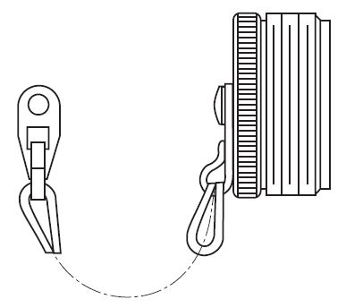
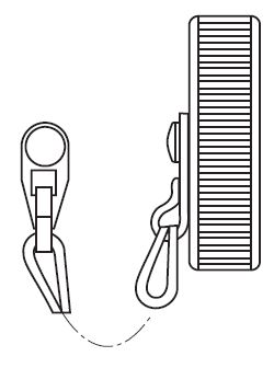
POLYCHLOROPRENE gaskets are used to insure a moisture-tight seal between a receptacle and the panel. Gaskets are available for front or rear panel mounting of STYLE 0, 2 and 9 connectors. Gasket thickness is approximately .037” (1.0 mm). Front Mounting Rear Mounting Shell Size Non-Conductive Conductive Non-Conductive Conductive 10S, 10SL MS52000-2 075-8512-001 075-8501-000 075-8501-001 12S, 12 MS52000-3 075-8513-001 075-8502-000 075-8502-001 14S, 14 MS52000-4 075-8514-001 075-8503-000 075-8503-001 16S MS52000-5 075-8515-001 075-8504-000 075-8504-001 16 MS52000-5 075-8515-001 075-8504-000 075-8504-001 18 MS52000-6 075-8516-001 075-8505-000 075-8505-001 20 MS52000-7 075-8517-001 075-8506-000 075-8506-001 22 MS52000-8 075-8518-001 075-8507-000 075-8507-001 24 MS52000-9 075-8519-001 075-8508-000 075-8508-001 28 MS52000-10 075-8520-001 075-8509-000 075-8509-001 32 MS52000-12 075-8521-001 075-8510-000 075-8510-001 36 MS52000-13 075-8522-001 075-8511-000 075-8511-001 DUST CAPSITT CANNON CT SERIES MIL-DTL-5015 CONNECTORS — METAL DUST CAPS WITH SASH CHAIN
Shell Size For Plug Styles 4 & 6 For Receptacle Styles 0, 1, 2, 7 & 9
10SL MS25042-10D* MS25043-10D* 12S MS25042-12D* MS25043-12D* 14S MS25042-14D* MS25043-14D* 16S MS25042-16D* MS25043-16D* 16 MS25042-16D* MS25043-16D* 18 MS25042-18D* MS25043-18D* 20 MS25042-20D* MS25043-20D* 22 MS25042-22D* MS25043-22D* 24 MS25042-24D* MS25043-24D* 28 MS25042-28D* MS25043-28D* 32 MS25042-32D* MS25043-32D* 36 MS25042-36D* MS25043-36D* * Select plating code A = Anodized Omit for chromate over cadmium DUMMY RECEPTACLESITT CANNON CT SERIES MIL-DTL-5015 CONNECTORS — DUMMY RECEPTACLES
Dummy Receptacles are for front or rear panel mounting. CT/MS series have threaded ramps.
The center of the connector is closed. Dummy receptacles mount on the same centers and
have the same outside dimensions as a STYLE 2 receptacle. The material is aluminum alloy
and has an olive chromate over cadmium plating. A version with a clearance hole through the
middle of the connector is also available. Contact us for ordering information.
Shell Size CT/MS
10SL MS3105-10S 12S MS3105-12S 14S MS3105-14S 16S MS3105-16S 16 MS3105-16 18 MS3105-18 20 MS3105-20 22 MS3105-22 24 MS3105-24 28 MS3105-28 32 MS3105-32 36 MS3105-36 |
SOLDER CONTACTSITT CANNON CT SERIES MIL-DTL-5015 CONNECTORS — SOLDER CONTACTS ASSEMBLY
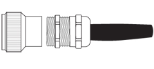
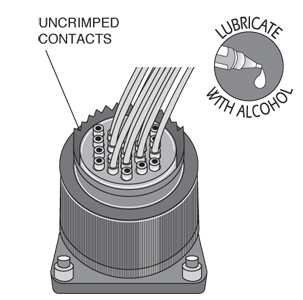
STEP 1: Slide the rear accessories over the wire bundle in the proper sequence for reassembly: cable clamp and/or endbell first, then ferrule and (if used) coupling nut. STEP 2: Insert individual wires through the proper holes in the grommet. Use isopropyl alcohol as a lubricant. STEP 3: Solder wires to appropriate contacts on the rear of the connector. ITT Cannon document RPI234 covers standard soldering practices and is available upon request by fax or mail. STEP 4: Fixture the connector for reassembly using endbell assembly tools. STEP 5: Slide the grommet down the wires (lubricating the grommet with isopropyl alcohol will help). STEP 6: Fill all unused grommet cavities with a wire hole filler to maintain the sealing integrity of the connector. STEP 7: Slide coupling nut, ferrule, and endbell accessories over rear of the connector and tighten. CRIMP TOOL OPERATIONITT CANNON CT SERIES MIL-DTL-5015 CONNECTORS — CRIMP TOOL OPERATION NOTE: Hand crimp tools can be used with size 16S, 16 & 12 contacts. Size 8, 4 and 0 contacts require the use of air powered crimp tools. Contact us for assistance in the use of these tools.
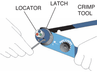
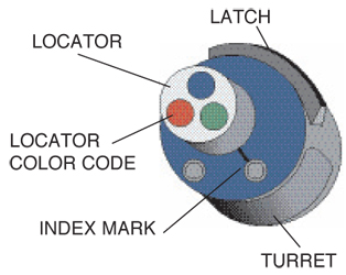
STEP 1: Strip the wires to the appropriate length. STEP 2: Open the AF8 crimp tool by squeezing the handles. Push the latch on the turret to pop up the locator. Attach the turret to the crimp tool using the two captive hex bolts in the turret. STEP 3: Select the proper locator position for your contact by rotating the locator until the proper color is aligned with the index mark. Push locator back down until it snaps into position. TH70-1 Contact Size Pin Locator Color Socket Locator Color 16S Blue Red 16 Red Green 12 TP567 TP567
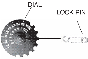
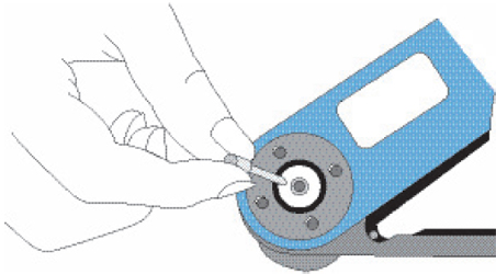
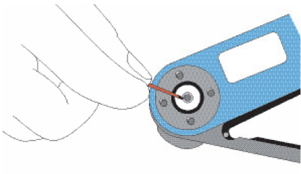
STEP 4: Adjust dial for proper wire gauge. To change the dial setting, remove the lock pin and lift center of dial. Turn to the desired wire gauge. Replace lock pin on dial. STEP 5: Cycle the tool before inserting the contact to be sure the tool is in the open position. Drop the contact, mating end first, into the crimp cavity of the tool. Squeeze the tool handle just enough to grip the contact without actually crimping it. STEP 6: Insert the stripped wire into the contact with a slight twisting motion. Be sure all wire strands are inside the contact. Squeeze the handle to cycle the tool. The handle will not release until the contact is completely crimped.
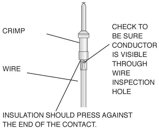
STEP 7: Remove the crimped contact. Pull on the wire slightly to be sure it is properly crimped. Be sure the contact is not bent or damaged in any way. Visually inspect the crimp. MICRO SECTIONS Enlargement of microsection allows for final judgement of crimp quality. This test is recommended whenever new tools or new types of wire or contacts are used. CONTACT INSERTIONITT CANNON CT SERIES MIL-DTL-5015 CONNECTORS — INSERTION OF CONTACTS
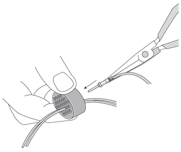
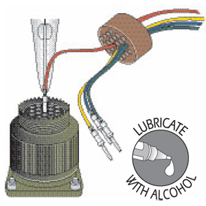
STEP 1: Slide the rear accessories over the wire bundle in the proper sequence for reassembly: cable clamp and/or endbell first, then ferrule, and coupling nut. STEP 2: Use the proper insertion tool. Place the contact in the tool. The tool should butt against the shoulder of the contact. Contact sizes 16S, 16, and 12 use a pliers style tool. Contact sizes 8, 4 and 0 use a tool with a ‘C’ shaped shaft. STEP 3: Lubricate the grommet with isopropyl alcohol (do not use any lubricant other than isopropyl alcohol). Insert the contact through the appropriate cavity in the grommet. Sizes 16S, 16 and 12 SOCKET contacts must be installed using guide pins.
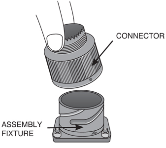
STEP 4: Place the connector into an assembly fixture (fixtures are available for production use, contact us.) If you are not using a fixture, be sure to allow clearance on the mating face of the connector for the guide pins to come through the connector during insertion. STEP 5: Lubricate the contact cavities of the connector insulator with isopropyl alcohol (do not use any other type of lubricant). STEP 6: Using guide pins where necessary, push straight down with a firm even pressure until the contact snaps into position in the proper cavity. Start at the center of the pattern and work toward the outer edges.
STEP 7: Fill any unused cavities with contacts. STEP 8: Check the mating face of the connector to insure that all the same size contacts are on the same plane (fully inserted). If not, the contact is not fully inserted. Remove the contact using the proper extraction tool and procedure and reinsert. Do not attempt to reinsert the insertion tool to correct the problem. STEP 9: A wire hole filler must be inserted into the grommet behind the unused contacts to maintain the sealing integrity of the connector. STEP 10: Place the connector back in the fixture for reassembly. Slide the connector accessories back down the cable over the rear of the connector and tighten. CONTACT EXTRACTIONITT CANNON CT SERIES MIL-DTL-5015 CONNECTORS — EXTRACTION OF CONTACTS
STEP 1: Remove the endbell accessories and slide them back over the wires. STEP 2: Use the proper extraction tool. The extraction tool can be used for both pin and socket contacts by removing the shaft from the handle and reversing it for pin or socket extraction. STEP 3: On the mating face of the connector, insert the tool over the pin contact or into the socket contact until the tool bottoms. Apply a slow continuous pressure to push the contact out the rear of the connector. When the shoulder of the tool “thunks” against the insulator, the contact is extracted. STEP 4: Carefully remove the extraction tool from the connector to avoid damage to the insulator. |
Philadelphia
19116
Click here for the contact information of the branch nearest you.


