ITT Cannon Trident Connectors: Trident Ringlock, Trident Neptune & TNM
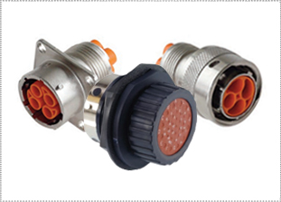
STRONG, LIGHTWEIGHT & LOW-COST
ITT Cannon Trident connectors are a family of cost-effective, reliable circular connectors that include the Trident Ringlock, Trident Neptune and TNM series. All three series of ITT Cannon Trident connectors are fully-sealed to IP67. The Trident Ringlock and Trident Neptune series are UL94-V0 circular plastic connectors with a metal coupling nut and bayonet retention mechanisms, providing the cost and weight benefits of a plastic connector with the durability of a metal connector. For full details on the ITT Cannon Trident connector family, see the product specifications below.
|
FEATURESITT CANNON TRIDENT SERIES (TRIDENT RINGLOCK, TRIDENT NEPTUNE & TNM) FEATURES
MATERIALS & FINISHESITT CANNON TRIDENT SERIES (TRIDENT RINGLOCK, TRIDENT NEPTUNE & TNM) MATERIALS & FINISHES
Shell UL94V0 thermoplastic with nickel plated copper alloy coupling nut and bayonet lock ring
Contacts High reliability copper alloy available in two versions, stamped and formed, or machined
Plating Tin, gold flash, gold (1 micron), heavy gold (3 microns)
Seals Rubber, silicone
ELECTRICAL DATAITT CANNON TRIDENT SERIES (TRIDENT RINGLOCK, TRIDENT NEPTUNE & TNM) ELECTRICAL DATA
Operating Voltage Up to 250 Vac rms degree of pollution permitting per IEC664 (TNM 700-volt power version)
Test Voltage 2000 Vac rms test potential
Current Rating 30 Amps (Neptune Power contacts), 13 Amps (Signal contacts). 16 Amp contacts available. New TNM 40 amp power.
Wire Range Sizes 28 - 14 AWG (stamped contacts), 28 - 16 AWG (machined), 18 -12 AWG (Power Neptune) 16-8 AWG (Power TNM)
Contact Resistance 5 Milliohms Initial
Insulation Resistance 5000 Megaohms at 500Vdc
Crimp Contacts Semi-automatic, hand-crimpable or fully-automatic
Wire Size 20 - 16 AWG
Wire Insulation Sealing Range 1.98 mm (.078 in) to 3.30 mm (.130 in) diameter
Contact Insertion No tool required. Suitable for automation
Contact Extraction Rear removable
Contact Retention 20 lbs. minimum per contact
Wire Strip Length 5.59 mm (.220 in) to 5.33 mm (.210 in)
MECHANICALITT CANNON TRIDENT SERIES (TRIDENT RINGLOCK, TRIDENT NEPTUNE & TNM) MECHANICAL
Operating Temperature -55° to +120ºC (-67º to +248ºF). 105°C maximum when 4 or more contacts are run near their maximum current. 105°C maximum when using tin contacts.
Sealing Up to IP67
Wire Sealing Range See column 9 on contact selection chart
Insulation Strip Length See column 8 on contact selection chart
Mating Life 500 cycles (machined contacts) 200 cycles (stamped)
Salt Spray To MIL-STD-1344 Method 1001 (48 hrs. no corrosion)
Heat Damp Heat to BS 2011 Pt2 Ca, 21 days exposure +105°C to -50°C (5 cycles) remains within specifications
Chemical Resistance Connectors show no damage when exposed to fluids used in industrial/vehicle applications.
Vibration 5 to 55 Hz (1 minute) No discontinuities longer than 1-microsecond
Shock 50g 11ms MIL-STD-202 Method 213 condition A
Contact Type Crimp, PC, first make/last break, co-ax, wire wrap
Number of Circuits 4 to 48.
Contact Insertion From rear. No insertion tool needed. Removable with proper extraction tool (front release).
Contact Retention: Force (Min.) Contact Lbs. Newtons Machined 25 110 Stamped 15 65 Polarization Standard or reversed sex shells and/or keying pins
Agency Listing UL (E102053), CSA (LR68300), TNM: UL, C-UL, E151413
Color Silver (TNM) or Black with silver coupling nut and ring (Ringlock and Neptune)
EXPLODED VIEWITT CANNON TRIDENT SERIES (TRIDENT RINGLOCK, TRIDENT NEPTUNE & TNM) EXPLODED VIEW
Neptune Plug Flanged Receptacle Jam Nut Receptacle Ringlock Plug Flanged Receptacle TNM Plug Flanged Receptacle CURRENT RATINGITT CANNON TRIDENT SERIES (TRIDENT RINGLOCK, TRIDENT NEPTUNE & TNM) CURRENT RATING (BY AMBIENT TEMPERATURE)
Curves apply to single contacts in isolation. Use of smaller wire gauges or more than one contact in a connector requires derating. HOW TO SELECT ITT CANNON TRIDENT SERIES (TRIDENT RINGLOCK, TRIDENT NEPTUNE & TNM) CONNECTORS
STEP 1. Determine number of circuits required per connector (4 to 48). Note that some Neptune layouts (shaded rows) have a mixture of power and signal contacts. STEP 2. Choose Trident Ringlock (waterjet proof) or Neptune (submersible). Neptune part numbers are shaded in chart. STEP 3. Select connector sex: STANDARD or REVERSED. Standard plugs have pin contacts, receptacles have sockets. Reversed plugs have socket contacts, receptacles have pins. STEP 4. Choose shell style: PLUG, FLANGED RECEPTACLE, or JAM NUT. STEP 5. Find part number on chart (remember, shaded part numbers are NEPTUNE). STEP 6. Select endbell, if needed. Neptune comes with low profile wire seal endbell; however, all endbells shown can be optionally used with Neptune connectors. STEP 7. Choose dust cap, if required. STEP 8. Select contacts and tooling below. HOW TO SELECT ITT CANNON TRIDENT SERIES (TRIDENT RINGLOCK, TRIDENT NEPTUNE & TNM) CONTACTS
STEP 1. Choose stamped or machined contacts. STEP 2. Choose contact type: crimp, PC, Power, first make/last break. STEP 3. Find your desired wire gauge in COLUMN 2. STEP 4. Choose contact plating in COLUMN 3. STEP 5. Select part number from COLUMNS 4, 5, 6, or 7. STEP 6. Select wire hole filler plugs (if needed) from COLUMN 10. Hole filler plugs are for Neptune version only (gray shaded connectors). Hole fillers are only used to re-seal unused grommet cavities that were punched out, but will not be filled with a wire. STEP 7. Select Keying pins (if needed) from COLUMN 11. STEP 8. Choose proper crimp tool for your contact from COLUMNS 12 thru 14. STEP 9. Choose proper extraction tool from COLUMN 15 (insertion tool not needed). STEP 10. Wire strip lengths and insulation dimensions are in COLUMNS 8 and 9. TNM CONNECTORSITT CANNON TRIDENT SERIES TNM CONNECTORS
The TNM range of connectors is an extension of the long established Neptune and Trident Ringlock connector series but with the advantage of a number of additional features. These include RF shielding and moisture sealing to IP67.
Power Contact TNM 700 Volts Only Type Sockets Pins Amp Max. Solder DM53744-21 DM53745-28 40 Crimp 8-10Awg DM130341-21 DM130338-28 40 Crimp 12-14Awg DM130342-21 DM130339-28 20 Crimp 16-18Awg DM130343-21 DM130340-28 10 |
|
ITT CANNON TRIDENT SERIES (TRIDENT RINGLOCK, TRIDENT NEPTUNE & TNM) APPLICATIONS
|
ITT CANNON TRIDENT SERIES TNM SELECT PART NUMBER
Standard Sex Reverse Sex Number of Contacts Shell Size Plug (pins) Flanged Receptacle (sockets) Plug (sockets) Flanged Receptacles (pins) Wire Sealing Range for Sealed Versions [inches(mm)] Gaskets Standard Plastic Unsealed Endbell 4 10 192993-0011 192993-0031 192993-0051 192993-0071 .055 (1.4) - 075-8543-011 192900-0639 † 4 10 192993-0001 192993-0021 192993-0041 192993-0061 No Wire Seal 075-8543-011 192900-0639 8 12 192993-0012 192993-0032 192993-0052 192993-0072 .055 (1.4) - 075-8543-012 192900-0640 † 8 12 192993-0002 192993-0022 192993-0042 192993-0062 No Wire Seal 075-8543-012 192900-0640 12 14 192993-0013 192993-0033 192993-0053 192993-0073 .055 (1.4) - 192900-0565 192900-0286 † 12 14 192993-0003 192993-0023 192993-0043 192993-0063 No Wire Seal 192900-0565 192900-0286 19 16 192993-0014 192993-0034 192993-0054 192993-0074 .055 (1.4) - 192900-0566 192900-0343 † 19 16 192993-0004 192993-0024 192993-0044 192993-0064 No Wire Seal 192900-0566 192900-0343 † Without wire seal but waterproof to IP67 when used with waterproof endbell.
Number of Contacts Shell Size Plastic Waterproof Gland Seal Endbell Cable Jacket Sealing Range for Plastic Endbell inches (mm) Shielded Metal Waterproof Gland Seal Endbell Cable Jacket Sealing Range for Metal Shielded Endbell Receptacle Metal Dust Cap Receptacle Plastic Dust Cap Metal Plug Dust Cap 4 † 4 10 10 192900-0636 192900-0636 .165(4.2)- .165(4.2)-
.173(4.4)- 192922-1480 192922-1480 192900-0376 192900-0376 MS3180-10CA MS3180-10CA 8 † 8 12 12 192900-0637 192900-0637 .224(5.7)- .224(5.7)-
.252(6.4)- 192922-1490 192922-1490 192900-0377 192900-0377 MS3180-12CA MS3180-12CA 12 † 12 14 14 192900-0496 192900-0496 .256(6.5)- .256(6.5)-
.272(6.9)- 192922-1500 192922-1500 192900-0378 192900-0378 MS3180-14CA MS3180-14CA 19 † 19 16 16 192900-0497 192900-0497 .256(6.5)- .256(6.5)-
.311(7.9)- 192922-1510 192922-1510 192900-0379 192900-0379 MS3180-16CA MS3180-16CA
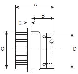
Shell Size Part Number A B C D E (Std.) E (Rev.) 10 192993-0081 2.228 (56.6) .315 (8.0) .705 (17.9) .512 (13.0) 3.484 (88.5) 3.150 (80.0) 12 192993-0082 2.232 (56.7) .394 (10.0) .827 (21.0) .630 (16.0) 3.484 (88.5) 3.150 (80.0) 14 192993-0083 2.244 (57.0) .449 (11.3) .945 (24.0) .748 (19.0) 3.484 (88.5) 3.150 (80.0) 16 192993-0084 2.260 (57.4) .535 (13.6) 1.079 (27.4) .866 (22.0) 3.484 (88.5) 3.150 (80.0) ITT CANNON TRIDENT SERIES (TRIDENT RINGLOCK, TRIDENT NEPTUNE & TNM) CONNECTORS - STANDARD SEX
Index Connectors Neptune (Shaded) Ringlock
Standard Sex Layouts Total Number of Circuits Number of Number of Shell Size Plug Plug (Pins) Flanged Jam Nut
192900-0469 192991-0628 (L) 192900-0539 192991-0660 (L) 192900-0475 192991-0640 (L) 192900-0481 192991-0644 (L) Mating face of plug for Standard Sex is shown. Reverse Sex have mirror image cavity identification. +2 COAX / Power +12 signal Ringlock version contact us for details. Shaded Columns = Neptune Version - Supplied with individual wire seal. Read Less ITT CANNON TRIDENT SERIES (TRIDENT RINGLOCK, TRIDENT NEPTUNE & TNM) CONNECTORS - REVERSE SEX
Index Connectors Neptune (Shaded) Ringlock
Reverse Sex Layouts Total Number of Circuits Number of Number of Shell Size Plug Plug (Sockets) Plastic Coupling Flanged Receptacle (Pins) Jam Nut Receptacle (Pins)
192900-0425 192991-0648(L) 192900-0542 192991-0664(L) 192900-0431 192991-0652(L) 192900-0437 192991-0656(L) Shaded columns = Neptune Version - Supplied with individual wire seal. Read Less ITT CANNON TRIDENT SERIES (TRIDENT RINGLOCK, TRIDENT NEPTUNE & TNM) SEAL, GASKET & ENDBELLS
Index Seal Gasket Endbells
**For Jam Nut Ringlock Neptune
Layouts Number of Circuits Shell Size Min OD/Max OD
192990-
192990-
192990-
192990-
192990-
192990-
192990-
192990-
192900-0565*
192900-
Signal: .067(1.7)/.106(2.7) 192900-0566*
192991- 192900-
192990-
192990-
192900-0566*
192991- 192900-
192990-
192990-
Signal:.067(1.7)/.106(2.7) 192900-0567*
192991- 192900-
192990-
192990-
Signal: .067(1.7)/.106(2.7) 192900-0567*
192991- 192900-
Signal: .067(1.7)/.106(2.7) 192900-0567*
192991- 192900-
192990-
192990-
192990-
192990-
Signal: .063(1.6)/.087(2.2) 192900-0567* - 192991-0013 192900-0498 Shaded columns = Neptune Version - Supplied with individual wire seal Read Less ITT CANNON TRIDENT SERIES (TRIDENT RINGLOCK, TRIDENT NEPTUNE & TNM) ENDBELLS & DUSTCAPS
Index Endbells Dustcaps (Also Fits KPT/KPSE Series)
Layouts Number of Circuits Shell Size Receptacle Metal Receptacle Plastic Dust Cap Plug Plastic
∆ Large minimums may apply to these caps ‡ Plug cap can be panel mounted and used as a dummy receptacle. Contact us for instructions. Large minimums may apply to these caps Read Less |
|
TRIDENT CONTACTS & WIRE RANGEITT CANNON TRIDENT SERIES (TRIDENT RINGLOCK, TRIDENT NEPTUNE & TNM) - CONTACTS & WIRE RANGE
Contacts(1) Wire Range Trident A.W.G. Plating Loose 3K Loose 3K Reel Sockets Wire Strip Lengths-Inches (MM) Wire Insulation Diameter- Inches (MM) Stamped Crimp
24-26
14 Tin Tin Tin Tin 192990-0020 192990-0040 192990-0060 192990-1240 192990-2510 192990-2500 192990-2490 192990-2480 192990-0030 192990-0050 192990-0070 192990-1250 192990-2550 192990-2540 192990-2530 192990-2520
N/A Machined Crimp
Machined Solder for Prototyping 28-14 AWG wire Pin Socket Tin- Tin- Gold- Gold- 24-28 24 22 20 20 16-18 Gold flash Gold flash Gold flash Gold flash Gold flash Gold flash 192991-0099 192991-0091 192991-0095 192991-0127 192991-0087 192991-0083 192991-0036 192991-0037 192991-0038 192991-0039 192991-0040 192991-0041
First Make Last Break Machined Contacts
20 16 Tin Tin 192991-0166 192991-0162 192991-0211 192991-0212
Printed Circuit Board Contacts
PC post dia. .043(1.10) Tin 192991-0198 192991-0204
Power Stamped 30 Amp-200 insertions
16-18 Tin 031-8717-020 121668-0000 031-8717-120 121668-0100 .20 (5.0) .055-.079 (1.4-2.0) Co-ax Twisted Pair (used only in signal contact cavities) Outer Female Contact Assembly Twisted Pair (B)
192945-4530 192945-4930 Contact us data sheet containing wire preparation information, tooling, and cable types. (1) Loose or 3K Reel Stamped contacts are available loose piece or on continuous reels of 3,000 for use with semi-automated crimping systems. Contact us for information. TRIDENT ACCESSORIES & TOOLSITT CANNON TRIDENT SERIES (TRIDENT RINGLOCK, TRIDENT NEPTUNE & TNM) - ACCESSORIES & TOOLS
Accessories Tools
Trident Wire Hole Fillers Neptune Only(2) Keying Pins(3) NEW: See Automatic Crimp Tooling Economy Non-Ratcheting Hand Crimp Tool(5) Extraction Tool(6) Hand Crimp Tool(4)
192991-0018 192991-0018 192991-0018 192991-0018 192990-0000 192990-0000 192990-0000 192990-0000
(20-26 AWG) 121586-5237 121586-5238 192922-1440 192922-1440 192922-1440 - 192922-1450 192922-1450 192922-1450 192922-1450 Locator(4)
Machined Solder for Prototyping 28-14 AWG wire Pin Socket Tin- Tin- Gold- Gold- 192991-0018 192991-0018 192991-0018 192991-0018 192991-0018 192991-0018 192990-0000 192990-0000 192990-0000 192990-0000 192990-0000 192990-0000 AF8 AF8 AF8 AF8 AF8 AF8 TH499 TH499 TH499 TH499 TH499 TH499 - - - - - - 192922-1450 192922-1450 192922-1450 192922-1450 192922-1450 192922-1450 First Make Last Break Machined Crimp
192991-0018 192991-0018 192990-0000 192990-0000 AF8 AF8 TH499 TH499 - - 192922-1450 192922-1450 Printed Circuit Board Contacts
↑ - - - 192922-1450 Hand Crimp Tool(4)
192991-0019 192990-0189 112108-0012 192922-1440 192900-0176 Hand Crimp Tool(4) Locator(4) Outer Female Contact Assembly Contact us for data sheet containing wire preparation information, tooling and cable types.
(2) Wire Hole Fillers (Neptune only) The rear Neptune wire seal has individual wire seals that are punched out when inserting the contact. If a seal is accidentally pierced, the seal can be repaired by inserting a wire hole filler. (3) Keying Pins A plastic pin, which can be snapped into an unused signal or power contact hole. This will only allow another connector to mate if there is an empty hole opposite the keying pin. Used to polarize similar connectors to avoid mis-mating. (4) Hand Crimp Tool & Locator Hand crimp tools produce consistent, high quality crimps by using a ratchet mechanism which will only release the contact when the crimp is completed. Stamped contacts use a tool with integrated dies. Machined contacts use a military style tool (MIL-C-22520/1) which also requires the appropriate locator to form a complete crimping system. (5) Economy Crimp Tool (stamp contacts only) This is a pliers style tool for prototype or service use. It has no ratchet and the completed crimp requires two separate operations, one to crimp the conductor, and a second crimp to secure the insulation support. The economy tool covers wire gauges 16, 20, and 24 AWG and is for use with stamped contacts only. (6) Extraction Tool Contacts can be easily removed by placing the extraction tool over the contact in the front of the connector and pushing. The contact is ejected from the rear of the connector. No insertion tool is needed for any Trident contacts. |
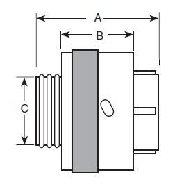
TNMITT CANNON TRIDENT SERIES TNM STANDARD PLUG
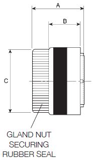
Number of Contacts Shell Size Part A B C D 4 10 192993-0011 1.673 (42.5) .580 (14.7) .689 (17.5) .850 (21.6) † 4 10 192993-0001 1.500 (38.1) .580 (14.7) .543 (13.8) .850 (21.6) 8 12 192993-0012 1.673 (42.5) .580 (14.7) .811 (20.6) .976 (24.8) † 8 12 192993-0002 1.500 (38.1) .580 (14.7) .665 (16.9) .976 (24.8) 12 14 192993-0013 1.673 (42.5) .580 (14.7) .957 (24.3) 1.102 (28.0) † 12 14 192993-0003 1.500 (38.1) .580 (14.7) .791 (20.1) 1.102 (28.0) 19 16 192993-0014 1.673 (42.5) .580 (14.7) 1.063 (27.0) 1.229 (31.2) † 19 16 192993-0004 1.500 (38.1) .580 (14.7) .917 (23.3) 1.229 (31.2) † Dimensions without wire seal and standard wire seal endbell. ITT CANNON TRIDENT SERIES TNM STANDARD FLANGED RECEPTACLES
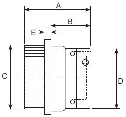
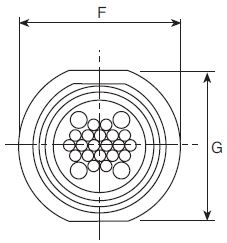
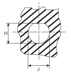
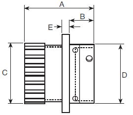
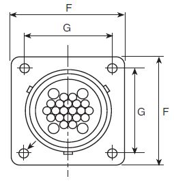
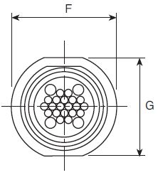
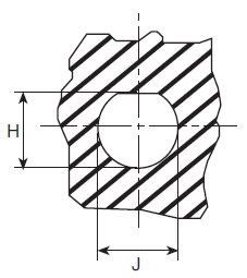
Number of Contacts Shell Size Part A C D F G H J K 4 10 192993-0031 1.366 (34.7) .689 (17.5) .587 (14.92) .937 (23.79) .719 (18.26) .126 (3.2) .594 (15.1) .681 (17.3) † 4 10 192993-0021 1.193 (30.3) .563 (14.3) .587 (14.92) .937 (23.79) .719 (18.26) .126 (3.2) .594 (15.1) .681 (17.3) 8 12 192993-0032 1.366 (34.7) .811 (20.6) .747 (18.98) 1.030 (26.15) .812 (20.62) .126 (3.2) .717 (18.2) .858 (21.8) † 8 12 192993-0022 1.193 (30.3) .685 (17.4) .747 (18.98) 1.030 (26.15) .812 (20.62) .126 (3.2) .717 (18.2) .858 (21.8) 12 14 192993-0033 1.366 (34.7) .957 (24.3) .872 (22.16) 1.124 (28.54) .898 (22.80) .138 (3.5) .843 (21.4) .984 (25.0) † 12 14 192993-0023 1.193 (30.3) .811 (20.6) .872 (22.16) 1.124 (28.54) .898 (22.80) .138 (3.5) .843 (21.4) .984 (25.0) 19 16 192993-0034 1.366 (34.7) 1.063 (27.0) .997 (25.33) 1.216 (30.89) .969 (24.61) .138 (3.5) .969 (24.6) 1.106 (28.1) † 19 16 192993-0024 1.193 (30.3) .937 (23.8) .997 (25.33) 1.216 (30.89) .969 (24.61) .138 (3.5) .969 (24.6) 1.106 (28.1) † Dimensions without wire seal and standard wire seal endbell. ITT CANNON TRIDENT SERIES TNM REVERSED PLUG
Number of Contacts Shell Size Part A B C D 4 10 192993-0051 1.346 (34.2) .580 (14.7) .689 (17.5) .850 (21.6) † 4 10 192993-0041 1.173 (29.8) .580 (14.7) .543 (13.8) .850 (21.6) 8 12 192993-0052 1.346 (34.2) .580 (14.7) .811 (20.6) .976 (24.8) † 8 12 192993-0042 1.173 (29.8) .580 (14.7) .665 (16.9) .976 (24.8) 12 14 192993-0053 1.346 (34.2) .580 (14.7) .957 (24.3) 1.102 (28.0) † 12 14 192993-0043 1.173 (29.8) .580 (14.7) .791 (20.1) 1.102 (28.0) 19 16 192993-0054 1.346 (34.2) .580 (14.7) 1.063 (27.0) 1.229 (31.2) † 19 16 192993-0044 1.173 (29.8) .580 (14.7) .917 (23.3) 1.229 (31.2) † Dimensions without wire seal and standard wire seal endbell. ITT CANNON TRIDENT SERIES TNM REVERSED FLANGED RECEPTACLES
Number of Contacts Shell Size Part A C D F G H J K 4 10 192993-0071 1.693 (43.0) .689 (17.5) .587 (14.92) .937 (23.79) .719 (18.26) .126 (3.2) .594 (15.1) .681 (17.3) † 4 10 192993-0061 1.520 (38.6) .563 (14.3) .587 (14.92) .937 (23.79) .719 (18.26) .126 (3.2) .594 (15.1) .681 (17.3) 8 12 192993-0072 1.693 (43.0) .811 (20.6) .747 (18.98) 1.030 (26.15) .812 (20.62) .126 (3.2) .717 (18.2) .858 (21.8) † 8 12 192993-0062 1.520 (38.6) .685 (17.4) .747 (18.98) 1.030 (26.15) .812 (20.62) .126 (3.2) .717 (18.2) .858 (21.8) 12 14 192993-0073 1.693 (43.0) .957 (24.3) .872 (22.16) 1.124 (28.54) .898 (22.80) .138 (3.5) .843 (21.4) .984 (25.0) † 12 14 192993-0063 1.520 (38.6) .811 (20.6) .872 (22.16) 1.124 (28.54) .898 (22.80) .138 (3.5) .843 (21.4) .984 (25.0) 19 16 192993-0074 1.693 (43.0) 1.063 (27.0) .997 (25.33) 1.216 (30.89) .969 (24.61) .138 (3.5) .969 (24.6) 1.106 (28.1) † 19 16 192993-0064 1.520 (38.6) .937 (23.8) .997 (25.33) 1.216 (30.89) .969 (24.61) .138 (3.5) .969 (24.6) 1.106 (28.1) † Dimensions without wire seal and standard wire seal endbell. STANDARDITT CANNON TRIDENT SERIES (TRIDENT RINGLOCK & TRIDENT NEPTUNE) STANDARD PLUG
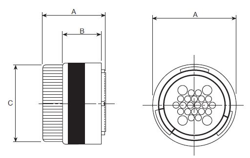
Ringlock Neptune Layout Shell Size Standard Plug A B C D 0-4 10 192922-1250 1.252 .756 .429 .850 0-7 18 192922-1330 1.299 .756 .885 1.350 0-8 12 192922-1260 1.252 .756 .543 .976 0-12 14 192922-1270 1.252 .756 .669 1.102 0-12 14 192900-0303 1.527 .756 .956 1.102 2-13 16 192900-0507 1.566 .751 1.063 1.189 0-19 16 192922-1280 1.252 .751 .783 1.228 0-19 16 192900-0017 1.566 .756 1.063 1.189 0-23 18 192990-1320 1.252 .756 .881 1.350 4-20 24 192900-0014 1.566 .580 1.594 1.732 0-28 20 192922-1290 1.252 .751 1.007 1.476 12-19 24 192900-0016 1.566 .756 1.594 1.732 4-28 24 192900-0015 1.566 .756 1.594 1.732 0-35 22 192922-1300 1.252 .580 1.122 1.602 0-48 24 192990-1340 1.252 .756 1.248 1.728 0-48 24 192900-0469 1.566 .756 1.594 1.732 0-48 (L) 24 192991-0628 2.000 .756 1.594 1.732 All dimensions are shown in inches. ITT CANNON TRIDENT SERIES (TRIDENT RINGLOCK & TRIDENT NEPTUNE) STANDARD FLANGED RECEPTACLE
Ringlock Neptune Layout Shell Size Standard Flanged Receptacle A B C D E F G H J K 0-4 10 192990-1660 1.016 .439 .433 .591 .091 .925 .709 .128 .594 .681 0-7 8 192990-1700 1.280 .716 .886 1.122 .098 1.311 1.063 .128 1.094 1.232 0-8 12 192990-1670 1.016 .447 .547 .758 .091 1.031 .807 .128 .717 .858 0-12 14 192990-1680 1.016 .447 .673 .874 .091 1.108 .890 .128 .842 .984 0-12 14 192900-0308 1.563 .448 .956 .874 .091 1.122 .901 .126 .968 .968 2-13 16 192900-0509 1.566 .448 1.063 1.000 .091 1.220 .964 .126 1.106 1.106 0-19 16 192990-1690 1.016 .447 0.787 1.000 .091 1.200 .953 .128 .968 1.106 0-19 16 192900-0039 1.566 .448 1.063 1.000 .091 1.220 .964 .126 1.106 1.106 0-23 18 192990-1710 1.016 .447 .886 1.122 .098 1.311 1.059 .128 1.094 1.232 4-20 24 192900-0030 1.645 .606 1.578 1.500 .138 2.000 1.563 .165 1.614 1.614 0-28 20 192990-1720 1.311 .571 1.012 1.248 .098 1.437 1.150 .128 1.216 1.358 12-19 24 192900-0036 1.645 .606 1.578 1.500 .138 2.000 1.563 .165 1.614 1.614 4-28 24 192900-0033 1.645 .606 1.578 1.500 .138 2.000 1.563 .165 1.614 1.614 0-35 22 192990-1730 1.311 .571 1.126 1.374 .138 1.563 1.244 .128 1.342 1.484 0-48 24 192990-1740 1.311 .602 1.252 1.500 .138 1.689 1.356 .154 1.468 1.610 0-48 24 192900-0475 1.645 .606 1.578 1.500 .138 2.000 1.563 .165 1.614 1.614 0-48 (L) 24 192991-0640 2.075 .606 1.578 1.500 .138 2.000 1.563 .165 1.614 1.614 All dimensions are shown in inches. ITT CANNON TRIDENT SERIES (TRIDENT NEPTUNE) STANDARD JAM NUT RECEPTACLE
Neptune only
Layout Shell Size Standard Jam Nut Receptacle A B C D E F G H J 0-12 14 192900-0313 1.563 .870 .956 .874 .138 1.410 1.267 .988 1.075 0-19 16 192900-0490 1.565 .905 1.063 1.000 .090 1.566 1.511 1.102 1.200 2-13 16 192900-0508 1.565 .905 1.063 1.000 .090 1.566 1.511 1.102 1.200 4-20 24 192900-0032 1.646 .921 1.579 1.500 .138 2.008 1.870 1.634 1.701 12-19 24 192900-0038 1.646 .921 1.579 1.500 .138 2.008 1.870 1.634 1.701 4-28 24 192900-0035 1.646 .921 1.579 1.500 .138 2.008 1.870 1.634 1.701 0-48 (L) 24 192991-0644 2.075 .921 1.579 1.500 .138 2.008 1.870 1.634 1.701 0-48 24 192900-0481 1.646 .921 1.579 1.500 .138 2.008 1.870 1.634 1.701 All dimensions are shown in inches. REVERSEITT CANNON TRIDENT SERIES (TRIDENT RINGLOCK & TRIDENT NEPTUNE) REVERSE PLUG
Ringlock Neptune Layout Shell Size Reverse Plug A B C D 0-4 10 192926-0500 1.027 .752 .433 .850 0-8 12 192926-0510 1.008 .752 .547 .976 0-12 14 192926-0520 1.055 .752 .673 1.102 0-12 14 192900-0236 1.244 .752 .957 1.102 0-19 16 192926-0530 1.087 .752 .787 1.228 0-19 16 192900-0057 1.248 .752 1.063 1.189 2-13 16 192900-0581 1.248 .752 1.063 1.189 0-7 18 192990-1390 1.240 .752 .885 1.350 0-23 18 192990-1380 1.008 .752 .885 1.350 0-28 20 192926-0540 1.232 .752 1.011 1.476 0-35 22 192926-0550 1.232 .752 1.126 1.602 4-20 24 192900-0054 1.275 .580 1.594 1.732 12-19 24 192900-0056 1.275 .580 1.594 1.732 4-28 24 192900-0055 1.275 .580 1.594 1.732 0-48 (L) 24 192991-0648 1.693 .580 1.594 1.732 0-48 24 192900-0425 1.275 .580 1.594 1.732 0-48 24 192990-1400 1.232 .580 1.225 1.728 All dimensions are shown in inches ITT CANNON TRIDENT SERIES (TRIDENT RINGLOCK & TRIDENT NEPTUNE) REVERSE FLANGED RECEPTACLES
Ringlock
Neptune
Layout Shell Size Standard Flanged Receptacle A B C D E F G H J K 0-4 10 192990-1760 1.24 .447 .433 .591 .091 .925 .709 .128 .594 .681 0-7 18 192990-1800 1.346 .700 .886 1.122 .091 1.311 1.063 .128 1.094 1.232 0-8 12 192990-1770 1.240 .447 .547 .748 .091 1.031 .807 .128 .717 .858 0-12 14 192990-1780 1.240 .447 .673 .874 .091 1.108 .890 .128 .843 .984 0-12 14 192900-0256 1.563 .448 .956 .874 .090 1.122 .901 .126 .968 .968 2-13 16 192900-0582 1.566 .448 1.063 1.000 .090 1.220 .964 .126 1.106 1.106 0-19 16 192990-1790 1.240 .447 .787 1.000 .091 1.200 .953 .128 .969 1.106 0-19 16 192900-0078 1.566 .448 1.063 1.000 .090 1.220 .964 .126 1.106 1.106 0-23 18 192990-1810 1.240 .447 .886 1.122 .098 1.311 1.059 .128 1.094 1.232 4-20 24 192900-0069 1.646 .606 1.578 1.500 .137 2.000 1.563 .165 1.614 1.614 0-28 20 192990-1820 1.299 .573 1.012 1.248 .098 1.437 1.150 .128 1.217 1.358 12-19 24 192900-0075 1.646 .606 1.578 1.500 .137 2.000 1.563 .165 1.614 1.614 4-28 24 192900-0072 1.646 .606 1.578 1.500 .137 2.000 1.563 .165 1.614 1.614 0-35 22 192990-1830 1.299 .573 1.126 1.374 .138 1.563 1.244 .128 1.343 1.484 0-48 24 192990-1840 1.370 .604 1.252 1.498 .138 1.689 1.356 .154 1.469 1.610 0-48 24 192900-0431 1.646 .606 1.578 1.500 .137 2.000 1.563 .165 1.614 1.614 0-48 (L) 24 192991-0652 2.075 .606 1.578 1.500 .137 2.000 1.563 .165 1.614 1.614 All dimensions are shown in inches. ITT CANNON TRIDENT SERIES (TRIDENT NEPTUNE) REVERSE JAM NUT RECEPTACLE
Neptune Only
Layout Shell Size Reverse Jam Nut Receptacle A B C D E F G H J 0-12 14 192900-0266 1.563 .870 .956 .874 .137 1.409 1.267 .988 1.075 2-13 16 192900-0583 1.566 .905 1.063 1.000 .090 1.212 1.503 1.102 1.200 0-19 16 192900-0353 1.566 .905 1.063 1.000 .090 1.212 1.503 1.102 1.200 4-20 24 192900-0071 1.645 .921 1.578 1.500 .137 2.007 1.870 1.633 1.700 12-19 24 192900-0077 1.645 .921 1.578 1.500 .137 2.007 1.870 1.633 1.700 4-28 24 192900-0074 1.645 .921 1.578 1.500 .137 2.007 1.870 1.633 1.700 0-48 24 192900-0437 1.646 .921 1.578 1.500 .137 2.007 1.870 1.633 1.700 0-48 (L) 24 192991-0656 2.075 .921 1.578 1.500 .137 2.007 1.870 1.633 1.700 All dimensions are shown in inches. SEALED/UNSEALEDITT CANNON TRIDENT SERIES (TRIDENT RINGLOCK & TRIDENT NEPTUNE) SEALED CABLE CLAMPS FOR USE WITH JACKETED CABLES
Wire Sealing Diameter Shell Size Part # A Max B Max C+ .007 (.20) D Max Max. Min. Rear Thread 10 192990-1530 2.165 (55.0) .437 (11.1) .740 (18.8) 3.011 (76.5) .354 (9.0) .165 (4.2) PG 9 12 192990-1540 2.283 (58.0) .535 (13.6) .818 (20.8) 3.063 (77.8) .366 (9.3) .224 (5.7) PG 14 192990-1550 2.559 .574 .897 3.366 .488 .256 PG 14 192900-0496 2.559 .574 .897 3.366 .488 .256 PG 16 192990-1560 2.716 .653 .972 3.535 .488 .256 PG 16 192900-0497 2.716 .653 .972 3.535 .488 .256 PG 18 192990-1570 2.874 .653 .897 3.661 .630 .256 PG 20 192990-1580 3.267 .870 1.252 4.232 .748 .362 PG 22 192990-1590 3.543 .870 1.252 4.507 .748 .362 PG 24 192990-1600 4.133 1.165 1.645 5.059 1.040 .670 PG 24 192900-0498 4.133 1.165 1.645 5.059 1.040 .670 PG ITT CANNON TRIDENT SERIES (TRIDENT RINGLOCK & TRIDENT NEPTUNE) UNSEALED CABLE CLAMPS - STRAIN RELIEF AND WIRE PROTECTION
Shell Size Part # A+ .005 (.15) B Max C+ .005 (.15) D Max E+ .005 (.15) F Max 10 192922-1310 1.570 (39.9) .846 (21.5) .251 (6.4) .342 (8.7) .826 (21.0) 2.413 (61.3) 12 192922-1320 1.574 (40.0) .980 (24.9) .251 (6.4) .503 (12.8) .944 (24.0) 2.413 (61.3) 14 192922-1330 1.811 (46.0) 1.063 (27.0) .251 (6.4) .543 (13.8) 1.063 (27.0) 2.641 (67.1) 14 192900-0343 1.811 (46.0) 1.063 (27.0) .251 (6.4) .543 (13.8) 1.063 (27.0) 2.641 (67.1) 16 192922-1340 1.811 (46.0) 1.185 (30.1) .251 (6.4) .669 (17.0) 1.189 (30.2) 2.641 (67.1) 16 192900-0343 1.811 (46.0) 1.185 (30.1) .251 (6.4) .669 (17.0) 1.189 (30.2) 2.641 (67.1) 18 192990-1510 1.968 (50.0) 1.259 (32.0) .275 (7.0) .783 (19.9) 1.307 (33.2) 2.787 (70.8) 20 192922-1350 2.165 (55.0) 1.350 (34.3) .275 (7.0) .826 (21.0) 1.433 (36.4) 3.122 (79.3) 22 192922-1360 2.362 (60.0) 1.460 (37.1) .322 (8.2) .905 (23.0) 1.559 (39.6) 3.358 (85.3) 24 192990-1520 2.559 (65.0) 1.645 (41.8) .322 (8.2) 1.063 (27.0) 1.685 (42.8) 3.574 (90.8) 24 192900-0344 2.559 (65.0) 1.645 (41.8) .322 (8.2) 1.102 (28.0) 1.673 (42.5) 3.574 (90.8) RINGLOCK ADAPTERSITT CANNON TRIDENT SERIES (TRIDENT RINGLOCK) ADAPTERS FOR HEAT SHRINK BOOTS OR SLEEVING
Dimensions (Max.) Shell Size Part Number A B C H Thread 10 192990-1430 .827 (21.0) .712 (18.1) .755 (19.2) 9/16-24UNEF-2B 12 192990-1440 .944 (24.0) .921 (23.4) .755 (19.2) 11/16-24UNEF-2B 14 192990-1450 1.063 (27.0) .952 (24.2) .755 (19.2) 13/16-20UNEF-2B 16 192990-1460 1.189 (30.2) 1.165 (29.6) .846 (21.5) 15/16-20UNEF-2B 18 192990-1470 1.311 (33.3) 1.248 (31.7) .846 (21.5) 1-1/16-18UNEF-2B 20 192990-1480 1.437 (36.5) 1.409 (35.8) .897 (22.8) 1-3/16-18UNEF-2B 22 192990-1490 1.563 (39.7) 1.503 (38.2) .897 (22.8) 1-5/16-18UNEF-2B 24 192990-1500 1.689 (42.9) 1.626 (41.3) .862 (21.9) 1-7/16-18UNEF-2B All dimensions in inches (millimeters in parentheses) unless otherwise stated. |
|
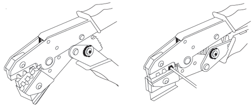
CRIMP TOOL OPERATIONThere are five different crimp tools used with Trident contacts. Find the appropriate tool on the Contact Selection Chart and follow the instructions for that tool below.ITT CANNON TRIDENT SERIES (TRIDENT RINGLOCK, TRIDENT NEPTUNE & TNM) HAND CRIMP TOOL FOR STAMPED CONTACTS
(192990-3140 for 16-28 AWG contacts and 192900-0175 for 14 AWG contacts)
STEP 1: Strip wires to length See strip length in Column 8 of contact chart STEP 2: Open the tool and select the proper crimp cavity for the wire gauge. STEP 3: Hold tool with the die cavity identification facing away from you. STEP 4: Pick up the contact by the mating end. Slip the contact into the appropriate die cavity so that the notch just behind the “gold” portion of the contact fits over the sliding plate on the lower half of the die. STEP 5: Squeeze the handle just enough to hold the contact in the die cavity. STEP 6: Turn the tool over and insert the stripped wire into the contact until it bottoms. STEP 7: Cycle the tool. The tool will not open until the contact has been completely crimped. STEP 8: Inspect the crimp. A contact crimp verification tool is available. Please contact us. ITT CANNON TRIDENT SERIES (TRIDENT RINGLOCK, TRIDENT NEPTUNE & TNM) CONTACT CRIMP TOOL
(121586-5236) (121586-5237) (121586-5238)
STEP 1: Strip wires to length see strip length in Column 8 of contact chart. STEP 2: Open the tool and select the proper crimp cavity for the wire gauge. STEP 3: Now hold the tool so that the cavity identification is away from you (the back side). STEP 4: Surrounding the lower die is a holding frame; push up on the tab to fully raise the frame. STEP 5: While holding the frame open, insert the power contact, wire side first, until the lip on the contact butts against the ledge of the lower die. The U shaped wire crimps should be upright in the die. STEP 6: Release the tab. The frame should now be holding the contact in the proper cavity, ready to crimp. STEP 7: Close the tool just enough to grip the contact. STEP 8: Insert the stripped wire into the contact from the wire side. STEP 9: Cycle the tool. The tool will not open until the contact has been completely crimped. An escape lever is located on the ratchet mechanism to release the tool if necessary. STEP 10: Inspect the crimp. See “Stamped Contacts” in Crimp Inspection section ITT CANNON TRIDENT SERIES (TRIDENT RINGLOCK, TRIDENT NEPTUNE & TNM) ECONOMY TOOL FOR STAMPED CONTACTS
(192922-1440)
STEP 1: Strip wires to length See strip length in Column 8 of contact chart. STEP 2: Select the proper crimp cavity for the wire gauge. STEP 3: The contact itself has two U shaped crimp areas, each requiring a separate crimp operation. The larger, rear U shape area crimps over the wire insulation and provides strain relief. The smaller, longer, U shape area crimps over the bare wire and provides the electrical connection. STEP 4: Insert the contact into the tool so that the smaller wire crimp u is upright and centered in the proper die (the open portion of the U facing the cavity identification on the tool). STEP 5: Close the tool just enough to grip the contact. STEP 6: Insert the stripped wire into the contact until it bottoms. STEP 7: Cycle the tool. STEP 8: Remove the crimped contact. now you must crimp the insulation grip. STEP 9: Place the insulation u upright in the die cavity marked INS. Crimp the Insulation U over the wire insulation in the same manner as the wire crimp. STEP 10: Inspect the two crimps. See “Stamped Contacts” in Crimp Inspection section. A contact crimp verification tool is available. Please contact us. ITT CANNON TRIDENT SERIES (TRIDENT RINGLOCK, TRIDENT NEPTUNE & TNM) CRIMP TOOL FOR MACHINED CONTACTS
(AF8 Tool and TH206 Turret)
STEP 1: Strip wires to length See strip length in Column 8 of contact chart. STEP 2: Open the crimp tool by squeezing the handles. Push the latch on turret to pop up the locator. Attach the turret to the crimp tool using the two captive hex bolts in the turret. STEP 3: Select the proper locator position for your contact by rotating the locator until the proper color is aligned with the index mark. Push locator back down until it snaps into position. Contact Type Locator Color Pins Blue Socket Green First-Mate Red STEP 4: Adjust dial for proper wire gauge. To change the dial setting, remove the lock pin and lift center of dial. Turn to the desired wire gauge. Replace lock pin on dial.
STEP 5: Cycle the tool before inserting the contact to be sure the tool is in the open position. Drop the contact, mating end first, into the crimp cavity of the tool. Squeeze the tool handle just enough to grip the contact without actually crimping it. STEP 6: Insert the stripped wire into the contact with a slight twisting motion. be sure all wire strands are inside the contact. Squeeze the handle to cycle the tool. The handle will not release until the contact is completely crimped. STEP 7: Remove the crimped contact. Pull on the wire slightly to be sure it is properly crimped. be sure the contact is not bent or damaged in any way. STEP 8: Visually inspect the crimp. See Machined Contacts drawing in Visual Check section on next page. ITT CANNON TRIDENT SERIES (TRIDENT RINGLOCK, TRIDENT NEPTUNE & TNM) AUTOMATIC CRIMP TOOLS FOR REELED STAMPED CONTACTS
Mini Applicator modules are used in industry-standard crimp presses. This allows for fast change-over for crimping different contacts. Using the same crimp press saves valuable factory floor space over multiple presses.
Mini Applicator Part Number Contact Type Metcal Schafer 20-26 Signal 121586-5239 121586-5142 16-18 Signal 121586-5217 121586-5141 14-16 Signal 121586-5240 Contact us for details Contact Type Mini Applicator Part Number 16-18 Power 193800-0031 14-16 Power 193800-0023 12-14 Power 193800-0023 ITT CANNON TRIDENT SERIES (TRIDENT RINGLOCK, TRIDENT NEPTUNE & TNM) ASSEMBLY INSPECTION
CRIMP INSPECTION (MICRO SECTIONS)
Enlargement of micro section allows for final judgment of crimp quality. This test is recommended whenever new tools or new types of wire are used. For Stamped Contacts
For Machined Contacts
INSERTION OF CONTACTSITT CANNON TRIDENT SERIES (TRIDENT RINGLOCK, TRIDENT NEPTUNE & TNM) INSERTION OF CONTACTS
No insertion tool is required.
STEP 1: Strip wires to length See strip length in Column 8 of contact chart. STEP 2: When using neptune connectors with the rear wire sealing grommet, put the grommet in place on the connector and push the contact directly through the grommet into the cavity. Start at the center of the layout and work concentrically to the outside edge to eliminate the possibility of the grommet shifting or bunching during loading. STEP 3: Inspect by looking at the mating side of the connector. be sure that all of the contacts are on the same plane (fully inserted). If not, use the extraction tool to remove the contact and re-insert. EXTRACTION OF CONTACTSITT CANNON TRIDENT SERIES (TRIDENT RINGLOCK, TRIDENT NEPTUNE & TNM) EXTRACTION OF CONTACTS
CRIMP TOOLS Contacts can be removed from the housings using the appropriate extraction tool. The tool is placed over the mating end of the contact and the sleeve is rotated slightly as it is pushed into the connector. IMPORTANT: Make sure the depth indicating line on the tool is even with the mating face of the connector before depressing the plunger to avoid damage to connector and contact. Light pressure on the plunger will eject the contact from the rear of the connector.
STEP 1: Contact in connector STEP 2: Extraction tool compresses tines STEP 3: Plunger pushes contact out rear of connector TRIDENT CONNECTORSITT CANNON TRIDENT SERIES TNM CONNECTOR ASSEMBLY INSTRUCTIONS STEP 1: Slide O ring over connector body and it will fit into a grove just past the accessory threading. STEP 2: Slide, clamp nut, cable clamp (Note: cable clamp compression fingers point toward the connector body), gland seal, (Use isopropyl alcohol to slide rubber gland), metal endbell body, metal shielding cone and, plastic retention clip in that order over your jacketed cable. STEP 3: Strip back cable jacket as shown. STEP 4: Terminate and insert contacts per assembly instructions. STEP 5: Slide plastic retention clip down onto the connector body. STEP 6: Pull braided cable shield over plastic retention clip. STEP 7: Slide metal shielding cone down until it snaps on to the plastic retention clip. The shield should now be captivated between plastic retention clip and metal shielding cone. STEP 8: Fold remaining braided cable shield back over the metal shielding cone. Step 9: Slide the metal endbell body down the cable and tighten by hand. STEP 10: Slide gland seal, cable clamp down into the back of the metal endbell. (Note: isopropyl alcohol will assist in sliding rubber gland seal on cable). STEP 11: Snug up endbell with appropriate wrench and endbell assembly tools. STEP 12: Push the cable grip up against the gland seal, then thread clamp nut onto endbell body and tighten to 10Nm+/-1Nm(88.50 inch/pounds). |
Philadelphia
19116
Click here for the contact information of the branch nearest you.


 Mates With


 Standard Strain Relief (unsealed)


