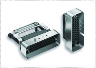
ITT Cannon Trident Multiway Rack & Panel Connectors

RECTANGULAR CONNECTORS RATED TO IP40
ITT Cannon Trident Multiway connectors are a family of cost-effective rectangular connectors tested to MIL-STD-202 and IEC 512, designed for exceptional performance in harsh environments. Trident Multiway Rack & Panel connectors have earned an International Ingress Protection (IP) rating of IP40, meaning they are completely sealed against dust and other solid objects and temporarily submersible up to 1m. ITT Cannon’s Rack & Panel interconnect solutions are manufactured to the highest quality and reliability standards for the aerospace and defense industry.
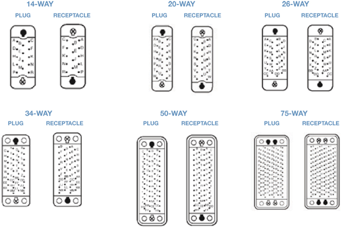
The Multiway range has six contact cavity arrangements available and offers an extremely reliable connector system, in which any Trident signal or coaxial contacts can be used.
All multi-rack & panel connectors are RoHS-compliant and recognized under the component program of CSA. For full details on the ITT Cannon Trident Multiway Rack & Panel rectangular connector series, please see the product specifications below.
|
FEATURESITT CANNON TRIDENT MULTIWAY RACK & PANEL CONNECTORS FEATURES
MATERIALS & FINISHESITT CANNON TRIDENT MULTIWAY CONNECTOR MATERIALS & FINISHES
Shell Anodized aluminum, zinc alloy, thermoplastic
Shell Plating Zinc alloy gray painted
Insulator Glass filled phenolic
Contact Copper-Alloy
Contact Plating Tin, Gold, Silver
Contact Style Crimp, solder
ELECTRICAL DATAITT CANNON TRIDENT MULTIWAY CONNECTOR ELECTRICAL DATA
Operating Voltage 250 V ac
Current Rating 16 A
Number of Signal Contacts (Min./Max.) 14 to 75
Gauge Wire Size Signal: AWG 26-14 (0.08 - 2.5 mm²)
MECHANICALITT CANNON TRIDENT MULTIWAY CONNECTOR MECHANICAL
Industry / MIL-SPEC # IEC 512, MIL-STD-202
Application/Market Industrial, Transportation
Shape Rectangular
Shell Style Plug and receptacle
Durability 500 mating cycles
Contact Style / Termination Crimp, Solder
TEST DATAITT CANNON TRIDENT MULTIWAY CONNECTOR TEST DATA Test Description IEC Test Military Standard Test Method Test Voltage 512-2 Test 4a MIL-STD-202 301 Insulation Resistance 512-2 Test 3a MIL-STD-202 302 Vibration 512-4 Test 6d MIL-STD-202 204, Condition A Shock 512-4 Test 6c MIL-STD-202 213 Humidity 512-6 Test 11c MIL-STD-202 103, Condition C Corrosion (Salt Spray) 512-6 Test 11f MIL-STD-202 101, Condition B Dry Heat 512-6 Test 11i MIL-STD-202 108A, Condition D PERFORMANCE DATAITT CANNON TRIDENT MULTIWAY CONNECTOR PERFORMANCE DATA
Temperature Range -55°C to +125°C (-67°F to +257°F) Plastic Hood assemblies limited to 105°C (221°F)
Test Voltage 200 V ac rms for 60 seconds
Insulation Resistance 5000MΩ min. at 500 V dc
Durability* Up to 500 Mating Cycles
Flamibility UL 94 V-0 (Insulators), UL 94 V-1 (Plastic Hoods)
Rated Current Dependent on choice of contact and application (usually limited by cable bundle factor)
* Up to 500 cycles for machined contacts; up to 200 cylces for stamped contacts |
|
ITT CANNON TRIDENT MULTIWAY CONNECTORS APPLICATIONS
|
|
ITT CANNON TRIDENT MULTIWAY CONNECTORS HOW TO ORDER
1 2 3 4 5 6 7 TM 50 P N 285 1 - SERIES PREFIX CONTACT ARRANGEMENT OR ACCESSORY CONTACT TYPE HARDWARE TYPE STYLE SELECTOR SERIES IDENTIFICATION SHROUD POLARIZATION CODE EXPLANATION SERIES PREFIX TM - Trident Multiway CONTACT ARRANGEMENT See Below CONTACT TYPE P - Plug HARDWARE STYLE N - Normal Hardware1 STYLE SELECTOR Plain, No Accessories SERIES IDENTIFICATION 1 - For all items in this product section SHROUD POLARIZING CODE Leave blank if not required. Contact us for other options. CONTACT CAVITY ARRANGEMENTS - MATING FACE VIEW
Note: |
|
ITT CANNON TRIDENT MULTIWAY CONNECTORS CONTACTS & TOOLING
Contacts (1) Column 1 Column 2 Column 3 Column 4 Column 5 Column 6 Column 7 Trident AWG Wire Size Plating Loose Pins 3K Reel Pin Loose Socket 3K Reel Sockets Stamped Crimp
Tin Tin Tin 192990-0020 192990-0040 192990-0060 192990-2510 192990-2500 192990-2490 192990-0030 192990-0050 192990-0070 192990-2550 192990-2540 192990-2530
Tin 192990-1240 192990-2480 192990-1250 192990-2520 Machined Crimp
Gold Flash Gold Flash Gold Flash Gold Flash Gold Flash Gold Flash 192991-0099 192991-0091 192991-0095 192991-0127 192991-0087 192991-0083 - - - - - - 192991-0036 192991-0037 192991-0038 192991-0039 192991-0040 192991-0041 - - - - - - Machined Solder for Prototyping
Tin Gold 192900-0632 192900-0633 - - 192900-0634 192900-0635 - - First Make/Last Break Machined Crimp
Tin Tin 192991-0166 192991-0162 - - 192991-0211 192991-0212 - - Printed Circuit Board Contacts
PC post dia.
Power Stamped 30 Amp - 200 insertions 16-18 Tin 031-8717-020 121668-0000 031-8717-120 121668-0100 Co-ax/Twisted Pair (Used only in signal contact cavities)
Wire Range Tools Column 1 Column 8 Column 9 Column 10 Column 11 Column 12 Column 13 Column 14 Trident Contacts Wire Strip Lengths Wire Insulation Diameter Keying Pins (2) Automatic Crimp Tooling Economy Non- Ratcheting Hand Crimp Tool(4) Extraction Tool (5) Hand Crimp Tool (3)
.035 - .0627 .046 - .081 .078 - .118 N/A No insulation grip 192990-0000 192990-0000 192990-0000 192990-0000 121586-5236 121586-5236 121586-5237 121586-5238
192922-1450 192922-1450 192922-1450 192922-1450 Locator (3)
.20 (5.0) .20 (5.0) .20 (5.0) .20 (5.0) .20 (5.0) .28 (7.1) .035 - .055 .041 - .062 .062 - .084 .051 - .070 .062 - .082 N/A No insulation grip 192990-0000 192990-0000 192990-0000 192990-0000 192990-0000 192990-0000 AF8 AF8 AF8 AF8 AF8 AF8 TH206 TH206 TH206 TH206 TH206 TH206 - - - - - - 192922-1450 192922-1450 192922-1450 192922-1450 192922-1450 192922-1450
.062 - .082 N/A No insulation grip 192990-0000 192990-0000 AF8 AF8 TH206 TH206 - - 192922-1450 192922-1450
Hand Crimp Tool (4) Locator (4)
Inner Conductor Outer Conductor
All dimensions shown in inches (millimeters in parentheses) (1) Loose or 3K Reel Stamped contacts are available loose piece or on continuous reels of 3,000 for use with semi-automated crimping systems. Contact us for information. (2) Keying Pins A plastic pin, which can be snapped into an unused signal or power contact hole. This will only allow another connector to mate if there is an empty hole opposite the keying pin. Used to polarize similar connectors to avoid mis-mating. (3) Hand Crimp Tool & Locator Hand crimp tools produce consistent, high quality crimps by using a ratchet mechanism which will only release the contact when the crimp is completed. Stamped contacts use a tool with integrated dies. Machined contacts use a military style tool (MIL-C-22520/1) which also requires the appropriate locator to form a complete crimping system. (4) Economy Crimp Tool (stamp contacts only) This is a pliers style tool for prototype or service use. It has no ratchet and the completed crimp requires two separate operations, one to crimp the conductor, and a second crimp to secure the insulation support. The economy tool covers wire gauges 16, 20, and 24 AWG and is for use with stamped contacts only. (5) Extraction Tool Contacts can be easily removed by placing the extraction tool over the contact in the front of the connector and pushing. The contact is ejected from the rear of the connector. No insertion tool is needed for any Trident contacts. |
|
ITT CANNON TRIDENT MULTIWAY CONNECTOR STYLE SELECTOR
PLAIN, NO ACCESSORIES
Rotating Jackscrews or fixed Jack Posts Guide Pins & Sockets No Shrouds 007 001 Shrouds 207 201 PLASTIC HOOD
Rotating Jackscrews or fixed Jack Posts Guide Pins & Sockets No Shrouds 155 (34-way only) 159 (14, 20,26 & 34- way only) Shrouds 255 (34-way only) 285 (14, 20,26 & 34- way only) DIE-CAST HOOD
Rotating Jackscrews or fixed Jack Posts Guide Pins & Sockets No Shrouds 157 (50 & 75-way only) 185 Shrouds 155 (50 & 75-way only) 285 STRAIGHT CABLE CLAMP
Rotating Jackscrews or fixed Jack Posts Guide Pins & Sockets No Shrouds 118 180 Shrouds 218 280 90 DEGREE CABLE CLAMP
Standard Cable Exit to Left Standard Cable Exit to Right Rotating Jackscrews or Guide Pins & Sockets Rotating Jackscrews or Guide Pins & Sockets No Shrouds 138 136 118 180 Shrouds 238 236 218 280 Note: Connectors with Jackscrews will not mate with connectors with Guide Pins or Sockets. Jackscrews available on 34-way only. |
|
CRIMP TOOL OPERATIONThere are five different crimp tools used with Trident contacts. Find the appropriate tool on the Contact Selection Chart and follow the instructions for that tool below.ITT CANNON TRIDENT MULTIWAY CONNECTOR HAND CRIMP TOOL FOR STAMPED CONTACTS
(192990-3140 for 16-28 AWG contacts and 192900-0175 for 14 AWG contacts)
STEP 1: Strip wires to length See strip length in Column 8 of contact chart STEP 2: Open the tool and select the proper crimp cavity for the wire gauge. STEP 3: Hold tool with the die cavity identification facing away from you. STEP 4: Pick up the contact by the mating end. Slip the contact into the appropriate die cavity so that the notch just behind the “gold” portion of the contact fits over the sliding plate on the lower half of the die. STEP 5: Squeeze the handle just enough to hold the contact in the die cavity. STEP 6: Turn the tool over and insert the stripped wire into the contact until it bottoms. STEP 7: Cycle the tool. The tool will not open until the contact has been completely crimped. STEP 8: Inspect the crimp. A contact crimp verification tool is available. Please Contact us for details. See “Stamped Contacts” in Crimp Inspection section. ITT CANNON TRIDENT MULTIWAY CONNECTOR CONTACT CRIMP TOOL
(121586-5236) (121586-5237) (121586-5238)
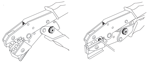
STEP 1: Strip wires to length see strip length in Column 8 of contact chart. STEP 2: Open the tool and select the proper crimp cavity for the wire gauge. STEP 3: Now hold the tool so that the cavity identification is away from you (the back side). STEP 4: Surrounding the lower die is a holding frame; push up on the tab to fully raise the frame. STEP 5: While holding the frame open, insert the power contact wire side first, until the lip of the contact hits against the ledge of the lower die. The u-shaped wire crimps should be upright in the die. STEP 6: Release the tab. The frame should now be holding the contact in the proper cavity, ready to crimp. STEP 7: Close the tool just enough to grip the contact. STEP 8: Insert the stripped wire into the contact from the wire side. STEP 9: Cycle the tool. The tool will not open until the contact has been completely crimped. An escape lever is located on the ratchet mechanism to release the tool if necessary. STEP 10: Inspect the crimp. See “Stamped Contacts” in Crimp Inspection section ITT CANNON TRIDENT MULTIWAY CONNECTOR ECONOMY TOOL FOR STAMPED CONTACTS
(192922-1440)
STEP 1: Strip wires to length See strip length in Column 8 of contact chart. STEP 2: Select the proper crimp cavity for the wire gauge. STEP 3: The contact itself has two u-shaped crimp areas, each requiring a separate crimp operation. The larger, rear u-shaped area crimps over the wire insulation and provides strain relief. The smaller, longer, u-shaped area crimps over the bare wire and provides the electrical connection. STEP 4: Insert the contact into the tool so that the smaller wire crimp u is upright and centered in the proper die (the open portion of the U facing the cavity identification on the tool). STEP 5: Close the tool just enough to grip the contact. STEP 6: Insert the stripped wire into the contact until it bottoms. STEP 7: Cycle the tool. STEP 8: Remove the crimped contact. now you must crimp the insulation grip. STEP 9: Place the insulation u upright in the die cavity marked INS. Crimp the Insulation U over the wire insulation in the same manner as the wire crimp. STEP 10: Inspect the two crimps. See “Stamped Contacts” in Crimp Inspection section. A contact crimp verification tool is available. Please contact us for details. ITT CANNON TRIDENT MULTIWAY CONNECTOR CRIMP TOOL FOR MACHINED CONTACTS
There are five different crimp tools used with Trident contacts. Find the appropriate tool on the Contact Selection Chart and follow the instructions for that tool below.
STEP 1: Strip wires to length See strip length in Column 8 of contact chart. STEP 2: Open the crimp tool by squeezing the handles. Push the latch on turret to pop up the locator. Attach the turret to the crimp tool using the two captive hex bolts in the turret. STEP 3: Select the proper locator position for your contact by rotating the locator until the proper color is aligned with the index mark. Push locator back down until it snaps into position. Contact Type Locator Color Pins Blue Socket Green First-Mate Red STEP 4: Adjust dial for proper wire gauge. To change the dial setting, remove the lock pin and lift center of dial. Turn to the desired wire gauge. Replace lock pin on dial.
STEP 5: Cycle the tool before inserting the contact to be sure the tool is in the open position. Drop the contact, mating end first, into the crimp cavity of the tool. Squeeze the tool handle just enough to grip the contact without actually crimping it. STEP 6: Insert the stripped wire into the contact with a slight twisting motion. Be sure all wire strands are inside the contact. Squeeze the handle to cycle the tool. The handle will not release until the contact is completely crimped. STEP 7: Remove the crimped contact. Pull on the wire slightly to be sure it is properly crimped. Be sure the contact is not bent or damaged in any way. STEP 8: Visually inspect the crimp. See Machined Contacts drawing in Visual Check section on next page. ITT CANNON TRIDENT MULTIWAY CONNECTOR AUTOMATIC CRIMP TOOLS FOR REELED STAMPED CONTACTS
Mini Applicator modules are used in industry-standard crimp presses. This allows for fast change-over for crimping different contacts. Using the same crimp press saves valuable factory floor space over multiple presses.
Mini Applicator Part Number Contact Type Metcal Schafer 20-26 Signal 121586-5239 121586-5142 16-18 Signal 121586-5217 121586-5141 14-16 Signal 121586-5240 Contact Type Mini Applicator Part Number 16-18 Power 193800-0031 14-16 Power 193800-0023 12-14 Power 193800-0023 ITT CANNON TRIDENT MULTIWAY CONNECTOR ASSEMBLY INSPECTION
CRIMP INSPECTION (MICRO SECTIONS)
Enlargement of micro section allows for final judgment of crimp quality. This test is recommended whenever new tools or new types of wire are used. For Stamped Contacts
For Machined Contacts
CONTACT INSERTIONITT CANNON TRIDENT MULTIWAY CONNECTOR CONTACT INSERTION
No insertion tool is required.
STEP 1: Strip wires to length See strip length in Column 8 of contact chart STEP 2: When using neptune connectors with the rear wire sealing grommet, put the grommet in place on the connector and push the contact directly through the grommet into the cavity. Start at the center of the layout and work concentrically to the outside edge to eliminate the possibility of the grommet shifting or bunching during loading. STEP 3: Inspect by looking at the mating side of the connector. Be sure that all of the contacts are on the same plane (fully inserted). If not, use the extraction tool to remove the contact and re-insert. CONTACT EXTRACTIONITT CANNON TRIDENT MULTIWAY CONNECTOR CONTACT EXTRACTION
CRIMP TOOLS Contacts can be removed from the housings using the appropriate extraction tool. The tool is placed over the mating end of the contact and the sleeve is rotated slightly as it is pushed into the connector. IMPORTANT: Make sure the depth indicating line on the tool is even with the mating face of the connector before depressing the plunger to avoid damage to connector and contact. Light pressure on the plunger will eject the contact from the rear of the connector.
STEP 1: Contact in connector STEP 2: Extraction tool compresses tines STEP 3: Plunger pushes contact out rear of connector |
Philadelphia
19116
Click here for the contact information of the branch nearest you.


