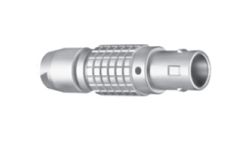
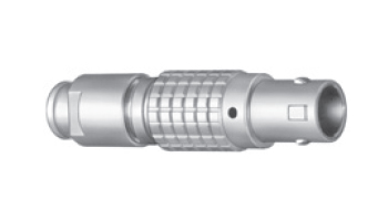
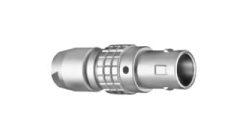
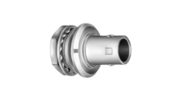
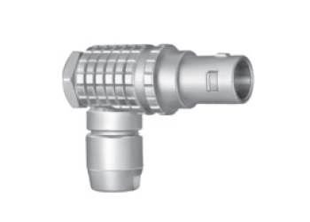
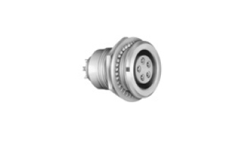
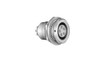
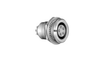
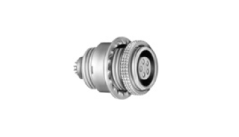
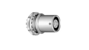
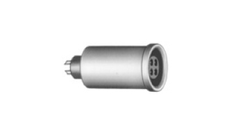
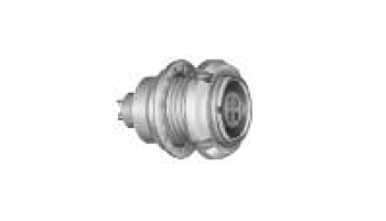
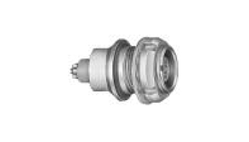
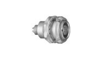
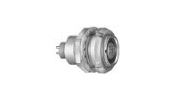
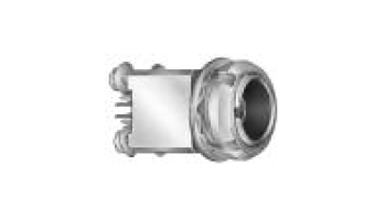
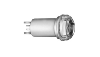
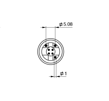
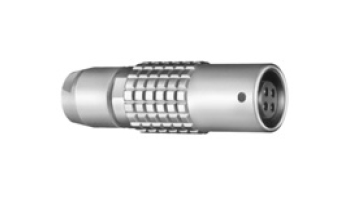
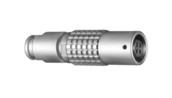
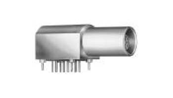
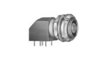
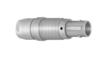
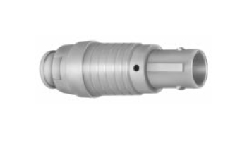
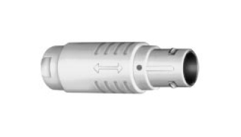
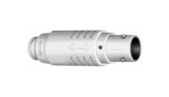
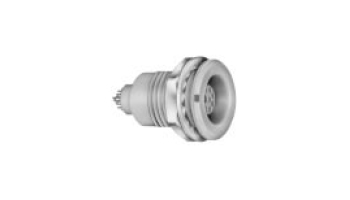
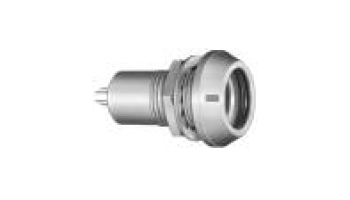
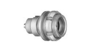
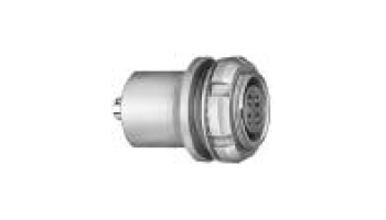
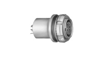
LEMO B Series Push Pull Connector
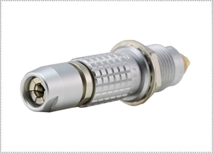
SECURE HIGH-DENSITY PUSH PULL CONNECTOR
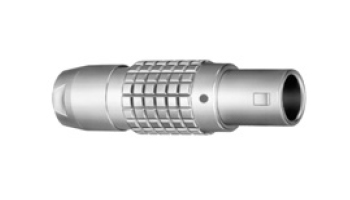
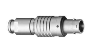
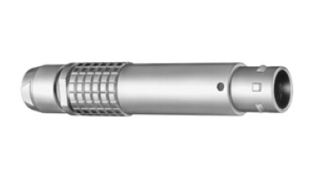
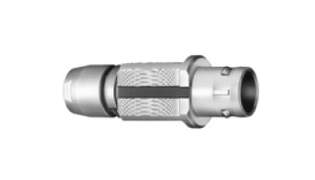
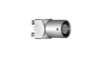
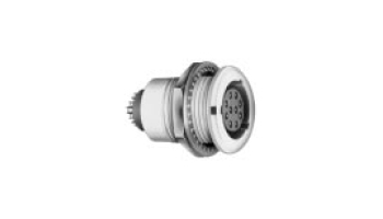
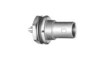
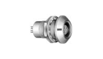
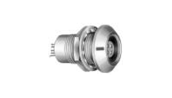
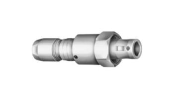
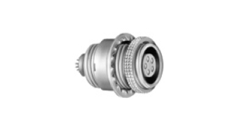
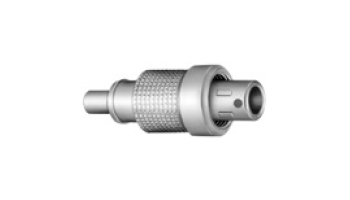
PEI-Genesis offers LEMO’s B Series push pull connector: a secure, push pull latching system with high-density panel spacing, 360 degree EMI shielding and quick mating or unmating. This LEMO push pull connector series is designed for indoor or vacuum-tight applications, making it an ideal choice for test and measurement instrumentation, medical devices, research, audio/video and applications where a highly reliable, quick-mating connector is needed. Modular insert configurations include a wide range of high-density or hybrid electrical contacts, including solder, crimp, PCB straight or elbow, fiber, coax, thermocouple, pneumatic, fluidic or high voltage contacts. LEMO’s proprietary keying system allows for a higher contact density while preventing mismating. This LEMO push pull connector series includes the family size range of 0B to 5B. PEI-Genesis’ Value Add Services are available for the LEMO B Series with rapid turnaround. Contact us today to discuss your next application.
|
FEATURESLEMO B SERIES CONNECTOR FEATURES
MATERIALS & FINISHESLEMO B SERIES CONNECTOR MATERIALS & FINISHES
Shell Brass, Stainless Steel, Aluminum alloy
Shell Plating Chrome, Nickel, Black Chrome, Anodized, Nickel Antracite
Contacts Brass or Bronze Beryllium with Stainless Steel Clips
Contact Platings Gold over Nickel over Copper
Insulator PEEK, PSU, PPSU, PA 6.6
O-ring and Gaskets Silicone
ELECTRICAL DATALEMO B SERIES CONNECTOR ELECTRICAL DATA
Test Voltage (Ue) Test Voltage is dependant on contact and shell size, along with Insert Configuration. See Insert Configuration Table. It corresponds to 75% of the mean breakdown voltage. Test voltage is applied at 500 V/s and the test duration is 1 minute. This test has been carried out with a mated plug and socket, with power supply only on the plug end. Operating Voltage (Us): It is proposed according to the following ratio : Us = Ue/3 Voltage values are given in the table on insulator types for each series. They correspond with values measured at sea level. They are adapted to all applications up to an altitude of 2000m. In case a device is used at a higher altitude, air clearance between live parts has to be multiplied by the following coefficients. It means also that test voltage has to be divided by this coefficients. Altitude (m) Coefficient 2000 1.00 3000 1.14 4000 1.29 5000 1.48 Electrical Data - Current Rating Current Rating is dependant on contact and shell size, along with Insert Configuration. See Insert Configuration Table. The specified rated current can be applied simultaneously to all the contacts. It corresponds with an average temperature rise of 40°C of the connector. 
MECHANICALLEMO B SERIES CONNECTOR MECHANICAL
Wire Range Sizes 30-8AWG AWG (stranded) or 28-10 AWG (solid)
Mating Life >5,000 cycle, per IEC 60512-5 test 9a
Salt Spray >144 hours, per IEC 60512-6 test 11F
Operating Temperature -55°C to +250°C (-67°F to 482°F)
Protection Index (mated) IP50, per IEC 60529, IP68 vacuumtight
Humidity Up to 95% at 60°C
Vibration 10-2000 Hz, 15g per, IEC 60512-4 test 6d
Shock 100g, 6ms, per IEC 60512-4 test 6c
Shielding Efficiency at 10 MHz >75 dB, per IEC 60169-1-3
at 1 GHz >40 dB, per IEC 60169-1-3 Contact Type Solder, Crimp, PCB (straight & right angle), thermocouple, co-ax, fiber optic, high voltage, first-mate last-break
Number of Circuits 2 to 64 (See Insert Configuration Table)
Polarization Integral Key(s) and Keyway(s)
Insert Material Characteristics PEEK PSU PPSU Standard Color Natural (beige) White or Grey Cream - Temperature range - 50° C/+250° C - 50° C/+150° C - 50° C/+180° C - Sterilization resistance* >200 Cycles ~20 Cycles >100 Cycles IEC 60601-1 § 44.7 Resistance to solvents Very good Limited Good - Contact Resistance with Relation to the Number of Mating Cycles Average values measured after the mating cycles and the salt spray test according to IEC 60512-6 test 11f. Contact Resistance (m ohm symbol) A ø (mm) 1000 Cycles 3000 Cycles 5000 Cycles 0.5 7.5 8.3 8.7 0.7 5.6 5.7 6.1 0.9 4.1 4.2 4.8 1.3 2.8 2.9 3.6 1.6 2.6 2.7 3.5 2.0 2.9 3.1 3.3 3.0 2.0 2.2 3.1 4.0 1.6 2.0 2.8 5.0 1.4 - - 6.0 1.2 - - 8.0 0.8 - - 12.0 0.7 - - Insulation Resistance Between the Contacts and Contact/Shell Multipole Unipole Insulating Material PEEK PTFE New > 1012 ohms > 1012 ohms After Humidity Test 1) > 1010 ohms > 1010 ohms Note: 1) 21 days at 95% RH according to IEC 60068-2-3. Contact Retention Force - Crimp Contacts Solder contacts are pressed fit and will have higher retention force. Contact Size Retention Axial Load (Newtons) 0.5 12 0.7 22 0.9 30 1.3 40 1.6 50 2.0 65 3.0 75 4.0 90 |
|
LEMO B SERIES CONNECTOR APPLICATIONS
|
|
MALE CONTACTSLEMO B SERIES CONNECTOR CONTACTS & TOOLING - MALE CONTACTS
Male (Pin) Crimp Contacts & Tooling Shell Size Contact Size Contact Type Wire Range Wire Range Contact Part Number Crimp Tool Positioner/Turret Extraction Tool
0.035 - 0.090
0.9 0.9 0.9 0.7 0.7 0.5 C B G C B C 24 - 20 26 - 22 32 - 28 26 - 22 32 - 28 32 - 28 0.250 - 0.500 0.140 - 0.340 0.035 - 0.090 0.140 - 0.340 0.035 - 0.090 0.035 - 0.090 FGG.0B.560.ZZC FGG.0B.561.ZZC FGG.0B.562.ZZC FGG.0B.555.ZZC FGG.0B.556.ZZC FGG.0B.554.ZZC
DCE.91.050.BVC
DCF.91.050.2LT
1.3 1.3 0.9 0.9 0.7 0.7 0.5 C B C B C B C 20 - 18 24 - 20 24 - 20 26 - 22 26 - 22 32 - 28 32 - 28 0.500 - 1.00 0.250 - 0.500 0.250 - 0.500 0.140 - 0.340 0.140 - 0.340 0.035 - 0.090 0.035 - 0.090 FGG.1B.565.ZZC FGG.1B.566.ZZC FGG.1B.560.ZZC FGG.1B.561.ZZC FGG.1B.555.ZZC FGG.1B.556.ZZC FGG.1B.554.ZZC
DCE.91.051.BVC
DCF.91.050.2LT
2.0 2.0 1.6 1.6 1.3 1.3 1.3 0.9 0.9 0.9 0.7 0.7 C B C B C B G C B G C B 16 - 12 18 - 14 18 - 14 22 - 18 20 - 18 24 - 20 26 - 22 24 - 20 26 - 22 32 - 28 26 - 22 32 - 28 1.50 - 2.50 1.00 - 1.50 1.00 - 1.50 0.340 - 1.00 0.500 - 1.00 0.250 - 0.500 0.140 - 0.340 0.250 - 0.500 0.140 - 0.340 0.035 - 0.090 0.140 - 0.340 0.035 - 0.090 FGG.2B.575.ZZC FGG.2B.576.ZZC FGG.2B.570.ZZC FGG.2B.571.ZZC FGG.2B.565.ZZC FGG.2B.566.ZZC FGG.2B.567.ZZC FGG.2B.560.ZZC FGG.2B.561.ZZC FGG.2B.562.ZZC FGG.2B.555.ZZC FGG.2B.556.ZZC
DCE.91.132.CVC
DCE.91.092.AVC
3.0 2.0 2.0 1.6 1.6 1.3 1.3 0.9 0.9 0.9 0.7 0.7 C C B C B C B C B G C B 14 - 10 16 - 12 18 - 14 18 - 14 22 - 18 20 - 18 24 - 20 24 - 20 26 - 22 32 - 28 26 - 22 32 - 28 2.50 - 4.00 1.50 - 2.50 1.00 - 1.50 1.00 - 1.50 0.340 - 1.00 0.500 - 1.00 0.250 - 0.500 0.250 - 0.500 0.140 - 0.340 0.035 - 0.090 0.140 - 0.340 0.035 - 0.090 FGG.3B.580.ZZC FGG.3B.575.ZZC FGG.3B.576.ZZC FGG.3B.570.ZZC FGG.3B.571.ZZC FGG.3B.565.ZZC FGG.3B.566.ZZC FGG.3B.560.ZZC FGG.3B.561.ZZC FGG.3B.562.ZZC FGG.3B.555.ZZC FGG.3B.556.ZZC DPC.91.102.V
DCE.91.303.BVCM
DCF.91.303.5LT
3.0 2.0 2.0 1.6 1.6 1.3 1.3 0.9 0.9 0.7 0.7 C C B C B C B C B C B 14 - 10 16 - 12 18 - 14 18 - 14 22 - 18 20 - 18 24 - 20 24 - 20 26 - 22 26 - 22 32 - 28 2.50 - 4.00 1.50 - 2.50 1.00 - 1.50 1.00 - 1.50 0.340 - 1.00 0.500 - 1.00 0.250 - 0.500 0.250 - 0.500 0.140 - 0.340 0.140 - 0.340 0.035 - 0.090 FGG.4B.580.ZZC FGG.4B.575.ZZC FGG.4B.576.ZZC FGG.4B.570.ZZC FGG.4B.571.ZZC FGG.4B.565.ZZC FGG.4B.566.ZZC FGG.4B.560.ZZC FGG.4B.561.ZZC FGG.4B.555.ZZC FGG.4B.556.ZZC DPC.91.102.V
DCE.91.304.BVCM
DCF.91.303.5LT
4.0 3.0 2.0 2.0 1.6 1.6 1.3 1.3 1.3 0.9 0.9 C C C B C B C B G C B 12 - 10 14 - 10 16 - 12 18 - 14 18 - 14 22 - 18 20 - 18 24 - 20 26 - 22 24 - 20 26 - 22 4.00 - 6.00 2.50 - 4.00 1.50 - 2.50 1.00 - 1.50 1.00 - 1.50 0.340 - 1.00 0.500 - 1.00 0.250 - 0.500 0.140 - 0.340 0.250 - 0.500 0.140 - 0.340 FGG.5B.582.ZZC FGG.5B.580.ZZC FGG.5B.575.ZZC FGG.5B.576.ZZC FGG.5B.570.ZZC FGG.5B.571.ZZC FGG.5B.565.ZZC FGG.5B.566.ZZC FGG.5B.567.ZZC FGG.5B.560.ZZC FGG.5B.561.ZZC
DCE.91.405.BVCM DCE.91.305.BVCM
DCF.91.405.5LT DCF.91.303.5LT
FEMALE CONTACTSLEMO B SERIES CONNECTOR CONTACTS & TOOLING - FEMALE CONTACTS
Female (Socket) Crimp Contacts & Tooling Shell Size Contact Size Contact Type Wire Range Wire Range Contact Part Number Crimp Tool Positioner/Turret Extraction Tool
0.035 - 0.090
0.9 0.9 0.9 0.7 0.7 M P U M P 24 - 20 26 - 22 32 - 28 26 - 22 32 - 28 0.250 - 0.500 0.140 - 0.340 0.035 - 0.090 0.140 - 0.340 0.035 - 0.090 EGG.0B.660.ZZM EGG.0B.661.ZZM EGG.0B.662.ZZM EGG.0B.655.ZZM EGG.0B.656.ZZM
1.3 1.3 0.9 0.9 0.7 0.7 M P M P M P 20 - 18 24 - 20 24 - 20 26 - 22 26 - 22 32 - 28 0.500 - 1.00 0.250 - 0.500 0.250 - 0.500 0.140 - 0.340 0.140 - 0.340 0.035 - 0.090 EGG.1B.665.ZZM EGG.1B.666.ZZM EGG.1B.660.ZZM EGG.1B.661.ZZM EGG.1B.655.ZZM EGG.1B.656.ZZM
2.0 2.0 1.6 1.6 1.3 1.3 1.3 0.9 0.9 0.9 0.7 0.7 M P M P M P U M P U M P 16 - 12 18 - 14 18 - 14 22 - 18 20 - 18 24 - 20 26 - 22 24 - 20 26 - 22 32 - 28 26 - 22 32 - 28 1.50 - 2.50 1.00 - 1.50 1.00 - 1.50 0.340 - 1.00 0.500 - 1.00 0.250 - 0.500 0.140 - 0.340 0.250 - 0.500 0.140 - 0.340 0.035 - 0.090 0.140 - 0.340 0.035 - 0.090 EGG.2B.675.ZZM EGG.2B.676.ZZM EGG.2B.670.ZZM EGG.2B.671.ZZM EGG.2B.665.ZZM EGG.2B.666.ZZM EGG.2B.667.ZZM EGG.2B.660.ZZM EGG.2B.661.ZZM EGG.2B.662.ZZM EGG.2B.655.ZZM EGG.2B.656.ZZM
DCE.91.132.CVM
DCE.91.092.AVM
3.0 2.0 2.0 1.6 1.6 1.3 1.3 0.9 0.9 0.9 0.7 0.7 M M P M P M P M P U M P 14 - 10 16 - 12 18 - 14 18 - 14 22 - 18 20 - 18 24 - 20 24 - 20 26 - 22 32 - 28 26 - 22 32 - 28 2.50 - 4.00 1.50 - 2.50 1.00 - 1.50 1.00 - 1.50 0.340 - 1.00 0.500 - 1.00 0.250 - 0.500 0.250 - 0.500 0.140 - 0.340 0.035 - 0.090 0.140 - 0.340 0.035 - 0.090 EGG.3B.680.ZZM EGG.3B.675.ZZM EGG.3B.676.ZZM EGG.3B.670.ZZM EGG.3B.671.ZZM EGG.3B.665.ZZM EGG.3B.666.ZZM EGG.3B.660.ZZM EGG.3B.661.ZZM EGG.3B.662.ZZM EGG.3B.655.ZZM EGG.3B.656.ZZM DPC.91.102.V
DCE.91.303.BVCM
DCF.91.303.5LT
3.0 2.0 2.0 1.6 1.6 1.3 1.3 0.9 0.9 0.7 0.7 M M P M P M P M P M P 14 - 10 16 - 12 18 - 14 18 - 14 22 - 18 20 - 18 24 - 20 24 - 20 26 - 22 26 - 22 32 - 28 2.50 - 4.00 1.50 - 2.50 1.00 - 1.50 1.00 - 1.50 0.340 - 1.00 0.500 - 1.00 0.250 - 0.500 0.250 - 0.500 0.140 - 0.340 0.140 - 0.340 0.035 - 0.090 EGG.4B.680.ZZM EGG.4B.675.ZZM EGG.4B.676.ZZM EGG.4B.670.ZZM EGG.4B.671.ZZM EGG.4B.665.ZZM EGG.4B.666.ZZM EGG.4B.660.ZZM EGG.4B.661.ZZM EGG.4B.655.ZZM EGG.4B.656.ZZM DPC.91.102.V
DCE.91.304.BVCM
DCF.91.303.5LT
4.0 3.0 2.0 2.0 1.6 1.6 1.3 1.3 1.3 0.9 0.9 M M M P M P M P U M P 12 - 10 14 - 10 16 - 12 18 - 14 18 - 14 22 - 18 20 - 18 24 - 20 26 - 22 24 - 20 26 - 22 4.00 - 6.00 2.50 - 4.00 1.50 - 2.50 1.00 - 1.50 1.00 - 1.50 0.340 - 1.00 0.500 - 1.00 0.250 - 0.500 0.140 - 0.340 0.250 - 0.500 0.140 - 0.340 EGG.5B.682.ZZM EGG.5B.680.ZZM EGG.5B.675.ZZM EGG.5B.676.ZZM EGG.5B.670.ZZM EGG.5B.671.ZZM EGG.5B.665.ZZM EGG.5B.666.ZZM EGG.5B.667.ZZM EGG.5B.660.ZZM EGG.5B.661.ZZM
DCE.91.405.BVCM DCE.91.305.BVCM
DCF.91.405.5LT DCF.91.303.5LT
|
|
METAL SHELLLEMO B SERIES CONNECTOR METAL SHELL DIMENSIONS
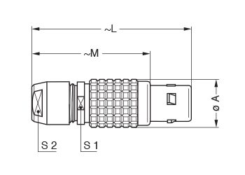
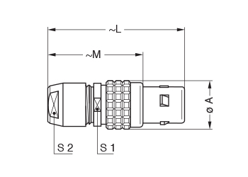
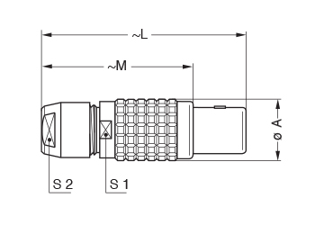
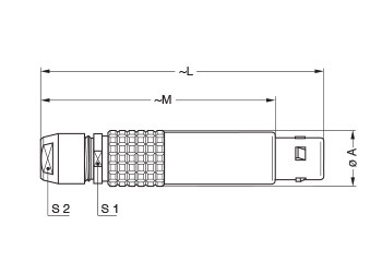
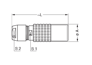
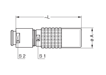
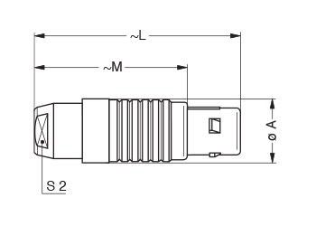
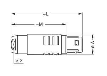
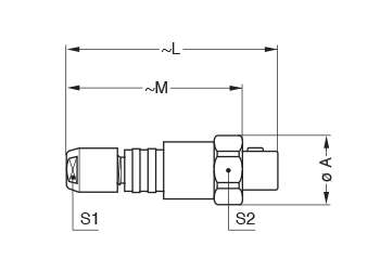
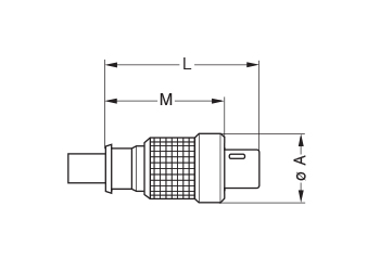
FGG Straight plug, key (G) or keys (A…M and R), cable collet
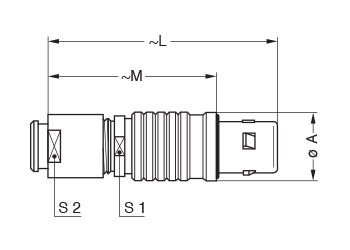
Reference Dimensions (MM) Model Series A L M S1 S2 FGG 00* 6.4 28.5 20.5 5.5 5 FGG 0B 9.5 36.0 26.0 8.0 7 FGG 1B 12.0 43.0 32.0 10.0 9 FGG 2B 15.0 50.0 38.0 13.0 12 FGG 3B 18.0 58.0 43.0 15.0 14 FGG 4B 25.0 75.0 57.0 21.0 20 FGG 5B 35.0 103.0 78.0 31.0 30 M1 Cable assembly (see assembly instructions) *The surface design of the 00 series is different FGG Straight plug, key (G) or keys (A…M), cable collet and nut for fitting a bend relief1
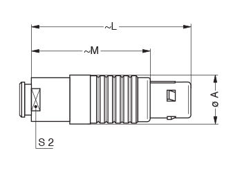
Reference Dimensions (MM) Model Series A L M S1 S2 FGG 002 6.4 28.7 20.7 5.5 6 FGG 0B 9.5 35.0 25.0 8.0 7 FGG 1B 12.0 42.0 31.0 10.0 9 FGG 2B 15.0 49.0 37.0 13.0 12 FGG 3B 18.0 56.5 41.5 15.0 15 FGG 4B 25.0 71.0 53.0 21.0 20 M1 Cable assembly (see assembly instructions) 1 To order, add a «Z» at the end of the reference. 2 The surface design of the 00 series is different. The bend relief must be ordered separately (see assembly instructions). JGG Straight plug, short version, key (G), cable collet
Reference Dimensions (MM) Model Series A L M S1 S2 JGG 0B 9.5 32.0 22.0 8.0 7 M4 Cable assembly (see assembly instructions) FFG Straight plug, non-latching, key (G) or keys (A…M), cable collet
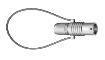
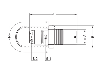
Reference Dimensions (MM) Model Series A L M S1 S2 FFG 0B 9.5 36 26 8 7 FFG 1B 12.0 43 32 10 9 FFG 2B 15.0 50 38 13 12 FFG 3B 18.0 58 43 15 14 FFG 4B 25.0 75 57 21 20 M1 Cable assembly (see assembly instructions) FNG Straight plug, key (G) or keys (A…M and R), cable collet and lanyard release
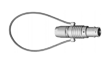
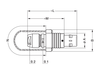
Reference Dimensions (MM) Model Series A B L M N S1 S2 FNG 0B 9.5 15.5 36.0 26.0 140 8 7 FNG 1B 12.0 18.0 43.0 32.0 140 10 9 FNG 2B 15.0 21.0 49.0 37.0 160 13 12 FNG 3B 18.0 25.0 58.0 43.0 190 15 14 FNG 4B 25.0 32.0 75.0 57.0 230 21 20 FNG 5B 35.0 42.0 103.0 78.0 300 31 30 M1 Cable assembly (see assembly instructions) Note: cable material: stainless steel with Polyamide sheath. FEG Straight plug, key (G) or keys (A…L), cable collet, front seal and nut for fitting a bend relief* (IP 54 protection index when mated)
Reference Dimensions (MM) Model Series A L M S1 S2 FEG 0B 11.0 35.0 25.0 8 7 FEG 1B 13.5 42.0 33.0 10 9 FEG 2B 16.5 48.0 36.0 13 12 FEG 3B 19.0 56.5 41.5 15 15 M1 Cable assembly (see assembly instructions) *To order, add a «Z» at the end of the reference. The bend relief must be ordered separately (see assembly instructions). FDG Straight plug, long version, key (G) or keys (A…L), cable collet
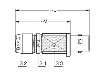
Reference Dimensions (MM) Model Series A L M S1 S2 FDG 1B 12 68 57 10 9 FDG 2B 15 79 67 13 12 M2 Cable assembly (see assembly instructions) FIG Straight plug for remote handling, key (G) or keys (A…L and R), special alignment mark, knurled handling surface, cable collet
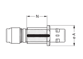
Reference Dimensions (MM) Model Series A L M N S1 S2 S3 FIG 2B 20 49 37 17.5 13 12 15 FIG 3B 22 58 43 21.5 15 14 18 FIG 4B 30 75 57 28.5 21 20 25 FIG 5B 40 103 78 41.0 31 30 35 M1 Cable assembly (see assembly instructions) FWG Fixed plug, nut fixing, key (G) or keys (A…L)
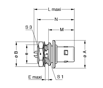
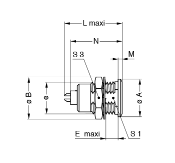
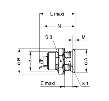
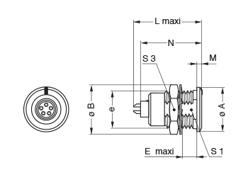
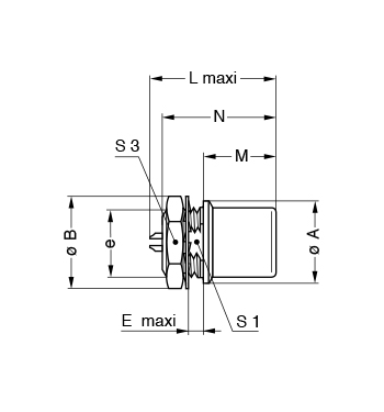
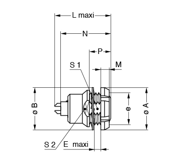
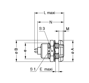
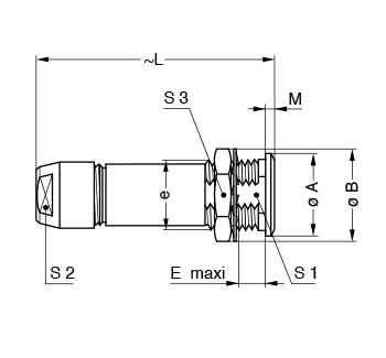
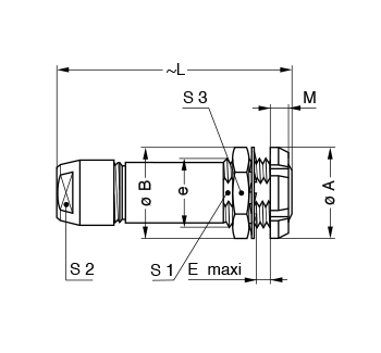
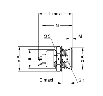
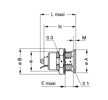
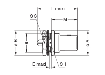
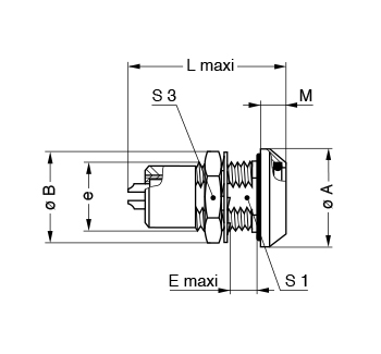
Reference Dimensions (MM) Model Series A B e E L M N* S1 S3 FWG 0B 14.0 12.4 M9x0.6 1.8 22.5 14.5 19.5 8.2 11 FWG 1B 18.0 15.8 M12x1.0 2.9 24.9 17.0 24.8 10.5 14 FWG 2B 19.5 19.2 M15x1.0 4.1 28.6 18.0 27.3 13.5 17 FWG 3B 25.0 25.0 M18x1.0 4.2 32.1 23.0 31.5 16.5 22 P9 Panel cut-out (see assembly instructions) * Maximum length with crimp contacts FAG Fixed plug, non-latching, nut fixing, key (G) or keys (A…M and R)
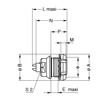
Reference Dimensions (MM) Model Series A B e E L M N* S1 S3 FAG 00 8 10.2 M7x0.5 2.9 18.1 9.0 15.0 6.3 9 FAG 0B 10 12.4 M9x0.6 4.2 20.8 11.5 18.9 8.2 11 FAG 1B 14 15.8 M12x1.0 5.4 25.2 12.5 21.6 10.5 14 FAG 2B 18 19.2 M15x1.0 6.0 28.7 13.8 23.9 13.5 17 FAG 3B 22 25.0 M18x1.0 5.8 32.1 17.0 30.2 16.5 22 FAG 4B 29 34.0 M25x1.0 6.8 37.1 20.5 34.7 23.5 30 FAG 5B 40 40.0 M35x1.0 6.8 47.1 28.0 42.8 33.5 - P1 Panel cut-out (see assembly instructions) *Maximum length with crimp contacts. The 5B series is delivered without locking washer or tapered washer and with a round nut. FHG Elbow (90°) plug, key (G) or keys (A…M and R), cable collet
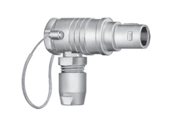
Reference Dimensions (MM) Model Series A D H L M S1 S2 S3 FHG 00* 7.7 5.2 18.0 24.5 16.5 7 5 5.5 FHG 0B 11.0 6.5 26.0 30.0 21.6 10 7 8.0 FHG 1B 13.5 8.0 30.5 36.0 25.0 11 9 10.0 FHG 2B 16.5 9.0 34.0 41.5 29.5 14 12 13.0 FHG 3B 19.0 10.0 37.0 50.0 35.0 17 14 15.0 FHG 4B 26.0 15.0 52.0 67.0 49.0 22 20 21.0 FHG 5B 36.0 21.0 74.0 90.0 65.0 32 30 31.0 M3 Cable assembly (see assembly instructions) * The surface design of the 00 series is different. FMG Elbow (90°) plug, key (G) or keys (A…M), cable collet and lanyard release, long key*
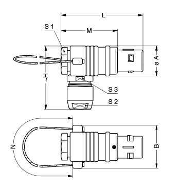
Reference Dimensions (MM) Model Series A B H L M N S1 S2 S3 FMG 0B 11 17 26 31.6 21.6 140 10 7 8 FMG 3B 19 26 39 50.0 35.0 190 17 14 15 M3 Cable assembly (see assembly instructions) *Long key: only in 0B series and with key (G). Cable material: stainless steel with Polyamide sheath. FKG Elbow (90°) plug for remote handling, key (G) or keys (A…L), special alignment mark, knurled handling surface, cable collet
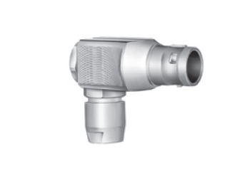
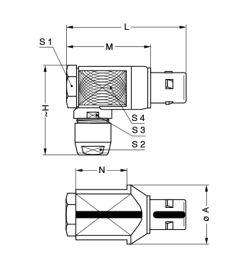
Reference Dimensions (MM) Model Series A H L M N S1 S2 S3 S4 FKG 3B 25.0 37.0 50.0 35.0 21.0 17.0 14.0 15.0 21.0 FKG 4B 32.0 52.0 67.0 49.0 28.5 22.0 20.0 21.0 26.0 FKG 5B 46.0 74.2 89.5 64.5 40.0 32.0 30.0 31.0 38.0 M3 Cable assembly (see assembly instructions) Note: dimension D is the same as for the FHG model EGG Fixed socket, nut fixing, key (G) or keys (A…M and R)
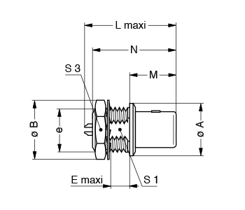
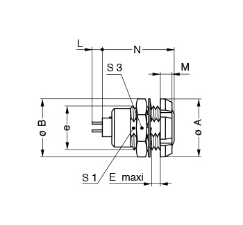
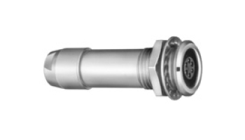
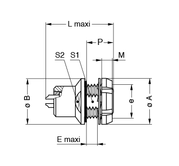
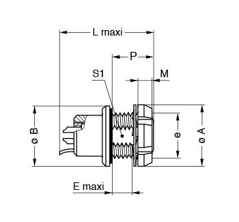
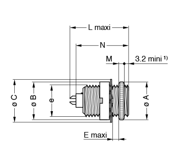
Reference Dimensions (MM) Model Series A B e E L M N* S1 S3 EGG 00 8.0 10.2 M7x0.5 6.0 15.5 1.0 13.7 6.3 9.0 EGG 0B 10.0 12.4 M9x0.6 7.0 20.7 1.2 19.1 8.2 11.0 EGG 1B 14.0 15.8 M12x1.0 7.5 23.0 1.5 21.1 10.5 14.0 EGG 2B 18.0 19.2 M15x1.0 8.5 26.7 1.8 24.6 13.5 17.0 EGG 3B 22.0 25.0 M18x1.0 11.5 30.7 2.0 28.1 16.5 22.0 EGG 4B 28.0 34.0 M25x1.0 12.0 35.7 2.5 34.1 23.5 30.0 EGG 5B 40.0 40.0 M35x1.0 11.0 43.5 3.0 39.6 33.5 - P1 Panel cut-out (see assembly instructions) Note: *Maximum length with crimp contacts. The 5B series is delivered with a tapered washer and a round nut. ENG Fixed socket with earthing tag, nut fixing, key (G) or keys (A…M)
Reference Dimensions (MM) Model Series A B e E L M N1 S1 S3 ENG 0B 10.0 12.4 M9x0.6 7.0 20.7 1.2 19.1 8.2 11.0 ENG 1B2 14.0 15.8 M12x1.0 7.5 23.0 1.5 21.1 10.5 14.0 ENG 2B 18.0 19.2 M15x1.0 8.5 26.7 1.8 24.6 13.5 17.0 ENG 3B 22.0 25.0 M18x1.0 11.5 30.7 2.0 28.1 16.5 22.0 ENG 4B 28.0 34.0 M25x1.0 12.0 35.7 2.5 34.1 23.5 30.0 P1 Panel cut-out (see assembly instructions) Note: 1 Maximum length with crimp contacts. 2 For the 1B series the earthing tag is on the same side of the key. EKG Fixed socket, nut fixing, key (G) or keys (A…L and R), special alignment mark on the front
Reference Dimensions (MM) Model Series A B e E L M N* S1 S3 EKG 2B 18.0 19.2 M15x1.0 8.5 26.7 1.8 24.6 13.5 17.0 EKG 3B 22.0 25.0 M18x1.0 11.5 30.7 2.0 28.1 16.5 22.0 EKG 4B 28.0 34.0 M25x1.0 12.0 35.7 2.5 34.1 23.5 30.0 EKG 5B 40.0 40.0 M35x1.0 11.0 43.5 3.0 39.6 33.5 - P1 Panel cut-out (see assembly instructions) Note: *Maximum length with crimp contacts. The 5B series is delivered with a tapered washer and a round nut. ESG Fixed socket with two round nuts, key (G) or keys (A…L), long threaded shell (back panel mounting)
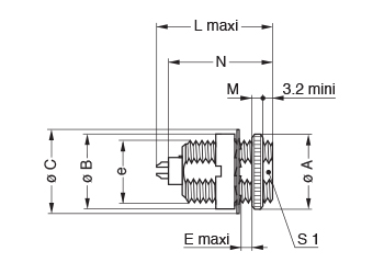
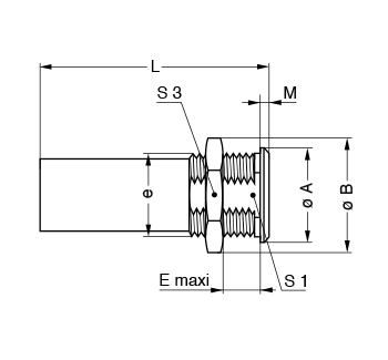
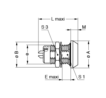
Reference Dimensions (MM) Model Series A B C e E L M N* S1 ESG 00 9.0 9.0 9.5 M7x0.5 3.2 15.5 2.0 13.7 - ESG 1B 14.0 14.0 16.0 M12x1.0 8.0 23.0 2.0 21.1 10.5 P1 Panel cut-out 1B series (see assembly instructions) P2 Panel cut-out 00 series (see assembly instructions) * Maximum length with crimp contacts. EHG Fixed socket, nut fixing, key (G) or keys (A…M and R), and protruding shell
Reference Dimensions (MM) Model Series A B e E L M N* S1 S3 EHG 00 8.0 10.2 M7x0.5 2.0 15.5 8.5 13.7 6.3 9.0 EHG 0B 10.0 12.4 M9x0.6 2.0 19.5 12.5 19.1 8.2 11.0 EHG 1B 14.0 15.8 M12x1.0 4.0 21.7 12.0 21.1 10.5 14.0 EHG 2B 18.0 19.2 M15x1.0 5.1 22.7 12.5 24.6 13.5 17.0 EHG 3B 22.0 25.0 M18x1.0 7.1 30.7 13.5 30.3 16.5 22.0 EHG 4B 40.0 40.0 M35x1.0 2.5 43.5 28.0 38.5 33.5 - P1 Panel cut-out (see assembly instructions) * Maximum length with crimp contacts. The 5B series is delivered without locking washer or tapered washer and with a round nut. EJG Fixed socket, press or adhesive fit, key (G) or keys (A…M)
Reference Dimensions (MM) Model Series A B L M N* EJG 0B 9.2 8.35 20.7 1.5 19.1 EJG 1B 12.5 11.20 23.0 1.5 21.1 EJG 2B 16.5 14.00 26.7 1.5 24.6 P5 Panel cut-out (see assembly instructions) * Maximum length with crimp contacts. EEG Fixed socket, nut fixing, key (G) or keys (A…M and R) (back panel mounting)
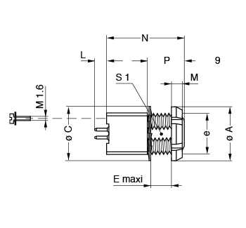
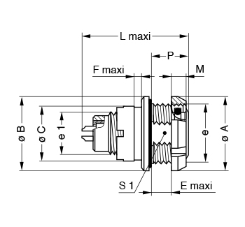
Reference Dimensions (MM) Model Series A B e E L M N* P S1 S2 EEG 00 10.0 9.5 M7x0.5 2.3 15.5 2.5 13.7 6.0 6.3 7.5 EEG 0B 12.0 12.5 M9x0.6 2.4 20.7 2.5 19.1 6.3 8.2 9.0 EEG 1B 16.0 16.0 M12x1.0 6.5 23.0 3.5 21.1 11.0 10.5 13.0 EEG 2B 20.0 20.0 M15x1.0 3.0 26.7 3.5 24.6 9.0 13.5 15.0 EEG 3B 24.0 25.0 M18x1.0 5.0 30.7 4.5 28.1 12.0 16.5 20.0 EEG 5B 41.0 40.0 M35x1.0 13.5 43.5 5.0 39.6 19.5 33.5 38.0 P1 Panel cut-out (see assembly instructions) * Maximum length with crimp contacts. The 3B and 5B series are delivered with a conical nut. The 5B series is delivered without locking washer or tapered washer. EFG Fixed socket, nut fixing, key (G) or keys (A…M), with two flats on the shell and O-ring (back panel mounting)
Reference Dimensions (MM) Model Series A B e E L M N* P S2 EFG 0B 12.0 12.5 M9x0.6 5.5 20.7 2.5 19.1 9.0 8.0 P2 Panel cut-out (see assembly instructions) * Maximum length with crimp contacts. ECG Fixed socket with two nuts, key (G) or keys (A…M and R) (back panel mounting)
Reference Dimensions (MM) Model Series A B e E L M N* S1 S3 ECG 00 10.0 10.2 M7x0.5 4.3 13.7 2.5 13.7 6.3 9.0 ECG 0B 12.0 12.4 M9x0.6 5.5 20.7 2.5 19.1 8.2 11.0 ECG 1B 16.0 15.8 M12x1.0 6.0 23.0 3.5 21.1 10.5 14.0 ECG 2B 20.0 19.2 M15x1.0 6.5 26.7 3.5 24.6 13.5 17.0 ECG 3B 24.0 25.0 M18x1.0 9.0 30.7 4.5 28.1 16.5 22.0 ECG 4B 30.0 34.0 M25x1.0 10.0 35.7 4.5 32.6 23.5 30.0 ECG 5B 41.0 40.0 M35x1.0 9.0 43.5 5.0 39.6 33.5 - P1 Panel cut-out (see assembly instructions) Note: *Maximum length with crimp contacts. The 3B, 4B and 5B series are delivered with a conical nut. The 5B series is delivered with a tapered washer and a round nut. ECG Fixed socket with two nuts, key (G) or keys (A…F and R) and straight contact for printed circuit (back panel mounting)
Reference Dimensions (MM) Model Series A B e E M N S1 S3 ECG 00 10.0 10.2 M7x0.5 4.3 2.5 13.7 6.3 9.0 ECG 0B 12.0 12.4 M9x0.6 5.5 2.5 16.1 8.2 11.0 ECG 1B 16.0 15.8 M12x1.0 6.0 3.5 19.8 10.5 14.0 ECG 2B 20.0 19.2 M15x1.0 6.5 3.5 21.8 13.5 17.0 ECG 3B 24.0 25.0 M18x1.0 9.0 4.5 25.8 16.5 22.0 ECG 4B 30.0 34.0 M25x1.0 10.0 4.5 29.8 23.5 30.0 ECG 5B 41.0 40.0 M35x1.0 9.0 5.0 36.8 33.5 - P1 Panel cut-out (see assembly instructions) P15 PCB drilling pattern (see assembly instructions) Note: This contact type is available for E●● socket models fitted with female contacts. Length «L» depends on the number of contacts, see table in assembly instructions. The 5B series is delivered with a tapered washer and a round nut. The 3B, 4B and 5B series are delivered with a conical nut. ECG Fixed socket with two nuts, key (G) or keys (A…F) with elbow (90°) contact for printed circuit (back panel mounting)
Reference Dimensions (MM) Model Series A B e E M N S1 S3 ECG 0B 12.0 12.4 M9x0.6 5.5 2.5 18.3 8.2 11.0 ECG 1B 16.0 15.8 M12x1.0 6.0 3.5 20.3 10.5 14.0 ECG 2B 20.0 19.2 M15x1.0 6.5 3.5 22.3 13.5 17.0 ECG 3B 24.0 25.0 M18x1.0 9.0 4.5 25.8 16.5 22.0 P1 Panel cut-out (see assembly instructions) P17 PCB drilling pattern (see assembly instructions) Note: This female contact type is available for all back panel mounting socket models. Length «L» depends on the number of contacts, see PCB drilling pattern in assembly instructions. For male contacts, sockets are available upon request, with J, K or L keys. The 3B series is delivered with a conical nut. EZG Straight socket for printed circuit, key (G) or keys (A, B)
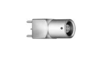
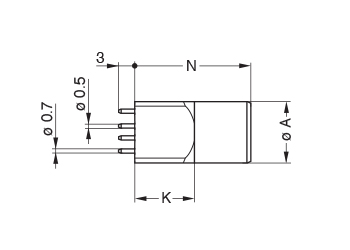
Reference Dimensions (MM) Model Series A B H K N EZG 00 6.8 7.0 5.08 7.0 14.0 P15 + P16 PCB drilling pattern (see assembly instructions) EZG Straight socket for printed circuit, key (G) or keys (A…F)
Reference Dimensions (MM) Model Series A B H K N EZG 0B 9.0 10.0 7.62 8.0 15.0 EZG 1B 11.0 12.0 7.62 8.0 19.0 EZG 2B 14.0 15.0 10.16 9.0 22.5 P15 + P16 PCB drilling pattern (see assembly instructions) Note: Length «L» depends on the number of contacts, see table in assembly instructions. EYG Fixed socket for printed circuit, nut fixing, key (G) or keys (A...F)(back panel mounting)
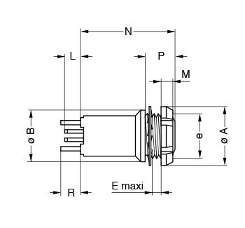
Reference Dimensions (MM) Model Series A B C D e E M N P S1 EYG 0B 12.0 10.0 12.5 7.62 M9x0.6 2.6 2.5 15.0 6.0 8.2 EYG 1B 14.0 12.0 16.0 7.62 M11x0.5 5.0 3.5 19.0 10.0 - EYG 2B 20.0 15.0 19.5 10.16 M15x1.0 7.5 3.5 22.5 13.5 13.5 P1 Panel cut-out 0B and 2B series (see assembly instructions) P10 Panel cut-out 1B series (see assembly instructions) P15 + P16 PCB drilling pattern (see assembly instructions) Note: Length «L» depends on the number of contacts, see assembly instructions. XPF Fixed socket, nut fixing, long shell, keys (F) for printed circuit (back panel mounting)
Reference Dimensions (MM) Model Series A B e E M N P R XPF 0B 12.0 11.0 M9x0.6 1.5 2.5 19.0 5.0 4.0 P2 Panel cut-out (see assembly instructions) P15 + P16 PCB drilling pattern (see assembly instructions) Note: Length «L» depends on the number of contacts, see table in assembly instructions. PHG Free socket, key (G) or keys (A…M and R), cable collet
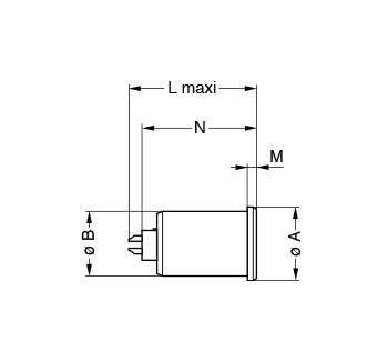
Reference Dimensions (MM) Model Series A L S1 S2 PHG 00 6.8 26.0 5.5 5.0 PHG 0B 9.5 35.5 8.0 7.0 PHG 1B 12.5 40.5 10.0 9.0 PHG 2B 16.5 47.0 13.0 12.0 PHG 3B 19.0 56.0 15.0 14.0 PHG 4B 26.0 73.0 21.0 20.0 PHG 5B 36.0 99.0 31.0 30.0 M1 Cable assembly (see assembly instructions) Note: 1) the surface design of the 00 series is different. PHG Free socket, key (G) or keys (A…M), cable collet and nut for fitting a bend relief1
Reference Dimensions (MM) Model Series A L S1 S2 PHG 002 6.8 34.0 5.5 6.0 PHG 0B 9.5 34.5 8.0 7.0 PHG 1B 12.5 39.5 10.0 9.0 PHG 2B 16.5 46.0 13.0 12.0 PHG 3B 19.0 54.5 15.0 15.0 PHG 4B 26.0 69.0 21.0 20.0 M1 Cable assembly (see assembly instructions) Note: 1 To order, add a «Z» at the end of the reference. 2 The surface design of the 00 series is different. The bend relief must be ordered separately (see assembly instructions). PNG Free socket, nut fixing, key (G) or keys (A…L and R), cable collet with lanyard release
Reference Dimensions (MM) Model Series A B L N S1 S2 PNG 1B 12.4 18.4 40.5 140.0 10.0 9.0 PNG 2B 16.5 22.5 47.0 160.0 13.0 12.0 PNG 3B 19.0 26.0 56.0 190.0 15.0 14.0 PNG 4B 26.0 33.0 73.0 230.0 21.0 20.0 PNG 5B 36.0 43.0 99.0 300.0 31.0 30.0 M1 Cable assembly (see assembly instructions) Note: cable material: stainless steel with Polyamide sheath PKG Fixed socket, nut fixing, key (G) or keys (A…M and R), cable collet
Reference Dimensions (MM) Model Series A B e E L M S1 S2 S3 PKG 00 8.0 10.2 M7x0.5 6.5 26.0 1.0 6.3 5.0 9.0 PKG 0B 10.0 12.4 M9x0.6 7.0 35.5 1.2 8.2 7.0 11.0 PKG 1B 14.0 15.8 M12x1.0 7.5 40.5 1.5 10.5 9.0 14.0 PKG 2B 18.0 19.2 M15x1.0 8.5 47.0 1.8 13.5 12.0 17.0 PKG 3B 22.0 25.0 M18x1.0 11.5 56.0 2.0 16.5 14.0 22.0 PKG 4B 28.0 34.0 M25x1.0 12.0 73.0 2.5 23.5 20.0 30.0 PKG 5B 40.0 40.0 M35x1.0 11.0 99.0 3.0 33.5 30.0 - P1 Panel cut-out (see assembly instructions) M1 Cable assembly (see assembly instructions) Note: the 5B series is delivered with a tapered washer and a round nut. PFG Fixed socket, with two nuts, key (G) or keys (A…M and R), cable collet (back panel mounting)
Reference Dimensions (MM) Model Series A B e E L M S1 S2 S3 PFG 00 10.0 10.2 M7x0.5 5.3 26.0 2.5 6.3 5.0 9.0 PFG 0B 12.0 12.4 M9x0.6 5.0 35.5 2.5 8.2 7.0 11.0 PFG 1B 16.0 15.8 M12x1.0 5.0 40.5 3.5 10.5 9.0 14.0 PFG 2B 20.0 19.2 M15x1.0 6.5 47.0 3.5 13.5 12.0 17.0 PFG 3B 24.0 25.0 M18x1.0 9.0 56.0 4.5 16.5 14.0 22.0 PFG 4B 30.0 34.0 M25x1.0 11.0 73.0 4.5 23.5 20.0 20.0 PFG 5B 41.0 40.0 M35x1.0 10.0 99.0 5.0 33.5 30.0 - P1 Panel cut-out (see assembly instructions) M1 Cable assembly (see assembly instructions) Note: the 3B, 4B and 5B series are delivered with a conical nut. The 5B series is delivered with a tapered washer and a round nut. PEG Fixed socket, nut fixing, key (G) or keys (A…L), cable collet (back panel mounting)
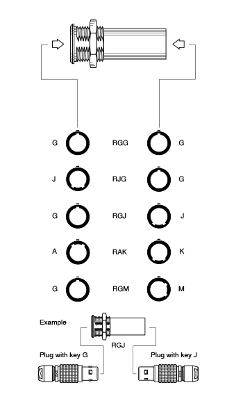
Reference Dimensions (MM) Model Series A B e E L M S1 S2 S4 P PEG 3B 24.0 25.0 M18x1.0 5.0 56.0 4.5 16.5 14.0 20.0 12.0 PEG 4B 32.0 34.0 M25x1.0 12.5 73.0 5.0 23.5 20.0 27.0 20.0 P1 Panel cut-out (see assembly instructions) M1 Cable assembly (see assembly instructions) Note: the 4B series has an o-ring on the flange. R ●● Fixed coupler, nut fixing, key (G) or keys (A and J) at the flange end and keys (J, K or M) at the other end
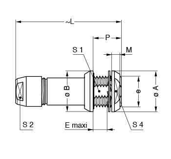
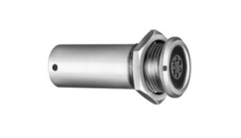
Reference Contacts Dimensions (MM) Model Series Type A B e E L M S1 S3 RGG1 0B Female - Female 12.0 13.8 M10x0.75 8.0 34.0 2.0 9.0 12.0 RGG2 0B Female - Female 12.0 13.8 M10x0.75 8.0 43.0 2.0 9.0 12.0 RJG RGJ RAK RGM
Male - Female Female - Male Female - Male Female - Male
RGG3 1B Female - Female 16.0 19.2 M14x1.00 8.5 47.0 2.5 12.5 17.0 RJG RGJ
Male - Female Female - Male
RJG RGJ
Male - Female Female - Male
RGJ 3B Female - Male 25.0 27.0 M20x1.00 32.0 53.0 4.0 18.5 24.0 RGJ 4B Female - Male 34.0 34.0 M25x1.0 50.0 65.0 4.0 23.5 30.0 P4 Panel cut-out (see assembly instructions) Note: 1 only available with two contacts. 2 only available with three and four contacts. 3 only available with three contacts. Alignment key see assembly instructions. For this fixed coupler, the first contact type mentioned is always the one at the flange end. On request, these couplers can be produced in other series, with other keys. ELBOW SOCKETLEMO B SERIES CONNECTOR ELBOW SOCKET DIMENSIONS
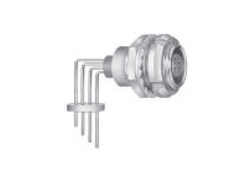
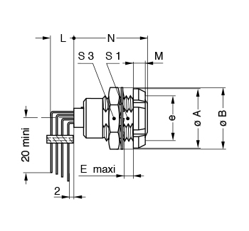
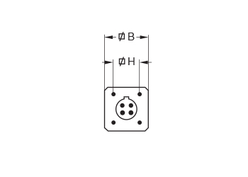
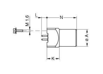
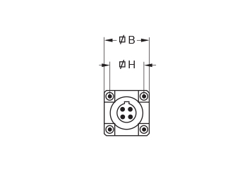
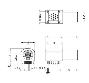
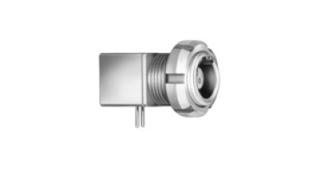
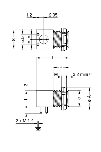
EPG Elbow (90°) socket for printed circuit, key (G) or keys (A…F) (solder or screw fixing)
Dimensions (MM) Reference A D H I K L N EPG.1B.314.NLN 11.0 21.0 7.7 14.3 19.0 36.0 15.4 P20 PCB drilling pattern (see assembly instructions) Note: to replace the 4 ground pins by 4 screws (M1.6) add an «S» to the end of the part number. (e.g.: EPG.1B.314.NLNS) EPG Elbow (90°) socket for printed circuit, key (G) or keys (A…F) (solder or screw fixing)
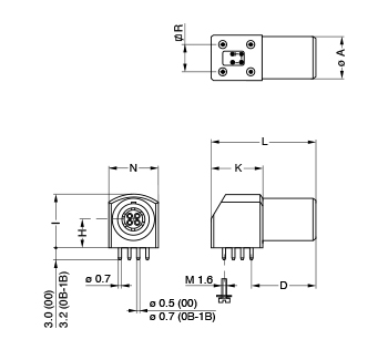
Dimensions (MM) Reference A D H I K L N R EPG.00.302.HLN EPG.00.303.HLN EPG.00.304.HLN
EPG.0B.302.HLN EPG.0B.303.HLN EPG.0B.304.HLN EPG.0B.305.HLN EPG.0B.306.HLN EPG.0B.307.HLN EPG.0B.309.HLN
EPG.1B.302.HLN EPG.1B.303.HLN EPG.1B.304.HLN EPG.1B.305.HLN EPG.1B.306.HLN EPG.1B.307.HLN EPG.1B.308.HLN EPG.1B.310.HLN
P18 PCB drilling pattern 00 series (see assembly instructions) P19 PCB drilling pattern 0B, 1B series (see assembly instructions) Note: In the 0B and 1B series, it is possible to replace the 4 ground pins by 4 screws (M1.6) add an «S» to the end of the part number. (e.g.: EPG.0B.307.HLNS) EXG Elbow (90°) socket for printed circuit with two nuts, key (G) or keys (A…F) (solder or screw fixing, back panel mounting) XBG Elbow (90°) socket fixing nut for printed circuit, key (G) or keys (A, B) (back panel mounting)
Dimensions (MM) Reference A B D e E H I K L M N R S3 XBG.00.302.HLN XBG.00.303.HLN XBG.00.304.HLN
EXG.0B.302.HLN EXG.0B.303.HLN EXG.0B.304.HLN EXG.0B.305.HLN EXG.0B.306.HLN EXG.0B.307.HLN EXG.0B.309.HLN
EXG.1B.302.HLN EXG.1B.303.HLN EXG.1B.304.HLN EXG.1B.305.HLN EXG.1B.306.HLN EXG.1B.307.HLN EXG.1B.308.HLN EXG.1B.310.HLN
P2 Panel cut-out 00, 0B series (see assembly instructions) P10 Panel cut-out 1B series (see assembly instructions) Note: In the 0B and 1B series, it is possible to replace the 4 ground pins by 4 screws (M1.6) add an «S» to the end of the part number. (e.g.: EXG.0B.307.HLNS). P18 PCB drilling pattern 00 series (see assembly instructions) P19 PCB drilling pattern 0B, 1B series (see assembly instructions) PLASTIC SHELLLEMO B SERIES CONNECTOR PLASTIC SHELL DIMENSIONS
Note: Other models with plastic outer shell are available on request. FGG Straight plug, key (G or J), cable collet, PEEK outer shell
Reference Dimensions (MM) Model Series A L M S2 FGG 1B 13.5 43.0 32.0 10 FGG 3B 19.0 62.0 47.0 15 FGG 4B 26.0 78.5 60.5 20 M1 Cable assembly (see assembly instructions) FGG Straight plug, key (G or J), cable collet, PEEK outer shell and nut for fitting a bend relief 1)
Reference Dimensions (MM) Model Series A L M S2 Note on FGG 1B 13.5 42.2 31.2 10 for all collet type FGG 4B 26.0 83.2 65.2 20 only from collet M1 Cable assembly (see assembly instructions) Note: 1) to order, add a «Z» at the end of the reference. The bend relief must be ordered separately (see assembly instructions). FGY Straight plug, keys (Y), cable collet and PSU or PPSU outer shell
Reference Dimensions (MM) Model Series A L M S2 FGY 2B 16.5 50.5 39.5 13 FGY 3B 19.0 58.0 43.0 15 FGY 4B 26.0 76.2 58.2 20 M1 Cable assembly (see assembly instructions) FGY Straight plug, keys (Y), cable collet and PSU or PPSU outer shell and nut for fitting a bend relief*
Reference Dimensions (MM) Model Series A L M S2 Note on FGY 2B 16.5 49.5 38.5 13 only for collet FGY 3B 19.0 56.5 41.5 15 only for collet FGY 4B 26.0 74.4 56.4 20 only for collet M1 Cable assembly (see assembly instructions) *To order, add a «Z» at the end of the reference. The bend relief must be ordered separately (see assembly instructions). ENG Fixed socket with earthing tag, nut fixing, key (G or J), PEEK outer shell
Reference Dimensions (MM) Model Series A B e E L M N* S1 S3 ENG 1B 14 15.8 M12x1.0 7.5 23.0 1.5 21.1 10.5 14 ENG 3B 22 25.0 M18x1.0 11.5 30.7 2.0 28.1 16.5 22 ENG 4B 28 34.0 M25x1.0 12.0 35.7 2.5 32.6 23.5 30 P1 Panel cut-out (see assembly instructions) *Maximum length with crimp contacts. ENY Fixed socket with earthing tag, nut fixing, keys (Y), PSU or PPSU outer shell
Reference Dimensions (MM) Model Series A B e E L M N* S1 S3 ENY 2B 18 19.2 M15x1.0 8.5 26.7 1.8 24.6 13.5 17 ENY 3B 22 25.0 M18x1.0 11.5 30.7 2.0 28.1 16.5 22 ENY 4B 28 34.0 M25x1.0 12.0 35.7 2.5 32.6 23.5 30 P1 Panel cut-out (see assembly instructions) *Maximum length with crimp contacts. WATER TIGHTLEMO B SERIES CONNECTOR WATER-TIGHT OR VACUUM-TIGHT DIMENSIONS
YHG Fixed plug, nut fixing, non-latching, key (G) or keys (A…M)
Reference Dimensions (MM) Model Series A B e E L M S1 S3 YHG 0B 13.0 12.4 M9x0.6 2.4 24.1 14.2 8.2 11 YHG 1B 16.0 15.8 M12x1.0 3.9 28.0 16.2 10.5 14 YHG 2B 19.0 19.2 M15x1.0 5.5 33.1 17.8 13.5 17 YHG 3B 22.0 25.0 M18x1.0 5.1 38.2 22.2 16.5 22 P9 Panel cut-out (see assembly instructions) Note: This model does not include an O-ring behind the flange, it ensures only IP61 protection index. Consequently, it is not vacuumtight. Water- tightness (when mated) is only ensured with HHG and HCG sockets. HGG Fixed socket, nut fixing, key (G) or keys (A…M and R), watertight or vacuumtight
Reference Dimensions (MM) Model Series A B e E L M S1 S3 HGG 00 11 10.2 M7x0.5 8.0 18.0 1.5 – 9 HGG 0B 13 12.4 M9x0.6 7.0 21.5 3.0 8.2 11 HGG 1B 18 15.8 M12x1.0 7.0 26.6 4.5 10.5 14 HGG 2B 20 19.2 M15x1.0 8.0 31.6 4.0 13.5 17 HGG 3B 25 25.0 M18x1.0 11.5 36.1 4.0 16.5 22 HGG 4B 34 34.0 M25x1.0 11.0 43.1 4.0 23.5 30 HGG 5B 45 40.0 M35x1.0 11.0 53.6 5.0 33.5 - P9 Panel cut-out (see assembly instructions) Note: the 5B series is delivered with a tapered washer and a round nut. HNG Fixed socket, nut fixing, with earthing tag, key (G) or keys (A…M), watertight or vacuumtight
Reference Dimensions (MM) Model Series A B e E L M S1 S3 HNG 0B 13 12.4 M9x0.6 7.0 21.5 3.0 8.2 11 P9 Panel cut-out (see assembly instructions) HHG Fixed socket, nut fixing, key (G) or keys (A…M), watertight or vacuumtight (watertight when mated)
Reference Dimensions (MM) Model Series A B e E L M S1 S3 HHG 0B 13.0 12.4 M9x0.6 7.0 24.5 4.8 8.2 11 HHG 1B 18.0 15.8 M12x1.0 7.0 30.3 5.2 10.5 14 HHG 2B 22.0 19.2 M15x1.0 8.0 35.6 6.0 13.5 17 HHG 3B 25.0 25.0 M18x1.0 11.5 41.3 7.2 16.5 22 P9 Panel cut-out (see assembly instructions) Note: This model ensures watertightness (IP66) in the mating area when mated with FGG or similar plug. HCG Fixed socket, nut fixing, key (G) or keys (A…M), watertight or vacuumtight (watertight when mated, back panel mounting)
Reference Dimensions (MM) Model Series A B C e e1 E F L M HCG 0B 18 18 12.0 M14x1.0 M9x0.6 3.9 1.0 24.5 3.5 HCG 1B 20 20 14.5 M16x1.0 M12x1.0 6.2 2.0 30.3 3.5 HCG 2B 24 24 17.5 M19x1.0 M14x1.0 6.7 1.5 35.6 3.5 P3 Panel cut-out (see assembly instructions) Note: this model ensures watertightness (IP66) in the mating area when mated with FGG or similar plug. HEG Fixed socket, nut fixing, key (G) or keys (A…M), watertight or vacuumtight (back panel mounting)
Reference Dimensions (MM) Model Series A B e E L M P S1 HEG 00 10 11 M7x0.5 2.5 18.2 2.5 6.0 6.3 HEG 0B 12 13 M9x0.6 5.5 21.5 2.5 9.0 8.2 HEG 1B 16 18 M12x1.0 6.5 26.6 3.5 11.0 10.5 HEG 2B 20 20 M15x1.0 5.0 31.6 3.5 9.6 13.5 P9 Panel cut-out (see assembly instructions) HMG Fixed socket with earthing tag, nut fixing, key (G) or keys (A…M), watertight or vacuumtight (back panel mounting)
Reference Dimensions (MM) Model Series A B e E L M P S1 HMG 00 10 11 M7x0.5 2.5 18.0 2.5 6.0 6.3 HMG 0B 12 13 M9x0.6 5.5 21.5 2.5 9.0 8.2 HMG 1B 16 18 M12x1.0 5.5 26.6 3.5 11.0 10.5 HMG 2B* 20 20 M15x1.0 5.5 31.6 3.5 9.6 13.5 HMG 3B 24 25 M18x1.0 7.5 36.1 4.5 14.0 16.5 P9 Panel cut-out (see assembly instructions) *The surface design of the 2B series is different. The 3B series is delivered with a conical nut. S ●● Fixed coupler, nut fixing, key (G) or keys (A, B, J, K and L) at the flange end and key (G) or keys (A, B, J, K and L) at the other end, watertight or vacuumtight
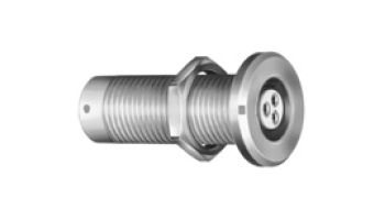
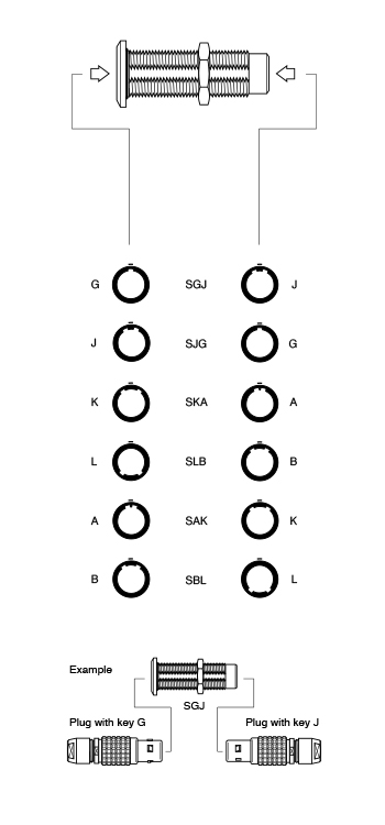
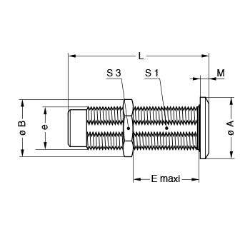
Reference Contacts Dimensions (MM) Model Series Type A B e E L M S1 S3 SGJ SJG 0B female–male male–female 14 13.8 M10x0.75 17 34 2.0 9.0 12 SGJ SJG 1B female–male male–female 17 15.8 M12x1.00 28 39 2.5 10.5 14 SGJ SJG 2B female–male male–female 20 21.5 M16x1.00 25 44 4.0 15.0 19 SGJ SJG SAK SBL 3B female–male male–female female–male female–male 25 27.0 M20x1.00 30 53 4.0 18.5 24 SAK SBL SGJ SJG 4B female–male female–male female–male male–female 34 34.0 M25x1.00 50 65 4.0 23.5 30 SGJ SJG SKA SLB SAK SBL 5B female–male male–female male–female male–female female–male female–male 45 40.0 M35x1.00 58 80 5.0 33.5 - P4 Panel cut-out (see assembly instructions) P9 Panel cut-out 1B series (see assembly instructions) Alignment key see assembly instructions. Note: for this fixed coupler, the first contact type mentioned is always the one at the flange end. On request these couplers can be produced in other series, with other keys. The 5B series is delivered with a round nut. BRIDGE MODELSLEMO B SERIES CONNECTOR BRIDGE MODELS DIMENSIONS
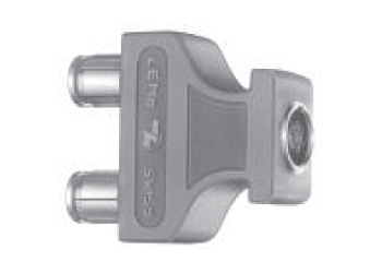
CFF Bridge plug with two non-latching plugs CRG Bridge plug with two non-latching plugs, and monitoring socket, key (G) or keys (A…M) CRG CFF
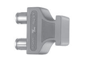
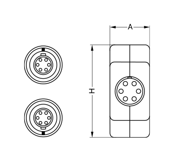
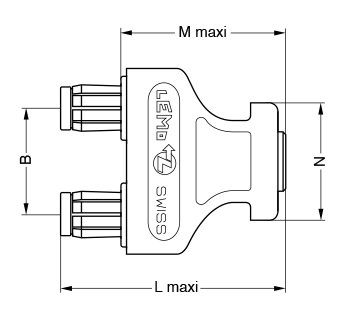
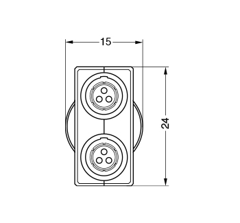
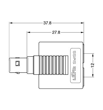
Reference Dimensions (MM) Model Series A B H L M N CFF-CRG 0B 13.5 14 27.5 37.2 27.2 22.5 CFF-CRG 1B 15.0 20 35.0 42.0 31.0 22.0 Note: in order to provide the user with a coding system, the bridge plug housing, the double panel washers and the bend reliefs are available in nine colours. FTG Straight plug, key (G) and two parallel sockets
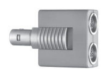
Reference Number of Contacts Test Voltage (kV rms) Rated Current (A) FTG.0B.302.PLFG 2 1.05 4 FTG.0B.303.PLFG 3 0.80 4 FTG.0B.304.PLFG 4 0.80 3
THREADED LATCHINGLEMO B SERIES CONNECTOR THREADED-LATCHING MODELS DIMENSIONS
FVG Straight plug, key (G) or keys (B), cable collet
Reference Dimensions (MM) Model Series A L M S1 S2 FVG 0 9 28.5 24 5 8 Note: to be ordered with nut for fitting a bend relief to obtain the rating IP 64. ESG Fixed socket with two round nuts, key (G) or keys (B), long threaded shell (back panel mounting)
Reference Dimensions (MM) Model Series A B C e E L M N ESG 0 9 9 9.5 M7X0.5 3.2 15.5 2 13.7 P2 Panel cut-out (see assembly instructions) Note: 1) minimum length of free thread to ensure mating. FVB Straight plug, keys (B), short shell for special cable crimping and for fitting a bend relief
Reference Dimensions (MM) Model Series A L M FVB 00 9 20 15.4 Note: after assembly the special bend relief GMF.00.018.D● (to be ordered separately) is to be fitted. XRB Elbow (90⁰) socket for printed circuit, keys (B), short shell with one nut, screw fixing (back panel mounting)
Reference Dimensions (MM) Model Series A e l L M P XRB 00 10 M7x0.5 7 14 2.5 7 |
|
CRIMP/SOLDER CONTACTSLEMO B SERIES CONNECTOR CRIMP/ SOLDER CONTACTS
Plugs and Receptacles with cable collet
STEP 1: Strip the cable according to the dimensions indicated in Cable Stripping Lengths Table. For connectors with solder contacts, the length L should be reduced to correspond with interior contact lengths. STEP 2: Slide the following onto the cable:
STEP 3: For solder contacts, solder the conductors to the contacts, making sure that the insulator (6) and the cable remain clean. STEP 4: For crimp contacts, fix the appropriate positioner onto the crimping tool and set the selector to the number corresponding to the AWG of the conductor used. Fit the conductor into the contact; make sure that the conductor is visible through the contact's inspection hole. Slide the contact-conductor assembly into the open crimping tool; make sure that the contact is pushed fully into the positioner. Close the tool. Remove from crimping tool and check that the conductor is secure in contact and shows in inspecion hole.
STEP 5: Arrange the contact-conductor assemblies according to the insert marking, avoiding any twisting of the conductors. Fit the contacts gently into the insulator (6); check that no conductor overlaps another and push the contacts into the insulator. Check that all the contacts are correctly located in the insulator by verifying the alignment of the contacts at the front of the insulator and by gently pulling on the insulator; the contact alignment must remain in correct position.
STEP 6: Position the midpiece with window (5) on the insulator; the window must be positioned exactly on the insulator's notch. Position the second midpiece, making sure that the two parts form a cylinder. CABLE STRIPPING LENGTHSLEMO B SERIES CONNECTOR CABLE STRIPPING LENGTHS
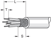
M1 Straight plugs and receptacles with cable collet (excluding long version plug, Model FD●)
Connector Cable Stripping Lengths (MM) M1 Contact Diameter Solder Crimp Series Type MM L S T L S T 00 302/303/304 0.5 7.0 4 2.5 10.0 4 3.0
302/303 304/305 306/307/3092) 0.9 0.7 0.5 13.0 13.0 14.0 7 7 7 3.0 3.0 2.5 17.0 17.0 18.0 7 7 7 4.0 4.0 3.0
302/303 304/305 306/307/308 310/314/316 1.3 0.9 0.7 0.5 14.0 14.0 14.0 16.5 8 8 8 8 3.5 3.0 3.0 2.5 18.0 18.0 18.0 - 8 8 8 - 4.0 4.0 4.0 -
302 303 304/305/ 308/310 312/314/316/ 326/332 2.0 1.6 1.3 0.9 0.7 0.5 19.0 19.0 18.0 17.0 17.0 17.0 9 9 9 9 9 9 4.0 3.5 3.5 3.0 3.0 2.5 22.0 22.0 20.0 20.0 20.0 - 9 9 9 9 9 - 5.5 5.5 4.0 4.0 4.0 -
302 303/304 305/306/307 308
310 312/314/ 320/322/324/ 3.0 2.0 1.6 1.3 1.3 2.0 1.3 0.9 0.7 24.0 23.0 23.0 22.0 22.0 22.0 22.0 21.0 21.0 10 10 10 10 10 10 10 10 10 4.5 4.0 3.5 3.5 3.5 4.0 3.5 3.0 3.0 28.0 27.0 27.0 25.0 25.0 25.0 25.0 25.0 25.0 10 10 10 10 10 10 10 10 10 5.5 5.5 5.5 4.0 4.0 5.5 4.0 4.0 4.0
304 306/307 310 312 316/320/ 340/348 3.0 2.0 1.6 1.3 0.9 0.7 33.0 32.0 32.0 32.0 32.0 32.0 12 12 12 12 12 12 4.5 4.0 3.5 3.5 3.0 3.0 36.0 36.0 36.0 36.0 34.0 34.0 12 12 12 12 12 12 5.5 5.5 5.5 4.0 4.0 4.0
302 304 310 314/316 320 330/340/348 350/354/364 6.0 4.0 3.0 2.0 1.6 1.3 0.9 42.0 47.0 47.0 46.0 46.0 45.0 45.0 18 18 18 18 18 18 18 7.5 5.5 4.5 4.0 3.5 3.5 3.0 - 50.0 50.0 49.0 49.0 48.0 48.0 - 18 18 18 18 18 18 - 7.0 7.0 5.5 5.5 4.0 4.0 M2 Straight plug, long version (Model FD●)
Connector Cable Stripping Lengths (MM) M2 Contact Diameter Solder Crimp Series Type mm L S T L S T
302/303 304/305 306/307/308 310/314/316 1.3 0.9 0.7 0.5 39.0 39.0 39.0 42.0 8 8 8 8 3.5 3.0 3.0 2.5 43.0 43.0 43.0 - 8 8 8 - 4.0 4.0 4.0 -
302 303 304/305/ 308/310 312/314/316/ 326/332 2.0 1.6 1.3 0.9 0.7 0.5 49.0 49.0 48.0 47.0 47.0 47.0 9 9 9 9 9 9 4.0 3.5 3.5 3.0 3.0 2.5 53.0 53.0 50.0 49.0 49.0 - 9 9 9 9 9 - 5.5 5.5 4.0 4.0 4.0 - Note: The tolerances on these dimensions are: L: +/- 0.5 mm S: +/* 0.5 mm T: +/- 0.2 mm 1 In 0B and 1B series, "L" and "S" dimensions shall be increased by 2 mm for the largest collet (D56 in 0B series; D76 in 1B series). In 5B series, "L" and "S" dimensions shall be increased by 13 mm for the largest collet (D25). 2 Crimp contacts are available only for connectors fitted with male contacts. |
Philadelphia
19116
Click here for the contact information of the branch nearest you.


