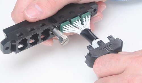
Amphenol LMD-LMS Modular Connectors

NO NEED FOR EXPENSIVE PC BOARDS AND HARDWARE
LMD/LMS Modular Connectors were designed by Amphenol Pyle-National to provide flexibility in the assembly of wire harnesses that are used in instrumentation and avionic control environments. The design of the LMD Modular Connectors provides a rack and panel or cable to cable attachment. LMS Modular Connectors allow an in-line splice using the same modules.
|
FEATURESAMPHENOL LMD-LMS MODULAR CONNECTORS - FEATURES
Design Features of LMD Connectors
LMD Features and Options LMD’s module options provide a mix of both active and passive devices within one connector. The features and options of this series describe the design flexibility in this connector series:
MATERIALS & FINISHESAMPHENOL LMD-LMS MODULAR CONNECTORS - MATERIALS & FINISHES
Housing Thermoplastic
Module Thermoplastic UL94VO
Module Seals Silicone
Contacts Copper Alloy
Plating 50 microinches Gold Plate
ELECTRICAL DATAAMPHENOL LMD-LMS MODULAR CONNECTORS - ELECTRICAL DATA
Contact Data Contact Size Wire Size Test Current (Amperes) Dielectric Withstanding Voltage AC (RMS) Max. Recommended Working Voltage AC (RMS) 22 22 5.0 1800 600 20 20 7.5 1800 600 16 16 13.0 2300 900 8* 12 23.0 2300 900 8 8 46.0 2300 900 Contact Size Wire Size Contact Crimp Tensile Strength Lbs. Min.
28 3
24 8
20 20 8* 14 70 8 10 150 * with #12 wire well MECHANICALAMPHENOL LMD-LMS MODULAR CONNECTORS - MECHANICAL
Temperature Rating –55° C to +140° C (-67 ° F to + 284° F)
Insulation Resistance (min.) 5000 megohms initial: 1000 megohms after 96 hours humidity
Durability 250 cycles (mating and unmating)
Vibration Maximum discontinuity of one microsecond when subjected to sinusoidal vibration of 10 to 2000 Hz at 15 gravity units
Physical Shock Maximum discontinuity of one microsecond when subjected to 1/2 -sine-wave transient shock of 50 gravity units with pulse duration of 11 milliseconds
Module Insertion & Removal Force 5 lbs. maximum
Module Retention 70 lbs. minimum
|
|
AMPHENOL LMD-LMS MODULAR CONNECTORS - APPLICATIONS
|
|
STEP 1: SHELL STYLEAMPHENOL LMD-LMS MODULAR CONNECTORS - PART NUMBER EXAMPLE
1 2 3 LMD-06 P J 4 PREFIX SHELL STYLE COUPLING MECHANISM ALTERNATE KEYING STEP 1: SELECT SHELL STYLE, PLUG OR RECEPTACLE
P R STEP 2: COUPLING MECHANISMSTEP 2: SELECT COUPLING MECHANISM

E - No Coupling Mechanism STEP 3: ALTERNATE KEYINGSTEP 3: SELECT ALTERNATE KEYING

1 2 3 4 5 6 7 8 EXAMPLE OF MATING HOUSINGS: LMD-06PJ4 mates to LMD-06RK4 MODULESAMPHENOL LMD-LMS MODULAR CONNECTORS - MODULES FOR CRIMP CONTACTS
No. of Contacts Contact Size Pin Socket
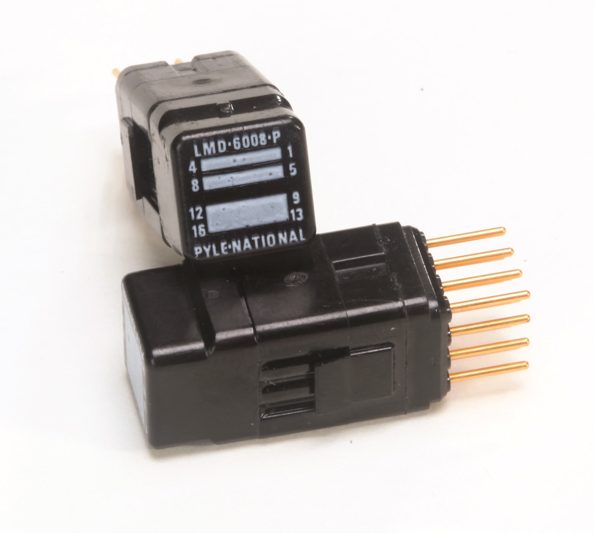
* Sealed version Sealed size 8 module N/A AMPHENOL LMD-LMS MODULE CONNECTORS - MODULES FOR BUSSING Bussing Circuit Contact Size Standard Module Sealed Module 3 20 LMD-6001-P LMD-6101-P 2 20 LMD-6002-P LMD-6102-P 1 20 LMD-6003-P LMD-6103-P 4 22 LMD-6004-P LMD-6104-P 2 22 LMD-6005-P LMD-6105-P 1 22 LMD-6006-P LMD-6106-P 1 16 LMD-6007-P LMD-6107-P 3 22 LMD-6008-P LMD-6108-P 3 20 LMD-6009-P LMD-6109-P Bussing Circuit For Size 22 Contacts 
Bussing Circuit For Size 20 Contacts 
Bussing Circuit For Size 16 Contacts 
AMPHENOL LMD-LMS MODULE CONNECTORS - MODULES WITH DIODES
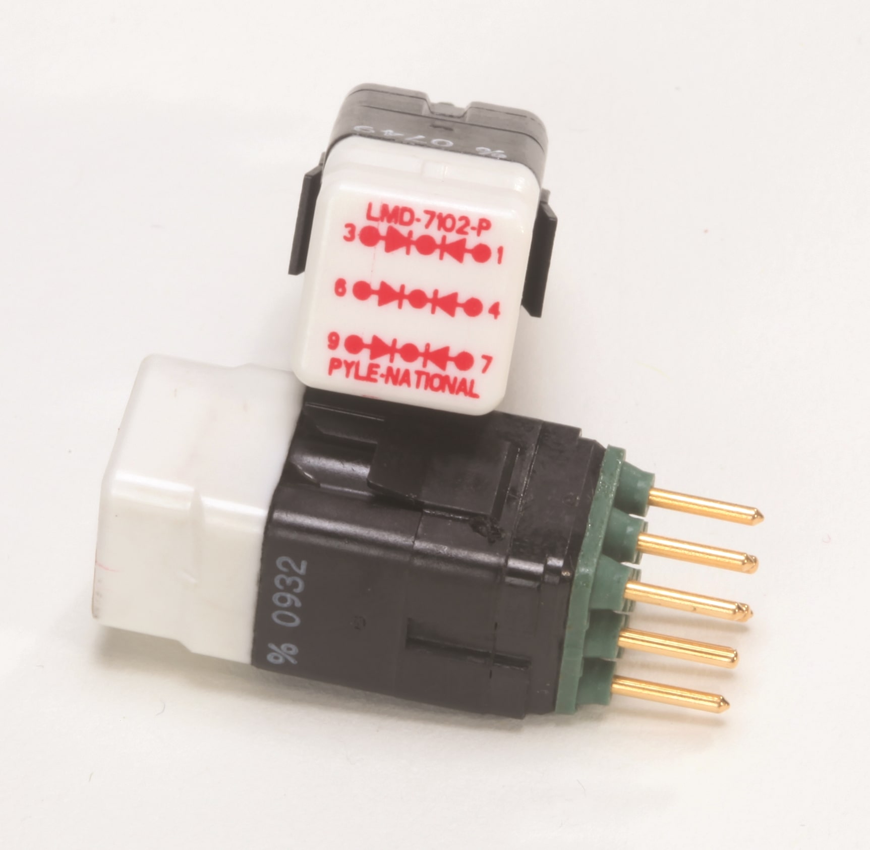
Size Contact LMD Diode Module Description 22 LMD-7111-P 8 discrete diodes 22 LMD-7112-P 4 pairs of diodes, each pair with a common cathode 22 LMD-7113-P 8 diodes with common cathode (pin #1) 20 LMD-7101-P 4 discrete wires 20 LMD-7102-P 3 pairs of diodes, each pair with common cathode 20 LMD-7103-P 8 diodes with common cathode (pin #5) Diode Modules For Size 22 Contacts 
Diode Modules For Size 20 Contacts 
AMPHENOL LMD-LMS MODULE CONNECTORS - MODULES WITH RELAYS
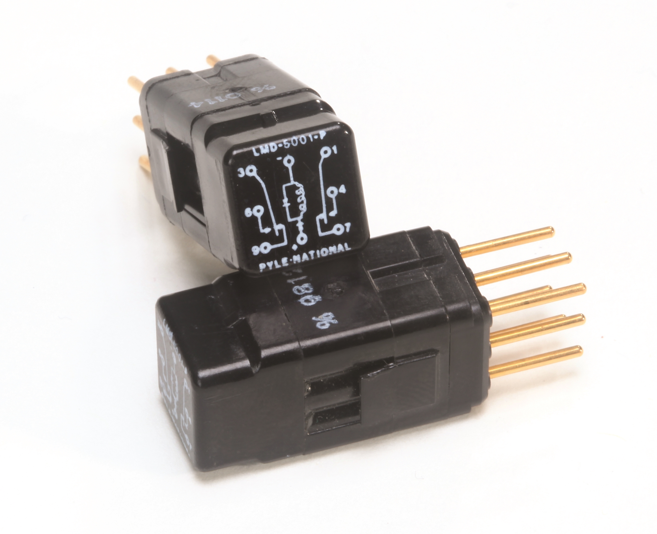
Relay Module Standard Module Sealed Module LMD-5001-P LMD-5101-P Relay Modules For Size 22 Contacts 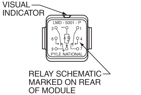
|
|
CONTACTSAMPHENOL LMD-LMS MODULAR CONNECTORS - CONTACTS
Contacts Size Wire Size AWG Pin Socket Wire Strip Lengths Wire Range Max. 22 22, 24, 26, 28 LMD-4022-36LJ LMD-4122-96LD 0.156-0.125 0.054 (1.37)
LMD-4020-96LD LMD-4020-10(*) LMD-4120-96LD LMD-4116-10(*) 0.185-0.155
LMD-4016-96LD LMD-4016-10(*) LMD-4116-96LD LMD-4116-10(*) 0.260-0.230
8 10, 8 LMD-4008-36L LMD-4108-36L 0.395-0.365 0.255 (6.48) (*) = Thermocouple Plating P = Chromel R = Alumel N = Constantan C = Copper CONTACT TOOLSAMPHENOL LMD-LMS MODULAR CONNECTORS - CONTACT TOOLS
Size Wire Size (AWG) Crimp Tool Positioner/ Positioner/ Insertion/ Insertion Extraction 22 22, 24, 26, 28 M22520/2-01 K703 M22520/2-07 M81969/14-01 Green White 20 20, 22, 24 M22520/1-01 M22520/1-02 M81969/14-02 Red White 16 16, 18, 20 M22520/1-01 M22520/1-02 M81969/14-03 Blue White 8 10, 8 TP-201393 TP-201408 M81969/14-06 - Red Module Extraction Tool: 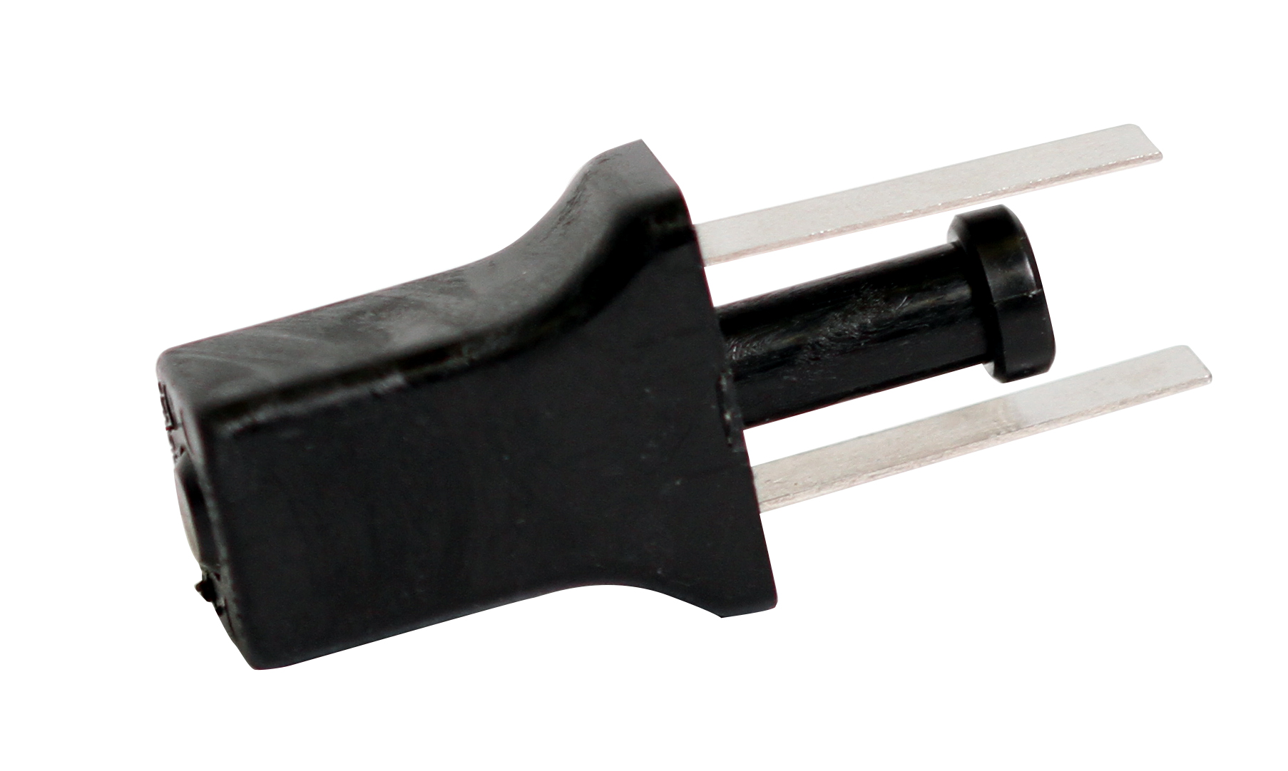 TP-201397 |
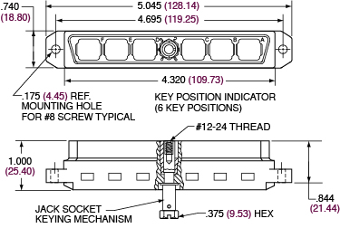
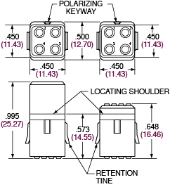
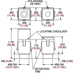
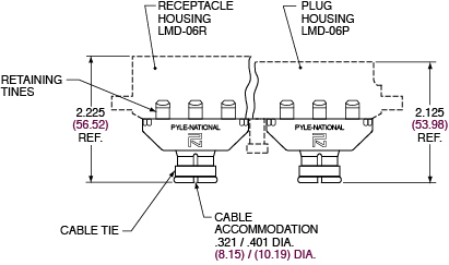
HOUSINGSAMPHENOL LMD-LMS MODULAR CONNECTORS - DIMENSIONS FOR LMD HOUSINGS Receptacle Housing 6 Bay Plug Housing 6 Bay MODULESAMPHENOL LMD-LMS MODULAR CONNECTORS - DIMENSIONS FOR LMD-LMS MODULES Modules with 16 Size 22 Contacts
Socket Module Pin Module Sealed Socket Module Sealed Pin Module Modules with 9 Size 20 Contacts
Socket Module Pin Module Sealed Socket Module Sealed Pin Module Modules with 4 Size 16 Contacts
Socket Module Pin Module Sealed Socket Module Sealed Pin Module Modules with 1 Size 8 Contact
Socket Module Pin Module BUSSING MODULESAMPHENOL LMD-LMS MODULAR CONNECTORS - DIMENSIONS FOR LMD-LMS BUSSING MODULES
Modules with Size 22 Contacts
Modules with Size 20 Contacts
Modules with Size 16 Contacts
Module Side View Standard Bussing Module
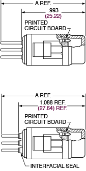
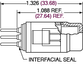
Sealed Bussing Module Contact Front View Bussing Configuration (Rear View) LMD Bussing Module Part Number Standard Module Sealed Module Contact Size Bussing Circuits A. Ref. LMD-6001-P LMD-6101-P 20 3 1.326 LMD-6002-P LMD-6102-P 20 2 1.326 LMD-6003-P LMD-6103-P 20 1 1.326 LMD-6004-P LMD-6104-P 22 4 1.256 LMD-6005-P LMD-6105-P 22 2 1.256 LMD-6006-P LMD-6106-P 22 1 1.256 LMD-6007-P LMD-6107-P 16 1 1.326 LMD-6008-P LMD-6108-P 22 3 1.326 LMD-6009-P LMD-6109-P 20 3 1.326 DIODE & RELAY MODULESAMPHENOL LMD-LMS MODULAR CONNECTORS - DIMENSIONS FOR LMD-LMS DIODE MODULES
Diode Modules with Size 22 Contacts
Contact Front View Module Side View Diode Configuration (Rear View) Diode Modules with Size 20 Contacts
Contact Front View Module Side View Diode Configuration (Rear View) LMD Diode Module Part Number Contact Size Circuit Description LMD-7111-P 22 8 discrete diodes LMD-7112-P 22 4 pairs of diodes, each pair with common cathode LMD-7113-P 22 8 diodes with common cathode (pin #1) LMD-7101-P 20 4 discrete diodes LMD-7102-P 20 3 pair of diodes, each pair with common cathode LMD-7103-P 20 8 diodes with common cathode (pin #5) AMPHENOL LMD-LMS MODULAR CONNECTORS - DIMENSIONS FOR LMD-LMS RELAY MODULES
Relay Modules with Size 20 Contacts LMD Relay Module Part Number Standard Module Sealed Module LMD-5001-P LMD-5101-P Contact Front View Module Side View Relay Configuration (Rear View) Standard
Sealed
ACCESSORIESAMPHENOL LMD-LMS MODULAR CONNECTORS - DIMENSIONS FOR ACCESSORIES
Strain Relief 2 Piece
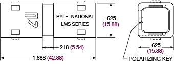
LMS In-Splice Housing
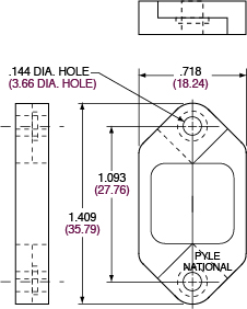
LMS Panel Mounting Bracket
CONTACTSAMPHENOL LMD-LMS MODULAR CONNECTORS - DIMENSIONS FOR LMD-LMS PIN CONTACTS
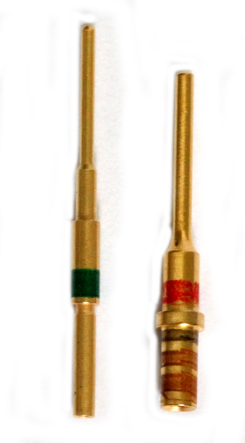
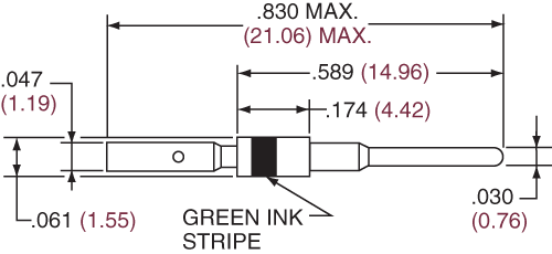
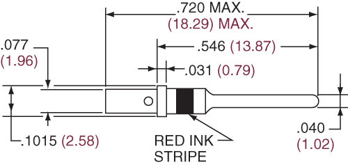
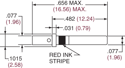
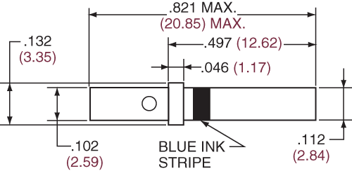
Pin Contact Size 22 - LMD-4022-36LJ
Pin Contact Size 20 - LMD-4020-96LD & LMD-4020-10 Types
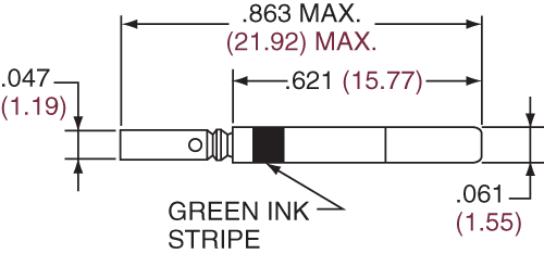
Pin Contact Size 16 - LMD-4016-96LD & LMD-4016-10 Types
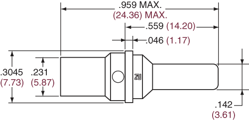
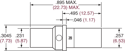
Pin Contact Size 8 - LMD-4008-36L
AMPHENOL LMD-LMS MODULAR CONNECTORS - DIMENSIONS FOR LMD-LMS SOCKET CONTACTS
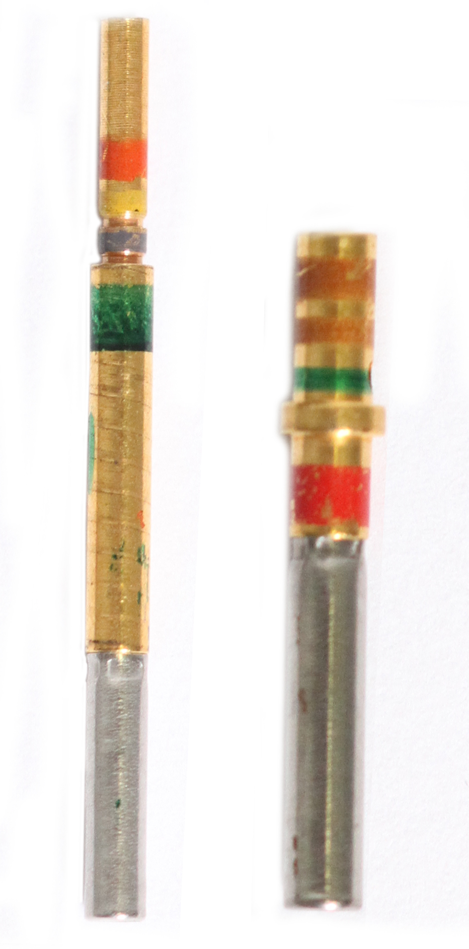
Socket Contact Size 22 - LMD-4122-96LD
Socket Contact Size 20 - LMD-4120-96LD & LMD-4120-10 Types
Socket Contact Size 16 - LMD-4116-96LD & LMD-4116-10 Types
Socket Contact Size 8 - LMD-4108-36L
|
|
CONTACTSAMPHENOL LMD-LMS MODULAR CONNECTORS - CRIMPING, INSERTION, & REMOVAL OF CONTACTS
Amphenol recommends the tools listed on the Contacts & Tooling Section for use with LMD connectors, and also the following procedures for wire preparation, crimping of wire and contact insertion and removal. Wire Preparation 
Strip wires to dimension “A” shown in table. Avoid cutting or nicking wire strands. Contact Size Wire Size Sealing Range Stripping Length Dimension "A" 22 20, 24, 26, 28 AWG 0.054 (1.37) 0.156-0.125 20 20, 22, 24 AWG 0.083 (2.11) 0.185-0.155 16 16, 18, 20 AWG 0.103 (2.61) 0.260-0.230 8 8, 10 AWG 0.255 (6.48) 0.395-0.35 Crimping Wire to Contacts
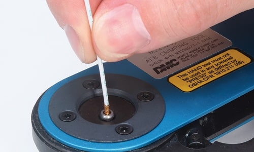
STEP 1: Fully insert wire into contact crimp pocket. Wire must be visible through wire inspection hole. STEP 2: Insert contact into tool (use proper crimping tool as listed in Contacts & Tooling). Crimp contact to wire. Tool will not open if contact is not fully crimped. STEP 3: After crimping, wire should be visible through wire inspection hole. Contact Insertion
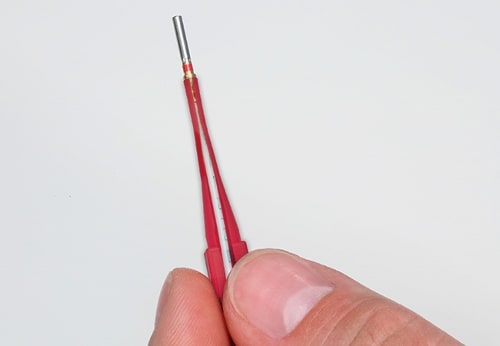
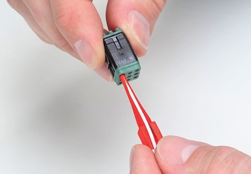
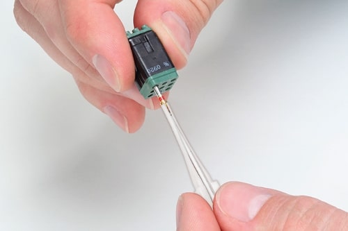
STEP 1: Using proper insertion/removal tool as listed on previous page, slip wire into insertion end (colored end), placing crimp end of contact inside the slotted portion and contact shoulder against end of tool. STEP 2: Align contact with the cavity at the rear face of the module. Carefully push the contact into the full depth of the cavity. Withdraw tool. A slight axial pull on the wire will confirm contact is locked in proper position. Contact Removal
MODULE & STRAIN RELIEFAMPHENOL LMD-LMS MODULE CONNECTOR - MODULE INSERTION/REMOVAL & USE OF STRAIN RELIEF
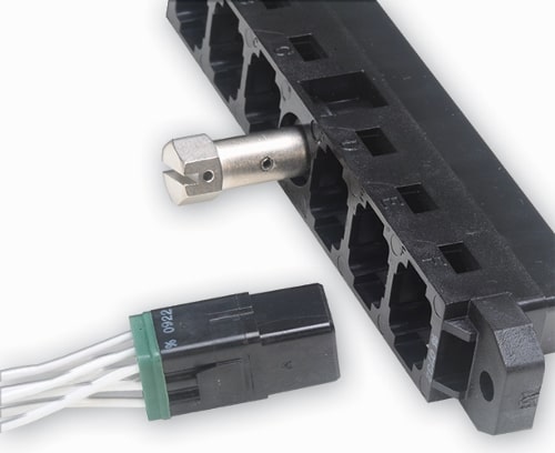
Pin or socket modules, wired or unwired, can be inserted or intermixed in plug or receptacle housings. Select from standard module configurations shown on pages 103 & 104, or select the optional bussing, diode or relay modules offered, shown on pages 105 & 106. The next instructions illustrate the proper method of insertion and removal of modules within the LMD connector. Module Insertion
Module Removal
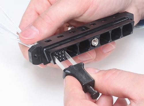
STEP 1: Select module to be removed and place the blades of removal tool into the removal slots at the front of the connector. Push the removal tool into the full depth of the cavity, releasing the module retention tines. STEP 2:With the module removal tool fully inserted, push the extraction plunger to eject the module out of the rear of the connector. Assembly of Internal Strain Relief Strain reliefs, if required, may be assembled to plug or receptacle connectors which have a full complement of modules installed. The following is instruction for assembling the internal attachment strain relief, part number LMD-5300-10A (see page 107).
Tape wire bundle in area of cable clamp, and build up diameter to approx. 3/8 inches, if required. Align self-locking tines of the strain relief housing with the cavities adjacent to each module. Push the strain relief housing into place until the self-locking tines snap and lock strain relief into position. Assemble opposite half of strain relief housing to connector and tighten tie-strap to provide clamping force on the wire bundle. Opening Strain Relief to Service Modules and Contacts
Internal attachment strain reliefs may be opened to provide module and/or contact accessibility. To service connectors, first cut and discard tie-strap on strain relief. Open strain relief halves approx. 45° each by bending along integral flexible hinge. After servicing, close strain relief halves and install and tighten new tie-strap. To completely remove strain relief from the housing in order to provide module access; first remove tie-strap, open strain relief halves 45° each, then remove module, then remove strain relief. |
Philadelphia
19116
Click here for the contact information of the branch nearest you.


