Anderson Power Products 3 Position Mini PL SPEC Pak® (16 To 22 Amps)
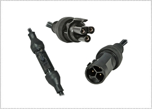
3 POSITION MINI PL SPEC PAK®
(16 TO 22 AMPS)
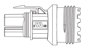
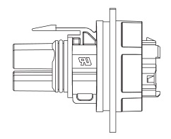
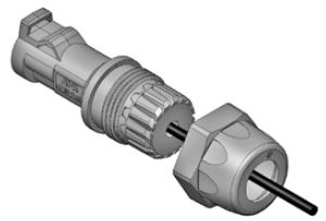
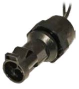
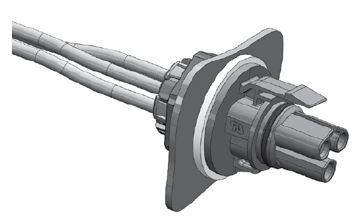
Anderson Power Products new SPEC Pak® Mini PL 3 position connector is a small, IP68 sealed interconnect solution that provides up to 3 contacts and is UL rated to carry up to 22 amps per contact at 600 volts. This connector is ideal for applications requiring power or power and signal combined in a compact environmentally sealed (IP68) package. Contacts are available for wires ranging from 24 AWG to 12 AWG. Contacts are 30μ gold plated to provide low resistance and up to 500 mating cycles. The male contacts are also available in 3 lengths to enable sequencing as required. The connectors meet the UL1977 Sec 10.2 touch safe requirements and have a manual release latch to prevent accidental un-mating.
The SPEC Pak® Mini PL 3 connectors are manufactured of durable polycarbonate material and meet UL94 V-0 flame resistance requirements.
|
FEATURESANDERSON POWER PRODUCTS 3 POLE MINI PL SPEC PAK® FEATURES
MATERIALS & FINISHESANDERSON POWER PRODUCTS 3 POLE MINI PL SPEC PAK® MATERIALS & FINISHES
Shell PC
Latch PC
Flammability UL 94 V-0
Weatherability UL764C / 12 mm, F1
Socket Body Copper Alloy, 200μ inch Sn over Ni
Socket Contact Copper Alloy, 30μ inch Au over Ni
Pin Copper Alloy, 300μ inch Au over Ni
NOTE: Sn = Tin Ni = Nickel Au = Gold ELECTRICAL DATAANDERSON POWER PRODUCTS 3 POLE MINI PL SPEC PAK® ELECTRICAL DATA
Current Rating (Amperes) UL 1977: 22
CSA (30°C Rise): 16 Voltage Rating UL 1977 (AC/DC): 600
Dielectric Withstanding (AC) 2200
Contact Resistance (average) 3 Milliohms
 File No. E26226 File No. E26226 CSA Certified File No. LR25154 CSA Certified File No. LR25154
MECHANICALANDERSON POWER PRODUCTS 3 POLE MINI PL SPEC PAK® MECHANICAL
Environmental Seal IEC: IP68
UL: 50E Wire Size 24 to 12 AWG
0.5 to 2.5 mm2 Sealing Options Sealing Gland
Operating Temperature -20 to 105°C
-4 to 221°F Mating Cycles (no load) 500
Contact Retention Force 10 lbf
44 N Mating Force (nominal) 5 lb
22 N Touch Safe (UL 1977 Sec. 10.2) Pass
Latch Strength (nominal) 24 lb
107 N |
|
ANDERSON POWER PRODUCTS 3 POLE MINI PL SPEC PAK® APPLICATIONS
|
|
STEP 1: SHELLANDERSON POWER PRODUCTS 3 POLE MINI PL SPEC PAK® PART NUMBER EXAMPLE 1 2-1 2-2 3 S K 1 -019 M03 PS 01 -P46 SERIES COLOR SHELL STYLE SHELL SIZE INSERT WIRE PROTECTION HOUSING & CONTACTS ARRANGEMENT EXPLANATION STEP 1 - SELECT SHELL 1 = Male, Receptacle (Pins) STEP 2-1 - SELECT SEALING GLAND 00 = No Wire Protection STEP 2-2 - SELECT SEALING GLAND 00 = No Wire Protection STEP 3 - SELECT CONTACT P46 = 20 - 24 AWG Pin STEP 1: SELECT SHELL
SPEC Pak® Shell KitsMinimum Quantity - 25 (sealing glands & contacts sold separately) Description Part Numbers Male, Receptacle Shell SK1-019M03 Female, Plug SK6-019M03 Female, Jam Nut SK7-019M03 Female, Cover SK9F-019 Male, Cover SK9M-019
STEP 2: SEALING GLANDSTEP 2: SELECT SEALING GLAND
FAQ
Q: Do I need a sealing gland?
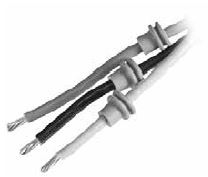
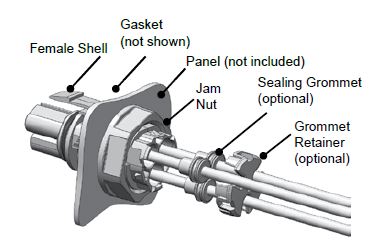
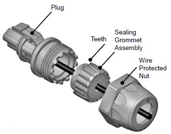
A: For IP68 rating, sealing glands are required with SK1-019M03 & SK6-019M03. A: For splash resistance in the unmated condition, use optional wire sealing grommets with SK7-019M03. (See Accessories) Q: How do I select the appropriate sealing gland? A: Identify the number of wires that will be used. Identify the outer diameter (OD) of those wire(s). 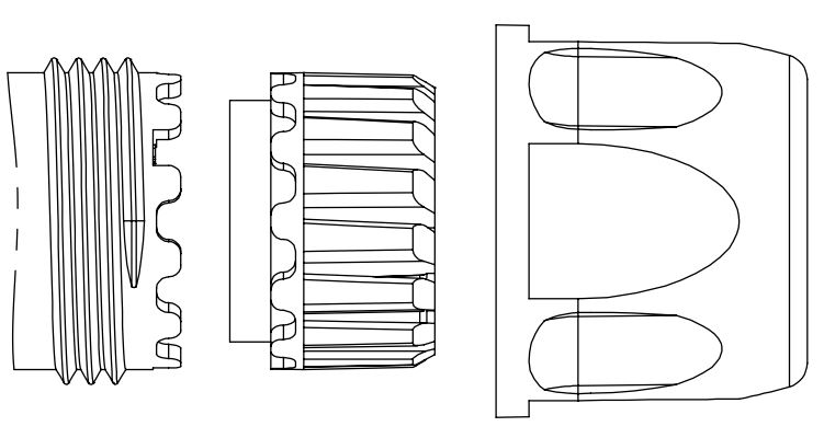 Material
Shell - PC
Sealing Grommet - EPDM
Flammability - UL94 V0
Color - Black
Torque Requirements
Hand tighten until snug, using a wrench tighten an additional 1/4 to 1/2 turn.
Wrench Size - 22
Operating Temperature
-20° to 105°C
-4° to 221°F
Bundled Cable Number of Wires Cable Range Wire Part Numbers Minimum Quantity 25 Connector Kit Designation 1 3.0 to 4.5 (0.12 - 0.18) PS1T20-5X PS 01 1 4.5 to 6.5 (0.18 - 0.26) PS1T20-7X PS 02 1 6.5 to 8.5 (0.26 - 0.33) PS1T20-9X PS 03 1 8.5 to 10.0 (0.33 - 0.39) PS1T20-10X PS 04 1 10.0 to 11.5 (0.39 - 0.45) PS1T20-12X PS 05 Discrete Wires Number of Wires Cable Range Wire Part Numbers Minimum Quantity 25 Connector Kit Designation 2 0.75 to 1.50 (0.03 - 0.06) PS2T20-2X PM 21 2 1.50 to 2.60 (0.06 - 0.10) PS2T20-3X PM 22 3 0.75 to 1.50 (0.03 - 0.06) PS3T20-2X PM 31 3 1.60 to 2.60 (0.06 - 0.10) PS3T20-3X PM 32 STEP 3: CONTACTSSTEP 3: SELECT CONTACTS
FAQ
Q: What should I consider when selecting the contacts?
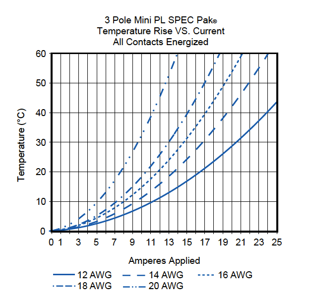
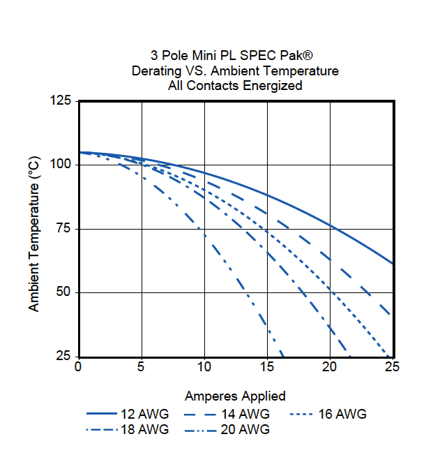
A: Determine the number of amps (continuous and peak). See temperature charts.
Q: What contacts are used in each shell?
A: Pins are used in SK1-019M03 (male receptacle).
Sockets are used in SK6-019M03 (female plug) & SK7-019M03 (female panel mount, jam nut)
Pin Contacts (PowerMod® Series) (For pre-mate and post-mate contacts for sequencing, contact us)
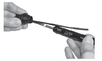
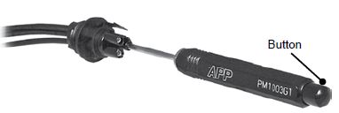
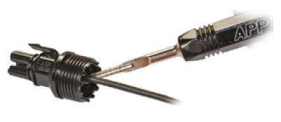
Standard Length 7.7 Type AWG mm² Part Numbers Part Numbers Connector Kit Designation Pin 24 to 20 0.25 to 0.50 PM16P2024S30 PM16P2024S30-50 P46 Pin 20 to 16 0.50 to 1.30 PM16P1620S30 PM16P1620S30-50 P45 Pin 16 to 14 1.30 to 2.10 PM16P1416S30 PM16P1416S30-50 P44 Pin 12 2.5 PM16P12S30 PM16P12S30-50 P47 Pneumatic Tool Hand Tool Tool Die Locator Insertion Tool Extraction Tool PM1000G1 TM0001 N/A TL0001 PM1002G1 PM1003G1 Socket Contacts (PowerMod® Series)
Standard Length 7.7 Type AWG mm² Part Numbers Part Numbers Connector Kit Designation Socket 24 to 20 0.25 to 0.50 PM16S2024S32 PM16S2024S32-50 S46 Socket 20 to 16 0.50 to 1.30 PM16S1620S32 PM16S1620S32-50 S45 Socket 16 to 14 1.30 to 2.10 PM16S1416S32 PM16S1416S32-50 S44 Socket 12 2.5 PM16S12S32 PM16S12S32-50 S47 Pneumatic Tool Hand Tool Tool Die Locator Insertion Tool Extraction Tool PM1000G1 TM0001 N/A TL0002 PM1002G1 PM1003G1 NOTE: APP tooling is required for UL & CSA compliance. Use of unapproved tools will void the connectors warranty. |
|
ANDERSON POWER PRODUCTS 3 POLE MINI PL SPEC PAK® CONTACTS & TOOLING
Pin Contacts (PowerMod® Series) (For pre-mate and post-mate contacts for sequencing, contact us)
Standard Length 7.7 Type AWG mm² Part Numbers Part Numbers Connector Kit Designation Pin 24 to 20 0.25 to 0.50 PM16P2024S30 PM16P2024S30-50 P46 Pin 20 to 16 0.50 to 1.30 PM16P1620S30 PM16P1620S30-50 P45 Pin 16 to 14 1.30 to 2.10 PM16P1416S30 PM16P1416S30-50 P44 Pin 12 2.5 PM16P12S30 PM16P12S30-50 P47 Pneumatic Tool Hand Tool Tool Die Locator Insertion Tool Extraction Tool PM1000G1 TM0001 N/A TL0001 PM1002G1 PM1003G1 Socket Contacts (PowerMod® Series)
Standard Length 7.7 Type AWG mm² Part Numbers Part Numbers Connector Kit Designation Socket 24 to 20 0.25 to 0.50 PM16S2024S32 PM16S2024S32-50 S46 Socket 20 to 16 0.50 to 1.30 PM16S1620S32 PM16S1620S32-50 S45 Socket 16 to 14 1.30 to 2.10 PM16S1416S32 PM16S1416S32-50 S44 Socket 12 2.5 PM16S12S32 PM16S12S32-50 S47 Pneumatic Tool Hand Tool Tool Die Locator Insertion Tool Extraction Tool PM1000G1 TM0001 N/A TL0002 PM1002G1 PM1003G1 NOTE: APP tooling is required for UL & CSA compliance. Use of unapproved tools will void the connectors warranty. |
|
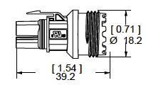
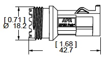
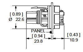
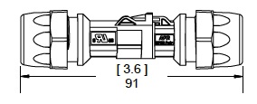
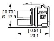
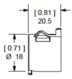
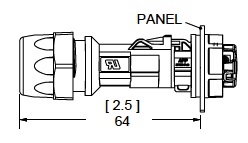
ANDERSON POWER PRODUCTS 3 POLE MINI PL SPEC PAK® DIMENSIONS Male Receptacle Female Plug Female Panel Mount SK1-019M03 & SK6-019M03 (mated) Male Cover Female Cover SK1-019M03 & SK7-019M03 (mated) |
|
ANDERSON POWER PRODUCTS 3 POLE MINI PL SPEC PAK® ACCESSORIES Wire Seal Accessories for use with SK7-021M03 Description Part Numbers Part Numbers Wire Seal Retainer 2-8702P1 - Grommet, wire range 1.2 - 1.9mm (0.047" - 0.075") OD, Orange 114916P1 114916P1-50 Grommet, wire range 1.9 - 2.4mm (0.075" - 0.090") OD, Yellow 114916P2 114916P2-50 Grommet, wire range 2.5 - 3.2mm (0.100" - 0.130") OD, Tan 114916P3 114916P3-50 Sealing Plug 114916P4 114916P4-50 Covers Description Part Numbers Female Cover SK9F-019 Male Cover SK9M-019 |
|
ANDERSON POWER PRODUCTS 3 POLE MINI PL SPEC PAK® TOOLING PDFS
|
|
INLINE RECEPTACLEANDERSON POWER PRODUCTS 3 POLE MINI PL SPEC PAK® INLINE RECEPTACLE ASSEMBLY
Tools & supplies you will need:
STEP 1 - WIRE PROTECTION:
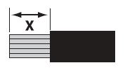
STEP 2 - PREPARE WIRES: Strip individual wire taking care not to damage the copper conductor. Crimp Barrel ID Wire Gauge In. (mm) X Inches (mm) For more details, see document 1S6420 #24 / 20 #20 / 16 #16 / 14 #12 0.04 (1.1) 0.07 (1.7) 0.08 (2.1) 1.10 (2.6) Wire Insulation OD < crimp barrel ID x = 0.21” (5.5mm) Wire Insulation OD > crimp barrel ID x = 0.28” (7.0mm)
STEP 3 - CRIMP CONTACTS: Crimp contacts per crimp tool instructions. WARNING: APP tooling is required for UL and CSA compliance. Use of unapproved tooling will void the connector warranty. PM16P2024S30 PM16P1620S30 PM16P1416S30 PM16P12S30 24 – 20 AWG 0.25 – 0.50 mm2 20 – 16 AWG 0.50 – 1.30 mm2 16 – 14 AWG 1.30 – 2.10 mm2 12 AWG 3.30 mm2
STEP 4 - POPULATE SHELL:
B. Repeat Step 4a as necessary.
Figure 3 Assembly Complete STEP 5 - FINAL ASSEMBLY: JAM NUT-FEMALEANDERSON POWER PRODUCTS 3 POLE MINI PL SPEC PAK® JAM NUT (FEMALE) ASSEMBLY
Tools & supplies you will need:
STEP 1 - WIRE PROTECTION:
STEP 2 - PREPARE WIRES: Strip individual wire taking care not to damage the copper conductor. APP Contact Part Number X Inches X (mm) Instruction Sheet PM16S2024S32 PM16S1620S32 PM16S1416S32 PM16S12S32 Wire Insulation OD < crimp barrel ID x = 0.21” (5.5mm) Wire Insulation OD > crimp barrel ID x = 0.28” (7.0mm)
STEP 3 - CRIMP CONTACTS: Crimp contacts per crimp tool instructions. WARNING: APP tooling is required for UL and CSA compliance. Use of unapproved tooling will void the connector warranty. PM16S2024S32 PM16S1620S32 PM16S1416S32 PM16S12S32 24 – 20 AWG 0.25 – 0.50 mm2 20 – 16 AWG 0.50 – 1.30 mm2 16 – 14 AWG 1.30 – 2.10 mm2 12 AWG 3.30 mm2
STEP 4 - POPULATE SHELL:
B. Repeat Step 4a as necessary.
Figure 4 Figure 5 Assembly Complete STEP 5 - FINAL ASSEMBLY: PLUG-FEMALEANDERSON POWER PRODUCTS 3 POLE MINI PL SPEC PAK® PLUG (FEMALE) ASSEMBLY
Tools & supplies you will need:
STEP 1 - WIRE PROTECTION:
STEP 2 - PREPARE WIRES: Strip individual wire taking care not to damage the copper conductor. Crimp Barrel ID Wire Gauge In. (mm) X Inches (mm) For more details, see document 1S6420 #24 / 20 #20 / 16 #16 / 14 #12 0.04 (1.1) 0.07 (1.7) 0.08 (2.1) 1.10 (2.6) Wire Insulation OD Wire Insulation OD > crimp barrel ID x = 0.28” (7.0mm)
STEP 3 - CRIMP CONTACTS: Crimp contacts per crimp tool instructions. WARNING: APP tooling is required for UL and CSA compliance. Use of unapproved tooling will void the connector warranty. PM16S2024S32 PM16S1620S32 PM16S1416S32 PM16S12S32 24 – 20 AWG 0.25 – 0.50 mm2 20 – 16 AWG 0.50 – 1.30 mm2 16 – 14 AWG 1.30 – 2.10 mm2 12 AWG 3.30 mm2
STEP 4 - POPULATE SHELL:
B. Repeat Step 4a as necessary.
Figure 3 Assembly Complete STEP 5 - FINAL ASSEMBLY: |
ANDERSON POWER PRODUCTS 3 POLE MINI PL SPEC PAK® VIDEO
|
Philadelphia
19116
Click here for the contact information of the branch nearest you.


