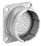
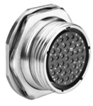
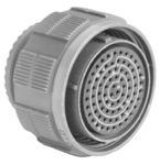
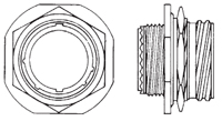
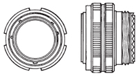
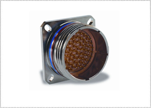
ITT Cannon KJB Series 38999-Style Series III Miniature Circular Connectors
INTERMATEABLE WITH ALL
38999-STYLE SERIES III CONNECTORS
ITT Cannon KJB 38999-Style Series III connectors offer high-density contact arrangements in a lightweight miniature circular connector. These 38999-Style connectors have quick-mating, triple-lead threaded, self-locking coupling for high-vibration applications, are environmentally sealed, and operate across a wide temperature range in extreme environments. They feature high density layouts with up to 128 data connections and power contacts rated up to 23A.
The ITT Cannon KJB series was originally designed for military vehicles and are now industry standard aerospace and military connectors. They are intermateable with Souriau connectors and all 38999-Style Series III connectors. For full product details on the KJB series 38999-Style Series III, please see the specifications below.
|
FEATURESITT CANNON KJB SERIES FEATURES
MATERIALS & FINISHESITT CANNON KJB SERIES MATERIALS & FINISHES
Shell Aluminum Alloy or Composite
Plating W - Olive Drab Chromate over Cadmium over Electroless Nickel per QQ-P-416
F - Electroless Nickel per QQ-N-290 J - Composite, Olive Drab over Cadmium over Electroless Nickel M - Composite, Electroless Nickel T69 -Green Zinc Cobalt A297 - Black Electroless Nickel A296 - Black Zinc Cobalt G - Space Grade Outgassed Contacts Copper alloy
Plating Gold plate, 50 microinches per MIL-G-45204 type II, grade C, class 1
Insulator Hard plastic wafer which contains metal retention tines for high-reliability retention of crimp contacts
Grommet & Seals Silicone-based elastomer
Grounding Springs Beryllium copper (grounded plug only)
ELECTRICAL DATAITT CANNON KJB SERIES ELECTRICAL DATA
Test Voltage (Unmated Conditions)Service Rating Test Voltages N M I II Sea Level 1000 1300 1800 2300 100,000 feet 200 200 200 200 Operating Voltage Service Rating N M I II Operating Voltage 300VAC/450VDC 400VAC/500VDC 600VAC/850VDC 900VAC/1250VDC Current Rating by contact size and wire accomodations (Test Amps) Wire Size 22D 20 16 12 28 1.5 - - - 26 2.0 - - - 24 3.0 3.0 - - 22 5.0 5.0 - - 20 - 7.5 7.5 - 18 - - 10.0 - 16 - - 13.0 - 14 - - - 17.0 12 - - - 23.0 Contact Resistance of mated contacts end-to-end Contact Size Maximum Millivolt Drop 22D 73 20 55 16 49 12 42 Insulation Resistance 5,000 megohms minimum
MECHANICALITT CANNON KJB SERIES MECHANICAL
Operating Temperature W, T69, A296, A297 plating -65° to 175°C (-87°F to 347°F)
F + G plating -65°C to 200°C (-85°F to 392°F) Sealing Against sand, dust per MIL-STD-202 & ice
Wire Sealing Range Contact Size Minimum (Inches) Maximum (Inches) Minimum (mm) Maximum (mm) 22D 0.03 0.054 0.76 1.37 20 0.040 0.083 1.02 2.11 16 0.065 0.109 1.65 2.77 12 0.097 0.142 2.46 3.61 8 0.135 0.155 3.43 3.74 Insulation Strip Length Contact Size Strip Length Inches (mm) 22D .125 (3.18) 20 .188 (4.77) 16 .188 (4.77) 12 .188 (4.77) Mating Life 500 cycles minimum
Salt Spray Finish W: 500-hour per MIL-STD-1344A method 1001 condition C
Finish F & G, T69, A296: 48-hour per MIL-STD-1344A method 1001 condition B Finish A297: 192 hour Finish J & M: 1000-hour per MIL-STD-1344A method 1001 condition C Temperature Durability Finish W, T69, A296, A297: 175°C (347°F), Finish F: 200°C (392°F), mated, wired test period 1000 hours to MIL-STD-1344 Method 1005
Chemical Resistance Lubricating oils, hydraulic fluids, coolants, deicing fluids per MIL-STD-1344A Method 1016 condition a - I
Sine Vibration 60 grms at -65°C to +200°C (-85°F to +392°F) ambient temperature with stimulated accessory load
Random Vibration 49.5 grms at ambient temperatures
Shock 300g
EMI Shielding Effectiveness 100 MHz to 10 GHz - minimum attenuation of 50 dB
Contact Type Crimp, fiber optic, co-ax, twinax, thermocouple or printed circuit
Number of Circuits 3 to 128
Contact Insertion Insertion from rear of connector with simple plastic or high-quality metal hand tool. Extraction from rear with simple plastic or high-quality metal hand tools.
Contact Retention Per MIL-DTL-38999 tested to MIL-STD-1344A method 2007
Contact Axial Load Newtons +/-10% Axial Load Pounds +/-10% 22D 44 10 20 67 15 16 112 25 12 111 25 NOTE: CT/CA/MS receptacle contacts are bonded into the insulator Polarization Five keyways with optional minor keyways rotation (Note insert and main keyway remain fixed)
|
|
ITT CANNON KJB SERIES APPLICATIONS
Military and Industrial environments requiring a miniature, high-density, environmental connector
|
|
STEP 1: STYLEITT CANNON KJB SERIES MILITARY PART NUMBER EXAMPLE
1 2 3 4 5 6 D38999/20 F A35 P N -LC SHELL STYLE PLATING LAYOUT CONTACT POLARIZATION MODIFIER ITT CANNON KJB SERIES COMMERCIAL PART NUMBER EXAMPLE
1 3A 2 3B 4 5 6 KJB0T 9 F 35 P N L SHELL STYLE LAYOUT 1st # PLATING LAYOUT 2nd # CONTACT POLARIZATION MODIFIER KJB = Plastic Retention Tines (White) KJA = Metal Retention Tines (Pink) Note: To develop KJB, Step 3 is divided into 3A and 3B. 3A (Shell size) precedes Step 2 (Plating Designation) followed by 3B, last part of layout # (Omit the dash) STEP 1: CHOOSE SHELL STYLE

STEP 2: PLATINGSTEP 2: CHOOSE PLATING

F = Electroless Nickel (RoHS) G = Space Grade Outgassed J = Composite, Olive Drab over M = Composite, Electroless Nickel W = Olive Drab Chromate over BLANK = If using commercial STEP 3: LAYOUTSTEP 3: CHOOSE LAYOUT
Military Commercial Contacts D3899 Layout KJA/KJB Service Rating Total 22D 20 16 12 8 A35 9-35 M 6 6 A98 9-98 I 3 3 B35 11-35 M 13 13 B5 11-5 I 5 5 B98 11-98 I 6 6 C35 13-35 M 22 22 C8 13-8 I 8 8 C98 13-98 I 10 10 D15 15-15 I 15 14 1 D18 15-18 I 18 18 D19 15-19 I 19 19 D35 15-35 M 37 37 D5 15-5 II 5 5 D97 15-97 I 12 8 4 E26 17-26 I 26 26 E35 17-35 M 55 55 E6 17-6 I 6 6 E8 17-8 II 8 8 F11 19-11 II 11 11 F32 19-32 I 32 32 F35 19-35 M 66 66 G11 21-11 M 11 11 G16 21-16 II 16 16 G35 21-35 M 79 79 G39 21-39 I 39 37 2 G41 21-41 I 41 41 G75 21-75 M 4 4** H21 23-21 II 21 21 H35 23-35 M 100 100 H53 23-53 I 53 53 H55 23-55 I 55 55 J19 25-19 I 19 19 - 25-20 I*** 30 10 13 4* 3** J24 25-24 I 24 12 12 J29 25-29 I 29 29 J35 25-35 M 128 128 - 25-37 I 37 37 J4 25-4 I 56 48 8 - 25-42 I 42 38 4* J43 25-43 I 43 23 20 - 25-46 I 46 40 4 2* J61 25-61 I 61 61 - 25-645 I 64 40 8 10 6 - 25-665 I 66 53 2 11 - 25-8 M*** 8 8*** S = Socket only * Coax ** Twinax *** Coax/Twinax NOTE: Coaxial type contacts are only rated for 175°C (347°F). Contact us for information Read Less LAYOUTS BY NUMBER OF CONTACTS
Drawing not to scale; mating face view of pin insert shown (socket view is opposite). Contacts 3 5 6
D38999 Layout A98 G75 B5 D5 B98 E6 A35 KJB Layout 9-98 21-75 11-5 15-5 11-98 17-6 9-35 # of Contacts 3-#20 4-#8 5-#20 5-#16 6-#20 6-#12 6-#22D Service Rating M M** I II I I M Contacts 8 10 11 12
D38999 Layout C8 E8 - C98 F11 G11 D97 KJB Layout 13-8 17-8 25-8 13-98 19-11 21-11 15-97 # of Contacts 8-#20 8-#16 8-#8*** 10-#20 11-#16 11-#12 8-#20; 4-#16 Service Rating I II Coax*** I II I I Contacts 13 15 16 18 19
D38999 Layout B35 D15 G16 D18 D19 J19 KJB Layout 11-35 15-15 21-16 15-18 15-19 25-19 # of Contacts 13-#22D 14-#20; 1-#16 16-#16 18-#20 19-#20 19-#12 Service Rating M I II I I I Contacts 21 22 24 26 29
D38999 Layout H21 C35 J24 E26 J29 KJB Layout 23-21 13-35 25-24 17-26 25-29 # of Contacts 21-#16 22-#22D 12-#16; 12-#12 26-#20 29-#16 Service Rating II M I I I Contacts 30 32 37 39
D38999 Layout - F32 D35 - G39 KJB Layout 25-20 19-32 15-35 25-37† 21-39 # of Contacts 10-#20; 13-#16; 4*#12; 3**#8 32-#20 37-#22D 37-#16 37-#20; 2-#16 Service Rating I*** I M I I Contacts 41 42 43 46 53
D38999 Layout G41 J42 J43 - H53 KJB Layout 21-41 25-42 2543 25-46 23-53 # of Contacts 41-#20 38-#20; 4*-#8 23-#20; 20-#16 40-#20; 4-#16; 2*#8 53-#20 Service Rating I I* I I* I Contacts 55 56 61 64
D38999 Layout E35 H55 J4 J61 - KJB Layout 17-35 23-55 25-4 25-61 25-64† # of Contacts 55-#22D 55-#20 48-#20; 8-#16 61-#20 40-#22D; 8-#20; 10-#16; 6-#12 Service Rating M I I I I Contacts 66 79 100 128
D38999 Layout F35 - G35 H35 J35 KJB Layout 19-35 25-66† 21-35 23-35 25-35 # of Contacts 66-#22D 53-#22D; 2-#20; 11-#16 79-#22D 100-#22D 128-#22D Service Rating M I M M M * Coax ** Twinax *** Coax/Twinax † Available in socket insert only NOTE: Coaxial type contacts are only rated for 175°C (347°F). Contact us for information. Read Less STEP 4: CONTACTSTEP 4: CHOOSE CONTACT
See step 6 if you are not ordering contacts with part 
P = Pin A = Less Pin Contacts STEP 5: ROTATIONSTEP 5: CHOOSE ROTATION

N = Normal Standard (omit on Military part number)
C = Check for Availability Minor Key Locations Shell Size AR & AP BR & BP CR & CP DR & DP 9 N 105 140 215 265 9 A 102 132 248 320 9 B 80 118 230 312 9 C 35 140 205 275 9 D 64 155 234 304 9 E 91 131 197 240 11 N 95 141 208 236 13 A 113 156 182 292 15 B 90 145 195 252 15 C 53 156 220 255 15 D 119 146 176 298 15 E 51 141 184 242 17 N 80 142 196 293 19 A 135 170 200 310 19 B 49 169 200 244 19 C 66 14o 200 257 19 D 62 145 180 280 19 E 79 153 197 272 21 N 80 142 196 293 23 A 135 170 200 310 25 B 49 169 200 244 25 C 66 140 200 257 25 D 62 145 180 280 25 E 79 153 197 272 Receptacle Plug STEP 6: MODIFIERSTEP 6: CHOOSE MODIFIER
-LC = For use with standard contacts, but supplied without contacts, seal plugs or tools -A296 = Black Zinc Cobalt -L = Supplied without contacts, seal plugs or tools -16 = Outgassed NASA Space Grade -27 = Outgassed Standrad Connector Note: L/C is not marked on part For other commercial modification, i.e., less tools, with PC contact or with endbell, contact us. |
CONTACTSITT CANNON KJB SERIES CONTACTS - PINS
Color Bands Wire Range Contact Wire Size Pin Contact 1 2 3 Wire Strip Min. Max. Wire Hole Filler Color 22D 22, 24, 26 & 28 M39029/58-360 Orange Blue Black .125 (3.18) .030 (0.76) .054 (1.37) MS27488-22-2 Black 20 20, 22, & 24 M39029/58-363 Orange Blue Orange .188 (4.77) .040 (1.02) .083 (2.11) MS27488-20-2 Red 16 16, 18 & 20 M39029/58-364 Orange Blue Yellow .188 (4.77) .065 (1.65) .109 (2.77) MS27488-16-2 Blue 12 12 & 14 M39029/58-365 Orange Blue Green .188 (4.77) .097 (2.46) .142 (3.61) MS27488-12-2 Yellow 8 Co-ax* - - - - .135 (3.43) .155 (3.94) MS27488-8-2 - For Printed Circuit, Fiber Optic (MIL-T-29504/4 for size 16 contacts) or Thermocouple, contact us. ITT CANNON KJB SERIES CONTACTS - SOCKETS
Color Bands Wire Range Contact Wire Size Socket Contact 1 2 3 Wire Strip Min. Max. Wire Hole Filler Color 22D 22, 24, 26 & 28 M39029/56-348 Orange Yellow Gray .125 (3.18) .030 (0.76) .054 (1.37) MS27488-22-2 Black 20 20, 22, & 24 M39029/56-351 Orange Green Brown .188 (4.77) .040 (1.02) .083 (2.11) MS27488-20-2 Red 16 16, 18 & 20 M39029/58-352 Orange Green Red .188 (4.77) .065 (1.65) .109 (2.77) MS27488-16-2 Blue 12 12 & 14 M39029/56-353 Orange Green Orange .188 (4.77) .097 (2.46) .142 (3.61) MS27488-12-2 Yellow 8 Co-ax* - - - - .135 (3.43) .155 (3.94) MS27488-8-3 - For Printed Circuit, Fiber Optic (MIL-T-29504/5 for size 16 contacts) or Thermocouple Contacts, contact us. Contact Color Codes 0 Black 1 Brown 2 Red 3 Orange 4 Yellow 5 Green 6 Blue 7 Violet 8 Gray 9 White * Contact us for more information CONTACT TOOLSITT CANNON KJB SERIES CONTACT TOOLS - PINS
Contact Size Hand Crimp Tool Power Crimp Tool Turret Heads Use Locator Color Plastic Insertion/ Extraction Tool Insertion Tip Color Extraction Tip Color Metal Insertion Tool Color Band Metal Extraction Tool Color Band 1 Color Band 2 22D M22320/ 2-01 CBT565 M22520/ 2-09 - M81969/ 14-01 Green White MS27495 A22M Black MS27495 R22M Black White 20 M22320/ 1-01 CBT530 M22520/ 1-04 Red M81969/ 14-10 Red Orange MS27495 A20 Red MS27495 R20 Red White 16 M22320/ 1-01 CBT530 M22520/ 1-04 Blue M81969/ 14-03 Blue White MS27495 A16 Blue MS27495 R16 Blue White 12 M22320/ 1-01 CBT530 M22520/ 1-04 Yellow M81969/ 14-04 Yellow White DAK95- 12B - DRK95- 12B - - 8 - - - - - - - - - - - - ITT CANNON KJB SERIES CONTACT TOOLS - SOCKETS
Contact Size Hand Crimp Tool Power Crimp Tool Turret Heads Use Locator Color Plastic Insertion/ Extraction Tool Insertion Tip Color Extraction Tip Color Metal Insertion Tool Color Band Metal Extraction Tool Color Band 1 Color Band 2 22D M22320/ 2-01 CBT565 M22520/ 2-07 - M81969/ 14-01 Green White MS27495 A22M Black MS27495 R22M Black White 20 M22320/ 1-01 CBT530 M22520/ 1-04 Red M81969/ 14-10 Red Orange MS27495 A20 Red MS27495 R20 Red White 16 M22320/ 1-01 CBT530 M22520/ 1-04 Blue M81969/ 14-03 Blue White MS27495 A16 Blue MS27495 R16 Blue White 12 M22320/ 1-01 CBT530 M22520/ 1-04 Yellow M81969/ 14-04 Yellow White DAK95- 12B - DRK95- 12B - - 8 - - - - - - - - - - - - ITT CANNON KJB SERIES D38999-22 TOOL KIT / D38999-20 TOOL KIT CONTAINS:
Band #1 indicates Tool Size Band #2 indicates Removal Tool |
WALL MOUNT RECEPTACLEITT CANNON KJB SERIES WALL MOUNT RECEPTACLE
D38999/20
Shell Size D38999/ 20 KJB0 Overall Length A Max. Front Flange to Mating Face B +1.4/0.0 Rear Metric Thread (Plated) C Mating Thread Class 2A (Plated) D Flange Thick- Flange Outer Hole G1 Outer Hole G2 T TT A 9 31.5 19.5 M12x1.0-6g 0.100R 5/8-.1P-.3L-TS 2.5 23.8 18.26 15.09 3.25 5.49 B 11 31.5 19.5 M15x1.0-6g 0.100R 3/4-.1P-.3L-TS 2.5 26.2 20.62 18.26 3.25 4.93 C 13 31.5 19.5 M18x1.0-6g 0.100R 7/8-.1P-.3L-TS 2.5 28.6 23.01 20.62 3.25 4.93 D 15 31.5 19.5 M22x1.0-6g 0.100R 1-.1P-.3L-TS 2.5 31.0 24.61 23.01 3.25 4.93 E 17 31.5 19.5 M25x1.0-6g 0.100R 1 3/16-.1P-.3L-TS 2.5 33.3 26.97 24.61 3.25 4.93 F 19 31.5 19.5 M28x1.0-6g 0.100R 1 1/4-.1P-.3L-TS 2.5 36.5 29.36 26.97 3.25 4.93 G 21 31.5 18.7 M31x1.0-6g 0.100R 1 3/8-.1P-.3L-TS 3.2 39.7 31.75 29.36 3.25 4.93 H 23 31.5 18.7 M34x1.0-6g 0.100R 1 1/2-.1P-.3L-TS 2.5 42.9 34.92 31.75 3.91 6.15 J 25 31.5 18.7 M37x1.0-6g 0.100R 1 5/8-.1P-.3L-TS 3.2 46.0 38.10 34.92 3.91 6.15 All dimensions in millimeters (except Mating Thread) JAM NUT RECEPTACLEITT CANNON KJB SERIES JAM NUT RECEPTACLE
D38999/24
Shell Size D38999/ 24 KJB7 Overall Length A Max. Front Flange to Mating Face B Max. Rear Metric Thread (Plated) C Mating Thread Class 2A (Plated) D Flange Thick- ness E +0.3-0.1 Jam Nut Thread R F +.1-.25 Flange Wrench Flas S +/- 0.4 A 9 31.57 22.12 M12x1-6g 0.100R 5/8-.1P-.3:-TS 2.64 M17x1-6g 0.100R 16.70 27.0 B 11 31.57 22.12 M15x1-6g 0.100R 3/4-.1P-.3:-TS 2.64 M20x1-6g 0.100R 17.07 31.8 C 13 31.57 22.3 M18x1-6g 0.100R 7/8-.1P-.3:-TS 2.64 M25x1-6g 0.100R 23.82 34.9 D 15 31.57 22.3 M22x1-6g 0.100R 1-.1P-.3:-TS 2.64 M28x1-6g 0.100R 27.0 38.1 E 17 31.57 22.3 M25x1-6g 0.100R 1 3/16-.1P-.3:-TS 2.64 M32x1-6g 0.100R 30.14 41.3 F 19 31.57 22.3 M28x1-6g 0.100R 1 1/4-.1P-.3:-TS 3.43 M35x1-6g 0.100R 33.32 46.0 G 21 31.57 22.3 M31x1-6g 0.100R 1 3/8-.1P-.3:-TS 3.43 M38x1-6g 0.100R 36.50 49.2 H 23 31.57 22.3 M34x1-6g 0.100R 1 1/2-.1P-.3:-TS 3.43 M41x1-6g 0.100R 38.67 52.4 J 25 31.57 22.3 M37x1-6g 0.100R 1 5/8-.1P-.3:-TS 3.43 M44x1-6g 0.100R 42.85 55.4 All dimensions in millimeters (except Mating Thread) STRAIGHT PLUG GROUNDEDITT CANNON KJB SERIES STRAIGHT PLUG GROUNDED
D38999/26
Shell Size D38999/ 26 KJB6 Overall Length A Max. B + .2-0 Rear Metric Thread (Plated) C Mating Thread Class 2B (Plated) D Overall Diameter E Max. F Max. W +.2/-.1 A 9 31.34 18.4 M12x1-6g 0.100R 5/8-.1P-.3L-TS 21.8 19.0 19.3 B 11 31.34 21.1 M15x1-6g 0.100R 3/4-.1P-.3L-TS 25.0 21.9 19.3 C 13 31.34 25.4 M18x1-6g 0.100R 7/8-.1P-.3L-TS 29.4 26.1 19.3 D 15 31.34 28.7 M22x1-6g 0.100R 1-.1P-.3L-TS 32.5 29.3 19.3 E 17 31.34 32.2 M25x1-6g 0.100R 1 3/16-.1P-.3L-TS 35.7 32.8 19.3 F 19 31.34 34.9 M28x1-6g 0.100R 1 1/4-.1P-.3L-TS 38.5 35.5 19.3 G 21 31.34 38.1 M31x1-6g 0.100R 1 3/8-.1P-.3L-TS 41.7 38.7 19.3 H 23 31.34 41.1 M34x1-6g 0.100R 1 1/2-.1P-.3L-TS 44.9 41.7 19.3 J 25 31.34 44.3 M37x1-6g 0.100R 1 5/8-.1P-.3L-TS 48.0 44.9 19.3 All dimensions in millimeters (except Mating Thread) PANEL CUTOUTSITT CANNON KJB SERIES WALL MOUNT RECEPTACLE
Shell Size D38999/20 & KJB0 Wall Mount D38999 KJA G1 G2 H Dia. +.005 (.130) Front Mount J Min. A 9 .719 (18.26) .594 (15.09) .134 (3.40) .626 (15.90) B 11 .812 (20.62) .719 (18.26) .134 (3.40) .751 (19.08) C 13 .906 (23.01) .812 (20.62) .134 (3.40) .876 (22.25) D 15 .969 (24.61) .906 (23.01) .134 (3.40) 1.001 (25.43) E 17 1.062 (26.97) .969 (24.61) .134 (3.40) 1.188 (30.18) F 19 1.156 (29.36) 1.062 (26.97) .134 (3.40) 1.251 (31.78) G 21 1.250 (31.75) 1.156 (29.36) .134 (3.40) 1.376 (34.95) H 23 1.375 (34.93) 1.250 (31.75) .160 (4.06) 1.511 (38.38) J 25 1.500 (38.10) 1.375 (34.93) .160 (4.06) 1.626 (41.30) ITT CANNON KJB SERIES JAM NUT RECEPTACLE
D38999/24 & KJB7 Jam Nut A + .010 (.025) - .000 (.000) B + .000 (.000) - .010 (.025) .700 (17.78) .670 (17.02) .825 (20.96) .770 (19.59) 1.010 (25.65) .955 (24.26) 1.135 (28.83) 1.085 (27.56) 1.260 (32.01) 1.210 (30.73) 1.385 (35.18) 1.335 (33.91) 1.510 (38.35) 1.460 (37.08) 1.635 (41.53) 1.585 (40.29) 1.760 (44.70) 1.710 (43.43) All dimensions shown in inches (millimeters in parentheses) PANEL THICKNESSITT CANNON KJB SERIES PANEL THICKNESS Wall Mount Receptacle D38999/20 Rear Mount: .125" (3.18 mm) Max. Jam Nut Receptacle D38999/24 Jam Nut: .125" (3.18 mm) Max. / .062" (1.57 mm) Min. |
|
ITT CANNON KJB SERIES ACCESSORIES
Receptacle Dust Caps D3899 KJB Dummy Receptacles For Flanged For Jam Nut Plug Cap A 9 D38999/22AW D38999/33**9R D38999/33**9N D38999/32**9## B 11 D38999/22BW D38999/33**11R D38999/33**11N D38999/32**11## C 13 D38999/22CW D38999/33**13R D38999/33**13N D38999/32**13## D 15 D38999/22DW D38999/33**15R D38999/33**15N D38999/32**15## E 17 D38999/22EW D38999/33**17R D38999/33**17N D38999/32**17## F 19 D38999/22FW D38999/33**19R D38999/33**19N D38999/32**19## G 21 D38999/22GW D38999/33**21R D38999/33**21N D38999/32**21## H 23 D38999/22HW D38999/33**23R D38999/33**23N D38999/32**23## J 25 D38999/22JW D38999/33**25R D38999/33**25N D38999/32**25## ## Select coding for ring or loop N = Ring to attach to back shell as shown R = Loop for screw mounting ** Select code for connector plating W = Aluminum, Cadmium olive drab (500-Hour Salt Spray) J = Composite, Cadmium olive drab M = Composite, Electroless nickel
Endbells Cable Range D3899 KJB Straight, Low Cost Right-Angle, Low Cost Min. Max. A 9 M85049/38-9** M85049/39-9** .098 (2.49) .234 (5.94) B 11 M85049/38-11** M85049/39-11** .153 (3.89) .234 (5.94) C 13 M85049/38-13** M85049/39-13** .190 (4.83) .328 (8.33) D 15 M85049/38-15** M85049/39-15** .260 (6.60) .457 (11.61) E 17 M85049/38-17** M85049/39-17** .283 (7.19) .614 (15.60) F 19 M85049/38-19** M85049/39-19** .325 (8.25) .634 (16.10) G 21 M85049/38-21** M85049/39-21** .343 (8.71) .698 (17.73) H 23 M85049/38-23** M85049/39-23** .381 (9.68) .823 (20.90) J 25 M85049/38-25** M85049/39-25** .418 (10.62) .853 (21.67) ** Select code for plating selection W = Olive Drab Chromate over Cadmium over Nickel (1000-Hour Salt Spray) (Most Popular) N = Electroless Nickel (Fluid Resistant) A = Black Anodize
Shell SIze Self-Locking Endbells D3899 KJB Straight Right-Angle Min. Max. A 9 M85049/38#9** M85049/39#9** .098 (2.49) .234 (5.94) B 11 M85049/38#11** M85049/39#11** .153 (3.89) .234 (5.94) C 13 M85049/38#13** M85049/39#13** .190 (4.83) .328 (8.33) D 15 M85049/38#15** M85049/39#15** .260 (6.60) .457 (11.61) E 17 M85049/38#17** M85049/39#17** .283 (7.19) .614 (15.60) F 19 M85049/38#19** M85049/39#19** .325 (8.25) .634 (16.10) G 21 M85049/38#21** M85049/39#21** .343 (8.71) .698 (17.73) H 23 M85049/38#23** M85049/39#23** .381 (9.68) .823 (20.90) J 25 M85049/38#25** M85049/39#25** .418 (10.62) .853 (21.67) # Add S for Self-Locking: S = Self-Locking with Detent ** W = Olive Drab Chromate over Cadmium over Nickel (1000-Hour Salt Spray) (Most Popular) N = Electroless Nickel (Fluid Resistant) S = 300 Series Steel, Passivated Sealed EMI/RFI Orientation Endbell
Heat Shrink Boot Adapters Designed for use with straight or right-angle shrink boots. A knurled rear section with a boot groove provides an excellent surface for the boot to grab the metal endbell. Available with lock wire and drain holes.
Non-environmental, designed for use with jacketed cable, allows extra space to break out the wires and still provide stain relief clamping to the outside of the cable jacket. Used with M85049/38 or 39.
This EMI/RFI-shielding, environmentally-sealing endbell features a standard style cable clamp with gland seal at the end of an extender style backshell.
This EMI/RFI-shielding, non-environmentally-sealing endbell features a standard style cable clamp. Banding
Banding adapters utilize a band of metal that fastens and grounds cable shields to the outside of endbells. This method of terminating shields has advantages in that they typically use tools to tighten and trim the bands. These tools make the termination tight, repeatable, reworkable (if you make a mistake, just cut the band off and start again) and facilitates service. Banding adapters help lower the total applied cost by having simpler designs that have fewer parts with uncomplicated assembly procedures.
S Custom Designs If the Military Standard endbells don’t fit your needs, contact us and we will customize an endbell solution. Most of these customized endbells are typically assembled in 4-8 weeks or sooner! M85049/14S N N S E Nut Wire seal compression nut. |
WIRE STRIPPINGITT CANNON KJB SERIES WIRE STRIPPING
Wire Size A 22D .125 (3.18) 20 .188 (4.77) 16 .188 (4.77) 12 .188 (4.77) (millimeters in parentheses) CONTACT CRIMPINGITT CANNON KJB SERIES CONTACT CRIMPING
STEP 1: Insert stripped wire into contact crimp pot. Wire must be visible through inspection hole. STEP 2: Using correct crimp tool and locator, cycle the tool once to be sure the indentors are open. Insert contact and wire into locator. Squeeze tool handle firmly and completely to ensure a proper crimp. The tool will not release unless the crimp indentors in the tool head have been fully actuated. STEP 3: Release crimped contact and wire from tool. Be certain the wire is visible through inspection hole in contact. CONTACT INSERTIONITT CANNON KJB SERIES CONTACT INSERTION
STEP 1: Remove hardware from plug or receptacle and slip over wire bundle in proper order for reassembly. STEP 2: Using proper plastic or metal insertion tool for corresponding contact, position wire in tip of the tool so that the tool tip presses against the contact shoulder.
STEP 3: Press tool against contact shoulder and, with firm and even pressure, insert wired contact and tool tip into center contact cavity. A slight click may be heard as metal retaining tines snap into place behind contact shoulder. STEP 4: Remove tool and pull back lightly on wire to make sure contact is properly seated. Repeat operation with remainder of contacts to be inserted, beginning with the center cavity and working outward in alternating rows. STEP 5: After all contacts are inserted, fill any empty cavities with wire sealing plugs. Reassemble plug or receptacle hardware. Crimp Kits D38999-22 Tool Kit D38999-20 Tool Kit CONTACT EXTRACTIONITT CANNON KJB SERIES CONTACT EXTRACTION
STEP 1: Remove hardware from plug or receptacle and slide hardware back along wire bundle. STEP 2: Using plastic or metal extraction tool with proper color code corresponding to contact size, place wire in tool.
STEP 3: Insert tool into contact cavity until tool tip bottoms against the contact shoulder, expanding clip retaining tines. STEP 4: Hold wire firmly in tool and extract wired contact and tool. Repeat operation for all contacts to be extracted. STEP 5: Fill any empty cavities with wire sealing plugs. Reassemble plug or receptacle hardware. Note: KJ Series shown. |
Philadelphia
19116
Click here for the contact information of the branch nearest you.


