Ulti-Mate Nanominiature Right Angle Thru-Hole PCB Connector
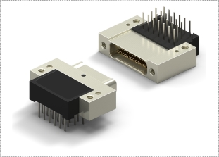
NANO PCB RIGHT ANGLE THRU-HOLE MIL-DTL-32139 CONNECTOR
PEI-Genesis carries the Ulti-Mate Nanominiature Right Angle Thru-Hole PCB Connector. Available in several layouts including two-row metal or liquid crystal polymer shells, in sizes from 9 to 65. The Ulti-Mate Nanominiature Right Angle Thru-Hole PCB Connector is built in accordance with MIL-DTL-32139.The precision formed pin and socket contacts in this PCB connector series are a single piece, crimp less contact, ready for PC board termination. Precision forming allows for the production of a rectangular integral PC tail contact, eliminating the need for crimping a solid wire, crimp resistance and soldering issues.
|
ULTIMATE NANO PCB RIGHT ANGLE THRU HOLE MATERIALS & FINISHES
Pin & Socket Contacts Pins: BeCu alloy strip per ASTM–B–194 / Sockets: BeCu per ASTM–B–194
Contact Plating Gold plate per ASTM B488, or SAE AMS 2422
Metal Shells Aluminum with electroless nickel or electrodeposited cadmium plating,Stainless Steel per ASTM A582, Titanium Alloy per MIL–T–81556, Unplated
Molded Insulators into
Metal housing or Full
plastic housing: Insulating compound per MIL–I–16923. Liquid Crystal Polymer (LCP), per MIL–M–24519 GLCP–30F, 30% Glass
Hardware Corrosion resistant steel per ASTM A 582/A582 or ASTM A 581/A581M,Passivated per SAE AMS–2700
Plating Electroless nickel or Cadmium
Note: Stainless Steel shells are available in most configurations.
ULTI-MATE NANO PCB RIGHT ANGLE THRU HOLE ELECTRICAL DATA
Contact Resistance 0.071 volt maximum drop @ 1.0 amps (.071 ohms)
Current Rating 1.0 Amp Maximum per contact
Dielectric Withstanding Voltage 250 V, RMS, 60 Hz
Insulation Resistance 5,000 Megaohms Minimum @ 100 VDC
ULTI-MATE NANO PCB RIGHT ANGLE THRU HOLE MECHANICAL
Contact Engaging and Separating Forces 5 Ounce Maximum, 0.4 Ounce Minimum
Standard Wire Sizes #30–#32 AWG
Vibration Tested in accordance with EIA–364–28, Condition IV. No Damage or resistance change greater than 10 omhs lasting longer than 10 ns
Shock Tested in accordance with EIA–364–27, Condition G. No Damage or resistence change greater than 10 ns
Durability 200 connector mating cycles tested in accordance with EIA–364–09. No Damage or resistance change greater than 10ohms lasting longer than 10ns
Salt Spray Mated connectors tested in accordance with EIA–364–26, Condition B. No exposure to base metal
Humidity Mated connectors tested in accordance with EIA–364–31, Condition B (except steps 7a and 7b). Meet DWV and IR Requirements
ULTI-MATE NANO PCB RIGHT ANGLE THRU HOLE CONTACT ARRANGEMENTS
1 row Strip 2 to 40 positions
2 row Nano D 9, 15, 21, 25, 31, 37, 51, 65
2 row Hermaphroditic 8 to 80 positions
ULTI-MATE NANO PCB RIGHT ANGLE THRU HOLE TERMINATIONS
Available Terminations Pre-wired stranded wire 30, 32 AWG
Wide choice of stranded wire types
|
|
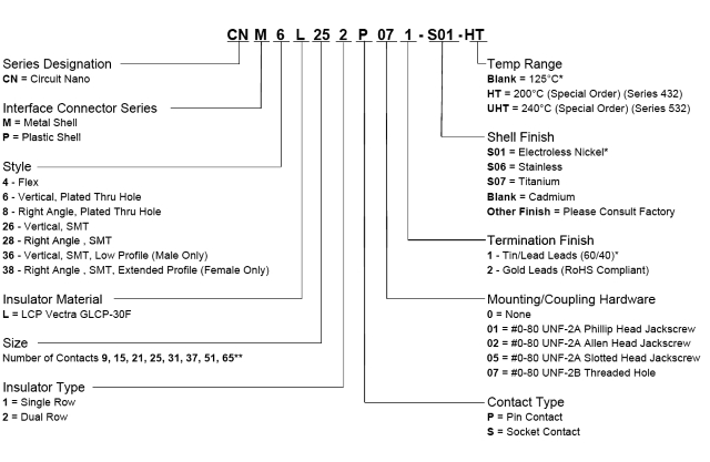
ULTI-MATE NANO PCB RIGHT ANGLE THRU HOLE CREATE PART NUMBER
|
|
ULTI-MATE NANO PCB RIGHT ANGLE THRU HOLE DIMENSIONS
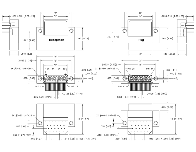
Sales Drawings
 Female Receptacle PDF
 Male Plug PDF
 Dimensions A PDF
|
|
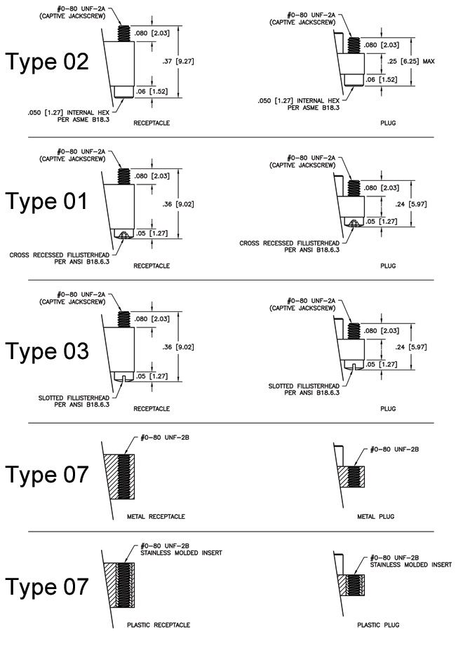
ULTI-MATE NANO PCB RIGHT ANGLE THRU HOLE HARDWARE
|


