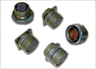
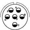
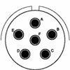
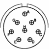
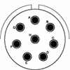
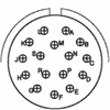
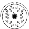
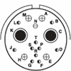
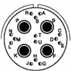
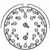
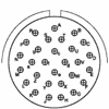
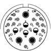
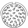
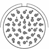
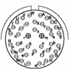
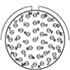
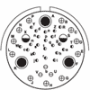
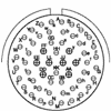
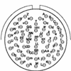
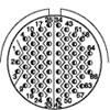
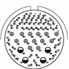
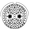
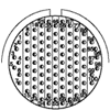
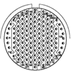
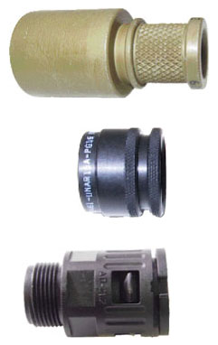
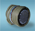
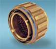
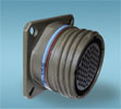
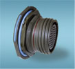
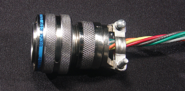
Amphenol TV-CTV Tri-Start Connectors Series III
HIGH RELIABILITY AND EMI-SHIELDING IN EXTREME ENVIRONMENTS
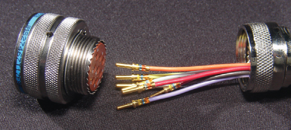
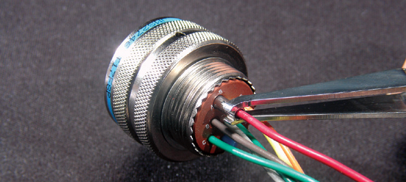
Amphenol‘s TV-CTV Tri-Start MIL-DTL-38999 Series III connectors have high-density contact arrangements in a miniature circular shell. Originally designed for the high-performance requirements of military and commercial aircraft, these circular connectors are perfect for applications requiring extremely reliable interconnections. Amphenol TV-CTV connectors are quick-mating and environmentally-sealed. See our full list of product features for Amphenol TV-CTV Tri-Start connectors in the specifications below.
These circular connectors are also available with PC Tail contacts, ideal for printed circuit board applications, either with rigid attachment or with flex print assembly. attachment- TECH
SPECS - APPLICATIONS
- CREATE PN
MILITARY - CREATE PN
COMMERCIAL - CONTACTS
& TOOLING - DIMENSIONS
- ACCESSORIES
- ASSEMBLY
|
FEATURESAMPHENOL TV-CTV FEATURES
MATERIALS & FINISHESAMPHENOL TV-CTV MATERIALS & FINISHES
Shell & Plating Aluminium Alloy Composite Stainless Steel Marine Material W - Olive drab chromate over cadmium over electroless nickel per QQ-P-416 J - Olive drab cadmium plate K - Conductive, corrosion-resistant steel passivated RB - Nickel aluminum bronze DT - DurmalonTM M - Conductive electroless S - Electrodeposited nickel W52 - Olive drab zinc cobalt F - Electroless nickel Z - Black zinc nickel (US) ZN - Black zinc nickel (EU) Contacts Copper alloy
Plating Gold-plated, 50 microinches per MIL-G-45204 type II, grade C, class I
Insulator Hard dielectric wafer which contains tines for high-reliability retention of crimp contacts
Grommet & Seals Silicone-based elastomer
Grounding Springs Beryllium copper (grounded plug only)
ELECTRICAL DATAAMPHENOL TV-CTV ELECTRICAL DATA
Contact Sizes 22D, 20, 16 and 12
Test Voltage (unmated condition) Service Rating Test Voltages N M I II Sea Level 1000 1300 1800 2300 100,000 Feet 200 200 200 200 Operating Voltage Service Rating N M I II Operating Voltage 300VAC/450VDC 400VAC/500VDC 600VAC/850VDC 900VAC/1250VDC Current Rating by Contact Size & Wire Accommodation (Test Amps) Wire Size 22D 20 16 12 10 8 28 1.5 - - - - - 26 2.0 - - - - - 24 3.0 3.0 - - - - 22 5.0 5.0 - - - - 20 - 7.5 7.5 - - - 18 - - 10.0 - - - 16 - - 13.0 - - - 14 - - - 17.0 - - 12 - - - 23.0 - - 10 (power) - - - - 33 - 8 (power) - - - - - 46 Contact Resistance of Mated Contacts End-to-End Contact Size Maximum Millivolt Drop 22D 73 20 55 16 49 12 42 10 (Power) 33 8 (Power) 26 Insulation Resistance 5,000 megohms minimum
MECHANICALAMPHENOL TV-CTV MECHANICAL
Operating Temperature W, W52, RB, J & ZN plating -65°C to 175°C (-85°F to 347°F) DT, F, M, K & S plating -65°C to 200°C (-85°F to 392°F)
Sealing Against sand, dust per MIL-STD-202 & ice resistance
Wire Sealing Range Contact Size Minimum Inches Maximum Inches Minimum MM Maximum MM 22D 0.030 0.054 0.76 1.37 20 0.040 0.083 1.02 2.11 16 0.065 0.109 1.65 2.77 12 0.097 0.142 2.46 3.61 10 0.135 0.162 3.42 4.12 10 (power) 0.135 0.162 3.42 4.12 8 (power) 0.135 0.155 3.43 3.94 8 (co-ax) 0.135 0.155 3.43 3.94 8 (twinax) 0.124 0.134 3.15 3.40 Insulation Strip Length Contact Size Strip Length 22D .125 (3.18) 20 .188 (4.77) 16 .188 (4.77) 12 .188 (4.77) 10 (Power) .335 (8.51) 8 (Power) .470 (11.94) All dimensions in inches (millimeters in parentheses) Mating Life 500/1,500 cycles minimum
Salt Spray Finish W: 500 hours per MIL-STD-1334A method 1001 condition C
Finish W52: 48-hour Finish F: 48-hour per MIL-STD-1344A method 1001 condition B Finish J & M: 1000-hour per MIL-STD-1344A method 1001 condition C Finish S & K: 500-hour per MIL-STD-1344A method 1001 condition C Finish RB: 500-hour per BS CECC 75201-002 Finish DT, DZ & ZN: 500-hour Tempature Durability Finish W: 175°C (347°F), Finish F: 200°C (392°F), mated, wired test period 1000 hours to MIL-STD-1344 Method 1005
Finish DT, M, K & S: 200°C (392°F) Finish J, RB, W52 & ZN: 175°C (347°F) Chemical Resistance Lubricating oils, hydraulic fluids, coolants, deicing fluids per MIL-STD-1344A Method 1016 condition A-1
Sine Vibration 60 grms at -55°C per MIL-DTL-38999K 4.5.22.2.1
Random Vibration 49.5 grms at ambient temperatures
Shock 300 g
EMI-Shielding Effectiveness 100 MHz to 10 GHz - minimum attenuation of 50dB
Contact Type Crimp, fibre optic, co-ax, twinax, thermocouple or printed circuit
Number of Circuits 1 to 187
Contact Insertion Rear-insertion/rear-extraction with simple plastic or high-quality metal hand tools
Contact Retention Per MIL-DTL-38999K tested to MIL-STD-1344A method 2007
Contact Size Axial Load Newtons ±10% Axial Load Pounds ±10% 22D 44 10 20 67 15 16 111 25 12 111 25 10 111 25 8 111 25 Polarization Five keyways with optional master keyway rotations (Note: insert and main keyways remain fixed)
Approvals MIL-DTL-38999
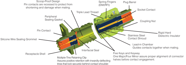
Cross-Section
EXCERPT FROM MIL-DTL-38999K
3.43.2 JAN brand. The United States Government has adopted, and is exercising legitimate control over the certification marks “JAN” and “J”, respectively, to indicate that items so marked or identified are manufactured to, and meet all the requirements of military specification. Accordingly, items acquired to, and meeting all of the criteria specified herein and in applicable specifications shall bear the certification mark “JAN” except that items too small to bear the certification mark “JAN” shall bear the letter “J”. The “JAN” or “J” shall be placed immediately before the PIN except that if such location would place a hardship on the manufacturer in connection with such marking, the “JAN” or “J” may be located on the first line above or below the PIN. Items furnished under contracts or orders which either permit or require deviation from the conditions or requirements specified herein or in applicable specifications shall not bear “JAN” or “J”. In the event an item fails to meet the requirements of this specification and the applicable specification sheets or associated detail specifications, the manufacturer shall remove the “JAN” or the “J” from the sample tested and also from all items represented by the sample. The “JAN” or “J” certification mark shall not be used on products acquired to contractor drawings or specification. The United States Government has obtained Certificate of Registration No. 504,860 for the certification mark “JAN”. Note: The “JAN” or “J” is not part of the PIN but indicates a certification. |
|
AMPHENOL TV-CTV APPLICATIONS
|
|
STEP 1: SHELLEXAMPLE
1 2 3 4 5 6 D38999/20 F A35 P N -LC SHELL STYLE FINISH LAYOUT CONTACT POLARIZATION MODIFIER STEP 1: SELECT SHELL STYLE, PLUG OR RECEPTACLE
D38999/20 D38999/24 D38999/26 STEP 2: CLASSSTEP 2: SELECT CLASS
 F = Electroless Nickel (Aluminum) K = Stainless Steel - Firewall - 45db W = Olive Drab Chromate over Cadmium (Aluminum) S = Stainless Steel/Electroless Nickel -65db J = Composite (Olive Drab Chromate over Cadmium) M = Composite (Electroless Nickel) T = Nickel -PTFE (Aluminum) Durmalon™ Contact us for details G = Space Grade Outgassed L = Corrosion-Resistant Steel/Electrodeposited Nickel Y = Hermtic Stainless Steel N = Hermetic Stainless Steel/Electrodeposited Nickel Z = Black Zinc Nickel NOTE: Part numbers will be prefixed with the United States Government Certification Marks "J" or "JAN". The Certification and Registration 504,860 for "JAN" and 1,586,261 for the "J" Certification marks. EXAMPLE: JD38999/20FA35PN STEP 3: LAYOUTSTEP 3: SELECT LAYOUT
Contacts Military D38999 Layout Service Rating Total Number 22D 20 16 12 10 8 Available in Hermetic Pin Layouts A35 M 6 6 P A98 I 3 3 P B2 I 2 2 B5 I 5 5 P B35 M 13 13 P B98 I 6 6 P B99 I 7 7 C4 I 4 4 P C8 I 8 8 P C35 M 22 22 P C98 I 10 10 P D5 II 5 5 P D15 I 15 14 1 P D18 I 18 18 P D19 I 19 19 P D35 M 37 37 P D97 I 12 8 4 P E2 M 39 38 1** E6 I 6 6 P E8 II 8 8 P E26 I 26 26 P E35 M 55 55 P E99 I 23 21 2 F11 II 11 11 P F18 M 18 14 4 F28 I 28 26 2 F32 I 32 32 P F35 M 66 66 P G11 I 11 11 G16 II 16 16 P G35 M 79 79 P G39 I 39 37 2 P G41 I 41 41 P G75 M 4 4* (See Note) H21 II 21 21 P H35 M 100 100 P H53 I 53 53 P H55 I 55 55 P J4 I 56 48 8 P J7 Twinax 99 97 2** J8 Twinax 8 8** J11 N 11 2 9 J19 I 19 19 P J20 N 30 10 13 4♦ 3** J24 I 24 12 12 P J29 I 29 29 J35 M 128 128 P J37 I 37 37 J43 I 43 23 20 J46 I 46 40 4 2* J61 I 61 61 P J90 I 46 40 4 2** P - Pin inserts only (Contact us for socket availability) Note: MS connector G75 is supplied with size 8 twinax. Propriety connector 21-75 is supplied with size 8 co-ax Coaxial type contacts are only rated for 175°C (347°F). *Co-ax **Twinax Read Less LAYOUTS BY NUMBER OF CONTACTS
Contacts 1 2 3 4
D38999 Layout - - - B2 - A98 - - C4 TV/CTV Layout 9-5Q 11-01 9-94● 11-2● 17-52Q 9-98 11-4● 11-54 13-4 # of Contacts 1-#8 1-#8** 2-#20 2-#16 2-#8** 3-#20 4-#20 4-#22D 4-#16 Service Rating M Twinax M I M I I II I Contacts 4
D38999 Layout - - - - G75 TV/CTV Layout 13-13 15-4● 17-22●Q 21-48 21-75Q # of Contacts 2-#16, 2-#12 4-#12 2-#12*, 2-#8* 4-#8*** 4-#8* or ** Service Rating I, Fiber Optic I Co-ax - M Contacts 5 6
D38999 Layout B5 D5 A35 B98 E6 - TV/CTV Layout 11-5● 15-5 9-35 11-98 17-6 6-#8** # of Contacts 5-#20 5-#16 6-#22D 6-#20 6-#12 6-#8** Service Rating I II M I I M Contacts 7 8 10
D38999 Layout B99 C8 E8 J8 C98 - TV/CTV Layout 11-99 13-8 17-8 25-8●Q 13-98 17-60Q # of Contacts 7-#20 8-#20 8-#16 8-#8** 10-#20 8-#22D, 2-#8* Service Rating I I II Twinax I I, Co-ax Contacts 11 12
D38999 Layout F11 G11 J11 D97 - TV/CTV Layout 19-11 21-11 25-11● 15-97 25-62Q # of Contacts 11-#16 11-#12 2-#20, 9-#10 2-#20, 9-#10 8-#16, 4-#8** Service Rating II I N I I Contacts 13 14 15 16
D38999 Layout B35 - D15 - D15 TV/CTV Layout 11-35 23-14● 15-15 19-31●Q 21-16 # of Contacts 13-#22D 14-#12 14-#20,1-#16 12-#22D, 1-#12, 2-#8* 16-#16 Service Rating M I I M II Contacts 17 18
D38999 Layout - - D18 F18 TV/CTV Layout 19-ADQ 19-17 15-18 19-18●Q # of Contacts 16-#20, 1#8** 10-#22D,1-#20, 4-#16, 2-#8** 18-#20 14-#22D, 4-#8** Service Rating I/Twinax M I M Contacts 19 20
D38999 Layout D19 - J19 - TV/CTV Layout 15-19● 21-79Q 25-19 17-20 # of Contacts 19-#20 17-#22D, 2-#8* 19-#12 16-#22D, 4-#12 SERVICE RATING I II I M Contacts 21 22 23 24
D38999 Layout H21 C35 E99 J24 TV/CTV Layout 23-21 13-35 17-99 25-24 # of Contacts 21-#16 22-#22D 21-#20, 2-#16 12-#16, 12-#12 Service Rating II M I I Contacts 25 26 27 28
D38999 Layout - E26 - F28 TV/CTV Layout 25-26●Q 17-26 21-29 19-28 # of Layouts 16-#20, 5-#12, 4-#8* 26-#20 19-#20, 4-#16, 4-#12 26-#20, 2-#16 Service Rating I I I I Contacts 29 30 32 37
D38999 Layout J29 J20 F32 J37 TV/CTV Layout 25-29 25-20●Q 19-32 25-37● # of Contacts 29-#16 10-#20, 13-#16, 4-#12 32-#20 37-#16 Service Rating I N I I Contacts 37 30 37
D38999 Layout D35 E2 G39 G41 - TV/CTV Layout 15-35 17-2 21-39 21-41 25-41 # of Contacts 37-#22D 38-#22D, 1-#8** 37-#20;2-#16 41-#20 22-#22D, 3-#20, 11-#16, 2-#12*, 3-#8** # of Contacts M M I I I Contacts 42 45 46
D38999 Layout - J43 J46 J90 TV/CTV Layout 25-17● 25-43● 25-46●Q 25-90 # of Contacts 36-#22D, 6-#8** 23-#20, 20-#16 40-#20, 4-#16, 2-#8* 40-#20, 4-#16, 2-#8** Service Rating M I I I Contacts 53 55
D38999 Layout H53 - E35 H55 TV/CTV Layout 23-53 23-54● 17-35 23-55● # of Contacts 53-#20 40-#22D, 9-#16, 4-#12 55-#22D 55-#20 Service Rating I M M I Contacts 56 61 66
D38999 Layout J4 J61 F35 - TV/CTV Layout 25-4 25-61 19-35 25-F4● # of Contacts 48-#20, 8-#16 61-#20 66-#22D 49-#22D, 13-#16, 4-#12 Service Rating I I M M/I Contacts 79 99 100 128
D38999 Layout G35 J7 H35 J35 TV/CTV Layout 21-35 25-7●Q 23-35 25-35 # of Contacts 79-#22D 97-#22D, 2-#8** 100-#22D 128-#22D Service Rating M Twinax M M P - Pin inserts only (Contact us for socket availability) Note: MS connector G75 is supplied with size 8 Twinax Propriety connector 21-75 is supplied with size 8 co-ax Coaxial type contacts are only rated for 175°C (347°F). * Co-ax **Twinax *** Power (EU version) available ♦ J20 is supplied with 2-#12 co-ax and 2-#12 shielded contacts Contact us for more information. Read Less STEP 4: CONTACTSTEP 4: SELECT CONTACT

P = Pin STEP 5: POLARIZATIONSTEP 5: SELECT POLARIZATION

N = Normal Standard Receptacle Plug Minor Key Location Shell Size AR & AP BR & BP CR & CP DR & DP A N A B C D E 105 102 80 35 64 91 140 132 118 140 155 131 215 248 230 205 234 197 265 320 312 275 304 240 B N 95 141 208 236 C A 113 156 182 292 D B C D E 90 53 119 51 145 156 146 141 195 220 176 184 252 255 298 242 E N 80 142 196 293 F A B C D E 135 49 66 62 79 170 169 140 145 153 200 200 200 180 197 310 244 257 280 272 G N 80 142 196 293 H A B 135 49 170 169 200 200 310 244 J C D E 66 62 79 140 145 153 200 180 197 257 280 272 STEP 6: MODIFIERSTEP 6: MODIFIER
LC = For use with standard contacts but supplied without contacts, seal plugs or tools. (P.O. must state Less Contacts.) LC is not marked on parts.
U = Universal endbell for heat shrink tube or boots. |
|
STEP 1: SHELLEXAMPLE
1 2 3 4 5 6 TVP00 RW- 9-35 P - -LC SHELL STYLE FINISH LAYOUT CONTACT POLARIZATION MODIFIER STEP 1: SELECT SHELL STYLE, PLUG OR RECEPTACLE
TVP00/TVPS00 TV01/TVS01 TV06/TVS06 TVS06RB_W88
TV09/TVS09 TVP02/TVPS02 TV07/TVS07 STEP 2: CLASSSTEP 2: SELECT CLASS
 RB = Marine Nickel Aluminum Bronze RF = Electroless Nickel (Aluminum) RK = Stainless Steel - Firewall - 45dB RW = Olive Drab Chromate over Cadmium (Aluminum) RS = Stainless Steel/Electroless Nickel - 65 dB DZ = Black Zinc Nickel (RoHS-US) DT = Durmalon (TM) (RoHS) Contact us for details Y = Hermetic Stainless Steel ZN = Black Zinc Nickel (RoHS-EU) YN = Hermetic Stainless Steel/Electroless Nickel RGF = Electroless Nickel Plated Ground Plane Aluminum, 200°C RGW = Olive Drab Cadmium Plated Ground Plane Aluminum, 175°C RQB = Same as RB, except with Quadrax Contacts RGQB = Same as RQB, Ground Plane RQF = Same as RF, except with Quadrax Contacts RGQF = Same as RGF, except with Quadrax Contacts RQK = Stainless Steel, except with Quadrax Contacts RGQK = Same as RQK, Ground Plane QDT = DurmalonTM (RoHS), except with Quadrax Contacts GQDT = Same as QDT, Ground Plane RQZ = Same as DZ, except with Quadrax Contacts RGQZ = Same as RQZ, Ground plane RQW = Same as RW, except with Quadrax Contacts RGQW = Same as RGW, except with Quadrax Contacts RX = Alternate finish, requires special variation suffix. Contact us for details # Not Firewall Capable
Please Contact Us Available with PC Pins. Contact us for details. TVPS02 - Box Mount TVS07 - Jam Nut STEP 3: LAYOUTSTEP 3: SELECT LAYOUT
Contacts Commercial TV/CTV Layout Service Rating Total Number 22D 20 16 12 10 8 Available in Hermetic Pin Layouts 9-5QG Grounded 1 1** 9-35 M 6 6 P 9-94● M 2 2 9-98 I 3 3 P 11-01 Twinax 1 1** 11-2●G I 2 2 11-4● 4 4 11-5 I 5 5 P 11-35 M 13 13 P 11-54● II 4 4 11-98 I 6 6 P 11-99 I 7 7 13-4G I 4 4 P 13-8 I 8 8 P 13-13 I,Fibre Optic 4 2 2 13-35 M 22 22 P 13-98 I 10 10 P 15-4● I 4 4 15-5G II 5 5 P 15-15 I 15 14 1 P 15-18 I 18 18 P 15-19 I 19 19 P 15-35 M 37 37 P 15-97 I 12 8 4 P 17-2● M 39 38 1** 17-6 I 6 6 P 17-8G II 8 8 P 17-20 M 20 16 4 17-22●Q Co-ax 4 2* 2* 17-26 I 26 26 P 17-35 M 55 55 P 17-52Q M 2 2** 17-60Q I/Co-ax 10 8 2* 17-99 I 23 21 2 19-ADQ I/Twinax 17 16 1** 19-11G II 11 11 P 19-17 M 17 10 1 4 2** 19-18●Q M 18 14 4** 19-28 I 28 26 2 19-31●Q M 15 12 1 2 19-32 I 32 32 P 19-35 M 66 66 P 21-11G I 11 11 21-16G II 16 16 P 21-29 I 27 19 4 4 21-35 M 79 79 P 21-39 I 39 37 2 P 21-41 I 41 41 P 21-48 4 4*** 21-75QG M 4 4* (See Note) 21-79Q II 19 17 2* 23-6QG M 6 6** 23-14● I 14 14 23-21G II 21 21 P 23-35 M 100 100 P 23-53 I 53 53 P 23-54● M 53 40 9 9 23-55● I 55 55 P 25-4 I 56 48 8 P 25-7●Q Twinax 99 97 2** 25-8●QG Twinax 8 8** 25-11● N 11 2 9 25-17● M 42 36 6** 25-19G I 19 19 P 25-20●Q N 30 10 13 4♦ 3** 25-24G I 24 12 12 P 25-26● I 25 16 4 4* 25-29G I 29 29 25-35 M 128 128 P 25-37●G I 37 37 25-41 I 41 22 3 11 2* 3** 25-43● I 43 23 20 25-46Q I 46 40 4 2* 25-61 I 61 61 P 25-62●Q I 12 8 4 25-90● I 46 60 4 2** 25-F4● M/I 66 49 13 4 ● Not tooled for 02-R Q = Available in Quadrax Layouts * Co-ax ** Twinax *** Power (EU version) available. Contact us for more information. G = Groundplane option available. 9-5 is exclusively groundplane. Note: Propriety connector 21-75 is supplied with size 8 co-ax. Coaxial type contacts are only rated for 175°C (347°F). Read Less LAYOUTS BY NUMBER OF CONTACTS
Contacts 1 2 3 4
D38999 Layout - - - B2 - A98 - - C4 TV/CTV Layout 9-5Q 11-01 9-94● 11-2● 17-52Q 9-98 11-4● 11-54 13-4 # of Contacts 1-#8 1-#8** 2-#20 2-#16 2-#8** 3-#20 4-#20 4-#22D 4-#16 Service Rating M Twinax M I M I I II I Contacts 4
D38999 Layout - - - - G75 TV/CTV Layout 13-13 15-4● 17-22●Q 21-48 21-75Q # of Contacts 2-#16, 2-#12 4-#12 2-#12*, 2-#8* 4-#8*** 4-#8* or ** Service Rating I, Fiber Optic I Co-ax - M Contacts 5 6
D38999 Layout B5 D5 A35 B98 E6 - TV/CTV Layout 11-5● 15-5 9-35 11-98 17-6 6-#8** # of Contacts 5-#20 5-#16 6-#22D 6-#20 6-#12 6-#8** Service Rating I II M I I M Contacts 7 8 10
D38999 Layout B99 C8 E8 J8 C98 - TV/CTV Layout 11-99 13-8 17-8 25-8●Q 13-98 17-60Q # of Contacts 7-#20 8-#20 8-#16 8-#8** 10-#20 8-#22D, 2-#8* Service Rating I I II Twinax I I, Co-ax Contacts 11 12
D38999 Layout F11 G11 J11 D97 - TV/CTV Layout 19-11 21-11 25-11● 15-97 25-62Q # of Contacts 11-#16 11-#12 2-#20, 9-#10 2-#20, 9-#10 8-#16, 4-#8** Service Rating II I N I I Contacts 13 14 15 16
D38999 Layout B35 - D15 - D15 TV/CTV Layout 11-35 23-14● 15-15 19-31●Q 21-16 # of Contacts 13-#22D 14-#12 14-#20,1-#16 12-#22D, 1-#12, 2-#8* 16-#16 Service Rating M I I M II Contacts 17 18
D38999 Layout - - D18 F18 TV/CTV Layout 19-ADQ 19-17 15-18 19-18●Q # of Contacts 16-#20, 1#8** 10-#22D,1-#20, 4-#16, 2-#8** 18-#20 14-#22D, 4-#8** Service Rating I/Twinax M I M Contacts 19 20
D38999 Layout D19 - J19 - TV/CTV Layout 15-19● 21-79Q 25-19 17-20 # of Contacts 19-#20 17-#22D, 2-#8* 19-#12 16-#22D, 4-#12 SERVICE RATING I II I M Contacts 21 22 23 24
D38999 Layout H21 C35 E99 J24 TV/CTV Layout 23-21 13-35 17-99 25-24 # of Contacts 21-#16 22-#22D 21-#20, 2-#16 12-#16, 12-#12 Service Rating II M I I Contacts 25 26 27 28
D38999 Layout - E26 - F28 TV/CTV Layout 25-26●Q 17-26 21-29 19-28 # of Layouts 16-#20, 5-#12, 4-#8* 26-#20 19-#20, 4-#16, 4-#12 26-#20, 2-#16 Service Rating I I I I Contacts 29 30 32 37
D38999 Layout J29 J20 F32 J37 TV/CTV Layout 25-29 25-20●Q 19-32 25-37● # of Contacts 29-#16 10-#20, 13-#16, 4-#12 32-#20 37-#16 Service Rating I N I I Contacts 37 30 37
D38999 Layout D35 E2 G39 G41 - TV/CTV Layout 15-35 17-2 21-39 21-41 25-41 # of Contacts 37-#22D 38-#22D, 1-#8** 37-#20;2-#16 41-#20 22-#22D, 3-#20, 11-#16, 2-#12*, 3-#8** # of Contacts M M I I I Contacts 42 45 46
D38999 Layout - J43 J46 J90 TV/CTV Layout 25-17● 25-43● 25-46●Q 25-90 # of Contacts 36-#22D, 6-#8** 23-#20, 20-#16 40-#20, 4-#16, 2-#8* 40-#20, 4-#16, 2-#8** Service Rating M I I I Contacts 53 55
D38999 Layout H53 - E35 H55 TV/CTV Layout 23-53 23-54● 17-35 23-55● # of Contacts 53-#20 40-#22D, 9-#16, 4-#12 55-#22D 55-#20 Service Rating I M M I Contacts 56 61 66
D38999 Layout J4 J61 F35 - TV/CTV Layout 25-4 25-61 19-35 25-F4● # of Contacts 48-#20, 8-#16 61-#20 66-#22D 49-#22D, 13-#16, 4-#12 Service Rating I I M M/I Contacts 79 99 100 128
D38999 Layout G35 J7 H35 J35 TV/CTV Layout 21-35 25-7●Q 23-35 25-35 # of Contacts 79-#22D 97-#22D, 2-#8** 100-#22D 128-#22D Service Rating M Twinax M M P - Pin inserts only (Contact us for socket availability) Note: MS connector G75 is supplied with size 8 Twinax Propriety connector 21-75 is supplied with size 8 co-ax Coaxial type contacts are only rated for 175°C (347°F). * Co-ax **Twinax *** Power (EU version) available ♦ J20 is supplied with 2-#12 co-ax and 2-#12 shielded contacts Contact us for more information. Read Less STEP 4: CONTACTSTEP 4: SELECT CONTACT

P = Pin STEP 5: POLARIZATIONSTEP 5: SELECT POLARIZATION
A = Highly-Popular Receptacle Plug Minor Key Location Shell Size AR & AP BR & BP CR & CP DR & DP 9 N A B C D E 105 102 80 35 64 91 140 132 118 140 155 131 215 248 230 205 234 197 265 320 312 275 304 240 11 N 95 141 208 236 13 A 113 156 182 292 15 B C D E 90 53 119 51 145 156 146 141 195 220 176 184 252 255 298 242 17 N 80 142 196 293 19 A B C D E 135 49 66 62 79 170 169 140 145 153 200 200 200 180 197 310 244 257 280 272 21 N 80 142 196 293 23 A B 135 49 170 169 200 200 310 244 25 C D E 66 62 79 140 145 153 200 180 197 257 280 272 STEP 6: MODIFIERSTEP 6: MODIFIER
LC = For use with standard contacts but supplied without contacts, seal plugs or tools. (P.O. must state Less Contacts.) LC is not marked on parts. W52 = Olive Drab Zinc Cobalt W88 = Heavy-Duty Plug (RB Only) |
|
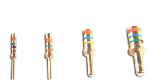
CONTACTSAMPHENOL TV-CTV CONTACTS - PINS
Color Bands Wire Range Contact Size Wire Size AWG Pin Contact 1 2 3 Wire Strip Lengths Min. Max. Wire Hole Filler Color 22D 22,24, M39029/58-360 M39029/107-620# Orange Blue Blue Red Black Black .125 (3.18) .030 (0.76) .054 (1.37) MS27488-22-2 Black 20 20,22 M39029/58-363 M39029/107-621# Orange Blue Blue Red Orange Brown .188 (4.77) .040 (1.02) .083 (2.11) MS27488-20-2 Red 16 16,18 M39029/58-364 M39029/107-622# Orange Blue Blue Red Yellow Brown .188 (4.77) .065 (1.65) .109 (2.77) MS27488-16-2 Green 12 12 & 14 M39029/58-365 M39029/107-623# Orange Blue Blue Red Green Orange .188 (4.77) .097 (2.46) .142 (3.61) MS27488-12-2 Yellow 10 10 & 12 M39029/58-528 Green Red Grey .335 (8.51) .135 (3.42) .162 (4.12) M85049/81-10 Green 8 Co-ax* M39029/ Orange Blue Violet Detailed instructions included with contacts .135 (3.42) .162 (4.12) MS27488-8-3 Red 8 Twinax** M39029/90-529 Green Red White Detailed instructions included with contacts .124 (3.15) .134 (3.40) MS27488-8-3 Red 8 Power 8 10-497448-075 - - - .470 (11.94) .135 (3.42) .162 (4.12) MS27488-8-3 Red 8 Power 10 10-497448-095 - - - .470 (11.94) .135 (3.42) .162 (4.12) MS27488-8-3 Red 8 (Power-EU) 8 900-197 - - - .393 (10.0) 0.135 (3.42) 0.162 (4.12) MS27488-8-3 Red #1500 Mating Cycle Contacts *Co-ax **Twinax call for details. For Fiber Optic Contacts, please call. AMPHENOL TV-CTV CONTACTS - SOCKETS
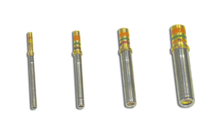
Insert head first. Trim excess Color Bands Wire Range Contact Size Wire Size AWG Socket Contact 1 2 3 Wire Strip Lengths Min. Max. Wire Hole Filler Color 22D 22,24, M39029/56-348 M39029/106-614# Orange Blue Yellow Brown Gray Yellow .125 (3.18) .030 (0.76) .054 (1.37) MS27488-22-2 Black 20 20,22 M39029/56-351 M39029/106-615# Orange Blue Green Brown Brown Green .188 (4.77) .040 (1.02) .083 (2.11) MS27488-20-2 Red 16 16,18 M39029/56-352 M39029/106-616# Orange Blue Green Brown Red Blue .188 (4.77) .065 (1.65) .109 (2.77) MS27488-16-2 Green 12 12 & 14 M39029/56-353 M39029/106-617# Orange Blue Green Brown Orange Violet .188 (4.77) .097 (2.46) .142 (3.61) MS27488-12-2 Yellow 10 10 & 12 M39029/56-527 Green Red Violet .335 (8.51) .135 (3.42) .162 (4.12) M85049/81-10 Green 8 Co-ax* M39029/59-366 Orange Blue Blue Detailed instructions included with contacts .135 (3.42) .162 (4.12) MS27488-8-3 Red 8 Twinax** M39029/91-530 Green Orange Black Detailed instructions included with contacts .124 (3.15) .134 (3.40) MS27488-8-3 Red 8 Power 8 10-497446-075 - - - .470 (11.94) .135 (3.42) .162 (4.12) MS27488-8-3 Red 8 Power 10 10-497446-095 - - - .470 (11.94) .135 (3.42) .162 (4.12) MS27488-8-3 Red 8 (Power-EU) 8 900-217 - - - .393 (10.0) 0.135 (3.42) 0.162 (4.12) MS27488-8-3 Red #1500 Mating Cycle Contacts *Co-ax **Twinax call for details. For Fiber Optic Contacts, please call. Contact Color Codes 0 Black 1 Brown 2 Red 3 Orange 4 Yellow 5 Green 6 Blue 7 Violet 8 Gray 9 White All dimensions in inches (millimeters in parentheses) CONTACT TOOLSAMPHENOL TV-CTV CONTACT TOOLS - PINS
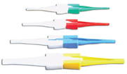
Contact Size Hand-Crimp Tool Power- Crimp Tool Turret Heads Use Locator Color Plastic Insertion/ Extraction Tool Insertion Tip Color Extraction Tip Color Metal Insertion Tool Color Band Metal Extraction Tool Color Band 22D M22520/ WA22†† M22520/ - M81969/ Green White MS27495 Black MS27495 Black White 20 M22520/ WA27F†† M22520/ Red M81969 Red Orange MS27495 Red MS27495 Red White 16 M22520/ WA27F†† M22520/ Blue M81969/ Blue White MS27495 Blue MS27495 Blue White 12 M22520/ WA27F
†† M22520/ Yellow M81969/ Yellow White DAK95 - DRK95 - - 10 TP-201423
M81969/ Gray White M81969/ Green M81969/ Green White 8 M22520/ WA22
†† M22520/2-31 (inner)
M81969/ Green - - DRK264 - - 8 M22520/ WA22
K709 (inner) M81969/ Green M81969/ Red M81969/ - - 8 - 400B-1
414DA-8N (Die) - M81969/ - Green - - DRK264 - - 8 M3SP-6 400B-1 414DA- - M81969/ - Green - - DRK264 - - 8 (Power-EU) 809-872 - 809-873 (Die Set) - M81969/14-12 - Green - - DRK264-8 - - AMPHENOL TV-CTV CONTACT TOOLS - SOCKETS
Contact Size Hand-Crimp Tool Power- Crimp Tool Turret Heads Use Locator Color Plastic Insertion/ Extraction Tool Insertion Tip Color Extraction Tip Color Metal Insertion Tool Color Band Metal Extraction Tool Color Band 22D M22520/ WA22†† M22520/ - M81969/ Green White MS27495 Black MS27495 Black White 20 M22520/ WA27F†† M22520/ Red M81969 Red Orange MS27495 Red MS27495 Red White 16 M22520/ WA27F†† M22520/ Blue M81969/ Blue White MS27495 Blue MS27495 Blue White 12 M22520/ WA27F
†† M22520/ Yellow M81969/ Yellow White DAK95 - DRK95 - - 10 TP-201423
M81969/ Gray White M81969/ Green M81969/ Green White 8 M22520/ WA22††
M22520/2-31 (inner)
M81969/ Green - - DRK264 - - 8 M22520/ WA22
K709 (inner) M81969/ Green M81969/ Red M81969/ - - 8 - 400B-1
414DA-8N (Die) - M81969/ - Green - - DRK264 - - 8 M3SP-6 400B-1 414DA- - M81969/ - Green - - DRK264 - - 8 (Power-EU) 809-872 - 809-873 (Die Set) - M81969/14-12 - Green - - DRK264-8 - - †† Contact us for more tool accessories. Contact Color Codes 0 Black 1 Brown 2 Red 3 Orange 4 Yellow 5 Green 6 Blue 7 Violet 8 Gray 9 White All dimensions in inches (millimeters in parentheses) CO-AX CONTACTSAMPHENOL TV-CTV CO-AX CONTACTS
Co-ax Pin Co-ax Socket Crimping Tools
Co-ax Contact Size Cable Type Contact Part Number Contact Part Number Crimping Tools Crimping Tools
RG-178B/U, RG-174A/U, 21-033122-564
21-033123-564
RG-174A/U, RG-180B/U,
21-033122-541
21-033123-541
M22520/5-01 w/ die set M22520/5-05 (A)or M22520/5-19 (B) or M22520/10-01 w/ die set M22520/10-07 (A) M22520/5-01 w/ die set M22520/5-05 (B) or M22520/5-41 (B) or M22520/10-01 w/ die set M22520/10-07 (B)
M22520/2-01 w/ Positioner M22520/2-10
M22520/5-01 w/ die set M22520/5-45 (A)
All dimensions in inches (millimeters in parentheses) Insertion / Extraction Tools Wire Strip Length Wire Sealing Range Co-ax Contact Size Installation Tools Installation Wire Strip Lengths Wire Sealing Range Wire Sealing Range 16 M81969/8-07 or M81969/8-08 or Contact us for details .065 (1.65) .109 (2.77) 12 M81969/8-09 or M81969/8-10 or Contact us for details .097 (2.46) .142 (3.61) 8 Hand insertion M81969/14-12 or Contact us for details .135 (3.43) .155 (3.94) All dimensions in inches (millimeters in parentheses) PCB CONTACTSAMPHENOL TV-CTV PRINTED CIRCUIT BOARD CONTACTS - PIN
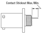
Contact Stickout Max./Min. PCB Pin Contacts Size Tail Diameter +/- .001 D38999/20 TVP00 TVP02 D38999/26 TV06 D38999/24 TV07 D38999/24 TV07 10-407552-015 22D 0.019 .335 /.280 .555 / .500 .360 / .305 .329 / .279 .286 / .236 10-407552-055 22D 0.019 .224 / .169 .444 / .389 .249 / .194 .218 / .168 .175 / .125 10-407552-085 22D 0.019 .060 / .010 .280 / .230 .085 / .035 .054 / .009 .011 / NS 10-407552-115 22D 0.019 .002 / NS .222 / NS .023 / NS NS NS 10-497640-015 20 0.019 .348 / .298 .568 / .518 .373 / .323 .342 / .297 .299 / .254 10-497640-025 20 0.019 .213 / .163 .433 / .383 .238 / .188 .207 / .162 .164 / .119 10-497640-045 20 0.019 NS NS NS NS NS 10-497596-015 20 0.025 .058 / .012 .278 / .232 .083 / .037 .052 / .011 .009 / .044 10-497596-025 20 0.025 .148 / .102 .368 / .322 .173 / .127 .142 / .101 .099 / .058 10-497596-035 20 0.025 .229 / .183 .449 / .403 .254 /.208 .223 / .182 .180 / .058 10-497596-055 20 0.025 .346 / .300 .566 / .520 .371 / .325 .340 / .299 .297 / .256 10-497695-015 16 0.040 .255 / .205 .475 / .425 .280 / .230 .249 / .204 .206 / .161 10-497630-035 16 0.062 .060 / .010 .280 / .230 .085 / .035 .054 / .009 .011 / NS 10-497630-055 16 0.062 .228 / .178 .460 / .375 .253 / .203 .244 / .177 .201 / .190 10-597502-015 12 0.081 .228 / .178 .448 / .398 .252 / .203 .222 / .177 .179 / .134 AMPHENOL TV-CTV PRINTED CIRCUIT BOARD CONTACTS - SOCKET
Contact Stickout Max./Min. PCB Pin Contacts Size Tail Diameter +/- .001 D38999/20 TVP00 TVP02 D38999/26 TV06 D38999/24 TV07 D38999/24 TV07 10-597878-011 22M 0.019 .291 / .226 .511 / .446 .316 / .251 .285 / .222 .242 / .182 10-597878-331 22M 0.019 .242 / .181 .471 / .399 .267 / .202 .258 / .180 .215 / .155 10-497623-025 22M 0.019 .868 / .803 1.088 / 1.023 .893 / .828 .862 / .802 .819 / .759 10-597878-031 22M 0.019 .348 / .283 .568 / .503 .373 / .308 .342 / .282 .299 / .239 10-597878-041 22M 0.019 .208 / .143 .428 / .363 .233 / .168 .202 / .142 .159 / .099 10-597878-071 22M 0.019 .146 / .081 .366 / .301 .171 / .106 .140 / .080 .097 / .037 10-497623-145 22M 0.019 .609 / .539 .829 / .759 .634 / .564 .603 / .538 .560 / .495 10-597878-151 22M 0.019 .423 / .358 .643 / .578 .448 / .383 .417 / .357 .374 / .314 10-497643-015 20 0.019 .348 / .294 .568 / .514 .373 / .319 .342 / .293 .299 / .250 10-497643-025 20 0.019 .213 / .159 .433 / .379 .238 / .184 .207 / .158 .164 / .115 10-497643-035 20 0.019 .555 / .501 .775 / .721 .580 / .526 .549 / .500 .506 / .457 10-497650-015 16 0.040 .255 / .205 .475 / .425 .280 / .230 .249 / .204 .206 / .161 10-597503-015 12 0.081 .184 / .130 .404 / .350 .209 / .155 .178 / .129 .135 / .086 = Standard PC tail used QUADRAX CONTACTSAMPHENOL TV-CTV QUADRAX CONTACTS
Pin Socket Contact Part Number Cable Part Number Pin Socket Inner Impedance Conductor (AWG) Electrical Protocal Draka Fileca F-4703-3, F4704-4,
Tensolite 26473/02006X-4(LD)/Gore RCN8328
Tensolite NF24Q100, NF24Q100-0,
Tensolite NF22Q100, NF22Q100-01, Thermax 956-5,
Tensolite NF26Q100, NF26Q100-01, NF26-2Q100, PIC E50426 JSFY02-1 Gore RCN8487, JSFY18 Draka Fileca F-4704-6, Gore RCN 8672 Tensolite NF24Q100-01 (same as 21-03338( )-051, uses EMI Piggyback) 21-033384-071 21-033384-091 21-033384-111 21-033384-151 21-033384-161 21-033385-071 21-033385-091 21-033385-111 21-033385-151 21-033385-161 100Ω 110Ω 110Ω 100Ω 100Ω 26 24 24 26 24
Gore RCN8513, JSF-118-3 21-033384-171 21-033385-171 100Ω 22 Tensolite NF24Q100, NF24Q100-01 for 2.5 Gbps applications 21-033384-191 21-033385-191 100Ω 24 Serial FPDP Applications USB2 (28433/02171LX-4) 21-033384-101 21-033385-101 95Ω USB2.0 Tensolite 24450/03089X-4(LD) 21-033384-211 21-033385-211 110Ω 24 IEEE 1394B Firewire JSFY02-1, JSFY18 21-033384-22 21-033385-221 110Ω 24 Contact us for details Gore RCN8487, JSFY18 21-033384-231 21-033385-231 110Ω 24 Tensolite 24450/03089X-4(LD)
PCB types and transitions are available, please contact us. AMPHENOL TV-CTV QUADRAX CONTACT TOOLS
Crimping Tools
Inner Crimp Tool Outer Crimp Tool Cable Part Number Installation Instruction Sheet Tool (setting) Positioner Tool Die Set (location) Plastic Sealing Plug Metal Sealing Plug* Metalized Piggyback Grommet Draka Fileca F-4703-3, F4704-4, Filotex ET 2PC236, FilotexET2PF870, PIC Wire E50424ABS0972, Tensolite 23450/04090X-4(LD)
Tensolite 26473/02006X-4(LD)/Gore RCN8328 (not for new designs, use 21-033450/1 series) (LD) L-2119-B M22520/ Daniels K709 M22520/5-01 M22520/ T3-4008-59P 21-033899-8Q1 21-033321-023 Tensolite NF24Q100, NF24Q100-0, 24443/9P025X-4(LD), S280W502-4, 24443/03130X-4(LD), 24443/C20714X-4(LD), 24450/0120X-4(LD), NF24-2Q100, TYCO CECRWC-18664, GORE GSC-01-81869-01, 24443/03166X-4(LD), ThermaxT956-4T200, Pic Wire E51424, Thermax MX100Q-24, NF24Q100-01-200C (Space),
Tensolite NF22Q100, NF22Q100-01, Thermax 956-5, Draka FilecaF-4704-5, GORE RCN 7688, ABS1503 KD 24
Tensolite NF26Q100, NF26Q100-01, NF26-2Q100, PIC E50426 L-2119-AB M22520/ Daniels K709 (M22520/ M22520/5-01 M22520/ T3-4008-59P 21-033899-8Q1 21-033321-023 JSFY02-1 L-2119-AD M22520/ Daniels K709 (M22520/ M22520/5-01 M22520/ T3-4008-59P 21-033899-8Q1 21-033321-023 Gore RCN8487, JSFY18 L-2119-AK M22520/ Daniels K709 (M22520/ M22520/ M22520/ T3-4008-59P 21-033899-8Q1 21-033321-023 Draka Fileca F-4704-6, L-2119-AW M22520/ Daniels K709 (M22520/ M22520/5-01 M22520/ T3-4008-59P 21-033899-8Q1 21-033321-023 Tensolite NF24Q100-01 (same as
Gore RCN8513, L-2119-BN M22520/ Daniels K709 (M22520/ M22520/5-01 M22520/ T3-4008-59P 21-033899-8Q1 21-033321-023 Tensolite NF24Q100, NF24Q100-01 for 2.5 Gbps applications L-2119-BS M22520/ Daniels K709 (M22520/ M22520/5-01 M22520/ T3-4008-59P 21-033899-8Q1 21-033321-023 USB2 (28433/02171LX-4) Contact us for details Tensolite 24450/03089X-4(LD) Contact us for details JSFY02-1, JSFY18 L-2119-CD M22520/ Daniels K709 (M22520/ M22520/5-01 M22520/ T3-4008-59P 21-033899-8Q1 21-033321-023 Gore RCN8487, JSFY18 L-2119-CR M22520/ Daniels K709 (M22520/ M22520/5-01 M22520/ T3-4008-59P 21-033899-8Q1 21-033321-023 Tensolite 24450/03089X-4(LD) Same as
*Can be used when mating with contacts on mating half. |
|
RECEPTACLESAMPHENOL TV-CTV RECEPTACLES
TVP00R/TVPS00R
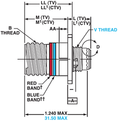
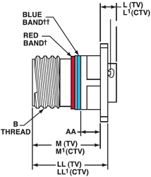
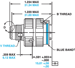
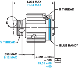
L Max. (TV) L1 Max. (CTV) Shell MS B Thread Class M +.000/ -.005 (+.000/ -.130) M1 +.000/ -.005 (+.000/ -.130) CTV Z Max. (TV) Z1 Max. (CTV) D38999 TVP02R D38999 CTVP LL +.006/ LL1 ±.005/ (±.130) CTV AA Max. Panel Thickness 9 A 0.625 .820 .773 .153 .198 .469 .205 .514 .250 .905 .908 .234 11 B 0.750 .820 .773 .153 .198 .469 .205 .514 .250 .905 .908 .234 13 C 0.875 .820 .773 .153 .198 .469 .205 .514 .250 .905 .908 .234 15 D 1.000 .820 .773 .153 .198 .469 .205 .514 .250 .905 .908 .234 17 E 1.1875 .820 .773 .153 .198 .469 .205 .514 .250 .905 .908 .234 19 F 1.250 .820 .773 .153 .198 .469 .205 .514 .250 .905 .908 .234 21 G 1.375 .790 .741 .183 .228 .500 .235 .545 .280 .905 .904 .204 23 H 1.500 .790 .741 .183 .228 .500 .235 .545 .280 .905 .904 .204 25 J 1.625 .790 .741 .183 .228 .500 .235 .545 .280 .905 .904 .204 TV01R/TVS01R Shell Size MS Shell Code B Thread Class 2A 1.0P-0.3L -TS (Plated) M +.000/ -.005 (+.000/ -.130) TV M1 +.000/ -.005 (+.000/ -.130) CTV Z MAX. (TV) Z1 MAX. (CTV) L Max. (TV) L1 Max. (CTV) LL +.006/ -.000 (± .150 -.000) TV LL1 ± .005 ±.130) CTV S ±.010 (±.250) TV S1 ±.010 (±.250) CTV GG ±.010 (±.250) TV GG1 ±.010 (±.250) CTV V Thread Metric 9 A .625 .820 (20.83) .773 (19.63) .153 (3.89) .198 (5.03) .469 (11.91) .514 (13.06) .905 (22.99) .908 (23.06) .675 (17.15) .635 (16.13) .812 (20.62) .699 (17.75) M12X1-6g 11 B .750 .820 (20.83) .773 (19.63) .153 (3.89) .198 (5.03) .469 (11.91) .514 (13.06) .905 (22.99) .908 (23.06) .800 (20.32) .765 (19.43) .905 (22.99) .875 (22.22) M15X1-6g 13 C 0.875 .820 (20.83) .773 (19.63) .153 (3.89) .198 (5.03) .469 (11.91) .514 (13.06) .905 (22.99) .908 (23.06) .925 (23.50) .885 (22.47) 1.093 (27.76) 1.007 (25.57) M18X1-6g 15 D 1.000 .820 (20.83) .773 (19.63) .153 (3.89) .198 (5.03) .469 (11.91) .514 (13.06) .905 (22.99) .908 (23.06) 1.050 (26.67) 1.100 (27.94) 1.219 (30.96) 1.140 (28.95) M22X1-6g 17 E 1.1875 .820 (20.83) .773 (19.63) .153 (3.89) .198 (5.03) .469 (11.91) .514 (13.06) .905 (22.99) .908 (23.06) 1.238 (31.45) 1.197 (30.40) 1.375 (34.93) 1.229 (31.21) M25X1-6g 19 F 1.250 .820 (20.83) .773 (19.63) .153 (3.89) .198 (5.03) .469 (11.91) .514 (13.06) .905 (22.99) .908 (23.06) 1.300 (33.02) 1.260 (32.00) 1.469 (37.31) 1.380 (35.05) M28X1-6g 21 G 1.375 .790 (20.07) .741 (18.92) .183 (4.65) .228 (5.79) .500 (12.70) .545 (13.84) .905 (35.18) .904 (22.96) 1.425 (36.20) 1.385 (35.18) 1.625 (41.28) 1.493 (37.92) M31X1-6g 23 H 1.500 .790 (20.07) .741 (18.92) .183 (4.65) .228 (5.79) .500 (12.70) .545 (13.84) .905 (35.18) .904 (22.96) 1.550 (39.37) 1.510 (38.35) 1.750 (44.45) 1.626 (41.30) M34X1-6g 25 J 1.625 .790 (20.07) .741 (18.92) .183 (4.65) .228 (5.79) .500 (12.70) .545 (13.84) .905 (35.18) .904 (22.96) 1.675 (42.55) 1.635 (41.53) 1.875 (47.63) 1.777 (45.13) M37X1-6g
T +.008/-.006 (+.200/-.130) TT +.008/-.006 (+.200/-.130)
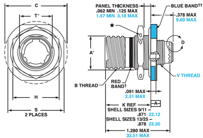
.719 (18.26) .594 (15.09) .948 (24.10) .128 (3.25) .216 (5.49) M12X1-6g .812 (20.62) .719 (18.26) 1.043 (26.50) .128 (3.25) .194 (4.93) M15X1-6g .906 (23.01) .812 (20.62) 1.137 (28.90) .128 (3.25) .194 (4.93) M18X1-6g .969 (24.61) .906 (23.01) 1.232 (31.30) .128 (3.25) .173 (4.39) M22X1-6g 1.062 (26.97) .969 (24.61) 1.323 (33.70) .128 (3.25) .194 (4.93) M25X1-6g 1.156 (29.36) 1.062 (26.97) 1.449 (36.90) .128 (3.25) .194 (4.93) M28X1-6g 1.250 (31.75) 1.156 (29.36) 1.575 (40.10) .128 (3.25) .194 (4.93) M31X1-6g 1.375 (34.92) 1.250 (31.75) 1.701 (43.30) .154 (3.91) .242 (6.15) M34X1-6g 1.500 (38.10) 1.375 (34.92) 1.823 (46.40) .154 (3.91) .242 (6.15) M37X1-6g TV07R/TVS07R Shell Size Shell Size A• +.000/ B Thread Class 2A 0.1P- 0.3L-TS (Plated) C Max. Flange Wrench D1 +.010/ D2 +.010/ H Hex +.017/ S ±.010 T• +.010/ V Thread Metric 9 A 0.669 0.6250 1.199 .700 .670 .875 1.062 .697 M12X1-6g 11 B 0.769 0.7500 1.386 .825 .770 1.000 1.250 .822 M15X1-6g 13 C 0.955 0.8750 1.511 1.010 .955 1.188 1.375 1.007 M18X1-6g 15 D 1.084 1.0000 1.636 1.135 1.085 1.312 1.500 1.134 M22X1-6g 17 E 1.208 1.1875 1.761 1.260 1.210 1.438 1.625 1.259 M25X1-6g 19 F 1.333 1.2500 1.949 1.385 1.335 1.562 1.812 1.384 M28X1-6g 21 G 1.459 1.3750 2.073 1.510 1.460 1.688 1.938 1.507 M31X1-6g 23 H 1.575 1.5000 2.199 1.635 1.585 1.812 2.062 1.634 M34X1-6g 25 J 1.709 1.6250 2.323 1.760 1.710 2.000 2.188 1.759 M37X1-6G All dimensions in inches (millimeters in parentheses) PLUGSAMPHENOL TV-CTV PLUGS
Metal Composite
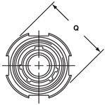
Shell Size Shell Size B Thread 0.1P-0.3L-TS-2B (Plated) Q Diameter Max. V Thread Metric 9 A 0.6250 .858 (21.80) M12X1-6g 11 B 0.7500 .984 (25.00) M15X1-6g 13 C 0.8750 1.157 (29.40) M18X1-6g 15 D 1.0000 1.280 (32.50) M22X1-6g 17 E 1.1875 1.406 (35.70) M25X1-6g 19 F 1.2500 1.516 (38.50) M28X1-6g 21 G 1.3750 1.642 (41.70) M31X1-6g 23 H 1.5000 1.768 (44.90) M34X1-6g 25 J 1.6250 1.890 (48.00) M37X1-6G All dimensions in inches (millimeters in parentheses) PANEL CUTOUTS & THICKNESSAMPHENOL TV-CTV PANEL CUTOUTS
Wall Mount Receptacle Jam Nut Receptacle
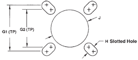
D38999/24 & D38999 TV/CTV G1 G2 H Diameter +.005 (+.130) -.000 (.000) Front Mount Back Mount A +.010 (+.025) -.000 (.000) B +.000 (000) -.010 (-.025) A 9 .719 (18.26) .59 (15.09) .130 (3.25) .516 (13.11) .656 (16.66) .693 (17.60) .657 (16.70) B 11 .81 (20.62) .71 (18.26) .130 (3.25) .625 (15.88) .796 (20.22) .825 (20.96) .770 (19.59) C 13 .91 (23.01) .81 (20.62) .130 (3.25) .750 (19.05) .922 (23.42) 1.010 (25.65) .955 (24.26) D 15 .97 (24.61) .90 (23.01) .130 (3.25) .906 (23.01) 1.047 (26.59) 1.135 (28.83) 1.085 (27.56) E 17 1.06 (26.97) .96 (24.61) .130 (3.25) 1.016 (25.81) 1.219 (30.96) 1.260 (32.01) 1.210 (30.73) F 19 1.16 (29.36) 1.06 (26.97) .130 (3.25) 1.141 (28.98) 1.297 (32.94) 1.385 (35.18) 1.335 (33.91) G 21 1.25 (31.75) 1.15 (29.36) .130 (3.25) 1.266 (32.16) 1.422 (36.12) 1.510 (38.35) 1.460 (37.08) H 23 1.38 (34.93) 1.25 (31.75) .155 (3.94) 1.375 (34.93) 1.547 (39.29) 1.635 (41.53) 1.585 (40.29) J 25 1.50 (38.10) 1.37 (34.93) .155 (3.94) 1.484 (37.69) 1.672 (42.47) 1.760 (44.70) 1.710 (43.43) AMPHENOL TV-CTV PANEL THICKNESS
Wall Mount Receptacle Jam Nut Receptacle All dimensions in inches (millimeters in parentheses) |
|
TOOLING ACCESSORIESAMPHENOL TV-CTV CONNECTOR TOOLS
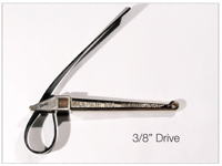
TG70 Strap Wrench
TG69P Non-Marring Adjustable Endbell Pliers for Field Service 600 Series Production System The 600 series is a complete system for the proper assembly and torquing of connector endbells. The system includes a bench-mounted or hand-held torque wrench, plug and receptacle holders, and a range of endbell tightening tools. When used together, these tools provide the user with consistent endbell installations. Each item is shipped with detailed assembly instructions.
Plug and Receptacle Holders
Pins with Alternate Keying Sockets with Alternate Keying PA = E SA = F PB = R SB = T PC = W SC = X PD = Y SD = Z AMPHENOL TV-CTV MIL-DTL-38999 Series III for TV-CTV Shell Size Receptacles Plugs A 9 600H005-9R# 600H005-9P# B 11 600H005-11R# 600H005-11P# C 13 600H005-13R# 600H005-13P# D 15 600H005-15R# 600H005-15P# E 17 600H005-17R# 600H005-17P# F 19 600H005-19R# 600H005-19P# G 21 600H005-21R# 600H005-21Pv H 23 600H005-23R# 600H005-23P# J 25 600H005-25R# 600H005-25P# # Add polarizations: N, A, B, C, D, E ACCESSORIESAMPHENOL TV-CTV DUMMY RECEPTACLES, DUST CAPS & PLUG CAPS
Receptacle Dust Caps D38999 TV/CTV Dummy Receptacles For Flanged For Jam Nut Plug Cap A 9 D38999/22A** D38999/33**9R D38999/33**9N D38999/32**9## B 11 D38999/22B** D38999/33**11R D38999/33**11N D38999/32**11## C 13 D38999/22C** D38999/33**13R D38999/33**13N D38999/32**13## D 15 D38999/22D** D38999/33**15R D38999/33**15N D38999/32**15## E 17 D38999/22E** D38999/33**17R D38999/33**17N D38999/32**17## F 10 D38999/22F** D38999/33**19R D38999/33**19N D38999/32**19## G 21 D38999/22G** D38999/33**21R D38999/33**21N D38999/32**21## H 23 D38999/22H** D38999/33**23R D38999/33**23N D38999/32**23## J 25 D38999/22J** D38999/33**25R D38999/33**25N D38999/32**25## Olive drab chromate over cadmium over nickel (500-hour salt spray) Finish 10-No Suffix Olive Drab, Cadmium, -XX9 Electroless Nickel -XXG † Select code for plating AMPHENOL TV-CTV CABLE CLAMPS
D38999 TV/CTV Low-Cost Self-Locking Low-Cost Self-Locking Cable Range Cable Range A 9 M85049/38-9** M85049/38S9** M85049/39-9** M85049/39S9** .098 (2.49) .234 (5.94) B 11 M85049/38-11** M85049/38S11** M85049/39-11** M85049/39S11** .153 (3.89) .234 (5.94) C 13 M85049/38-13** M85049/38S13** M85049/39-13** M85049/39S13** .190 (4.83) .328 (8.33) D 15 M85049/38-15** M85049/38S15** M85049/39-15** M85049/39S15** .260 (6.60) .457 (11.61) E 17 M85049/38-17** M85049/38S17** M85049/39-17** M85049/39S17** .283 (7.19) .614 (15.60) F 19 M85049/38-19** M85049/38S19** M85049/39-19** M85049/39S19** .325 (8.25) .634 (16.10) G 21 M85049/38-21** M85049/38S21** M85049/39-21** M85049/39S21** .343 (8.71) .698 (17.73) H 23 M85049/38-23** M85049/38S23** M85049/39-23** M85049/39S23** .381 (9.68) .823 (20.90) J 25 M85049/38-25** M85049/38S25** M85049/39-25** M85049/39S25** .418 (10.62) .853 (21.67) ** Plating Material W = Olive drab chromate over cadmium over nickel (1000-hour salt spray) N = Electroless nickel (Fluid-resistant) A = Black anodize S = Stainless steel All dimensions in inches (millimeters in parentheses) AMPHENOL TV-CTV STANDARD MIL-SPEC ACCESSORIES
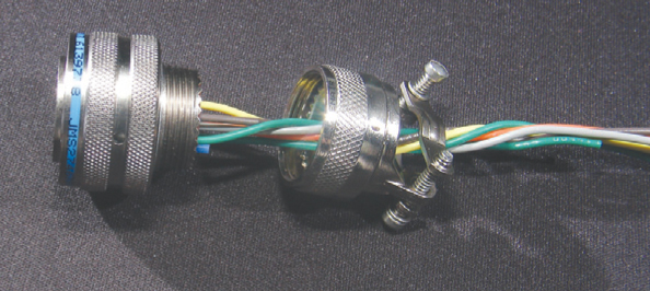
Sealed EMI/RFI Orientation Endbell Type Description M85049/69 Y N S Heat Shrink Boot Adapters Designed for use with straight or right angle shrink boots. A knurled rear section with a boot groove provides excellent surface for the boot to grab the metal endbell. Available with lock wire and drain holes. See Heat Shrink Boots. M85049/21 N N S Shield Termination Back Shell Non-environmental designed for use with jacketed cable. Allow extra space to break out the wires and still provide stain relief clamping to the outside of the cable jacket. M85049/18 Y Y S Extender Back Shell This EMI/RFI-shielding, environmentally-sealed endbell features a standard-style cable clamp with gland seal at the end of an extender-style backshell. M85049/19 N Y S Extender Back Shell This EMI/RFI-shielding, non-environmentally-sealed endbell features a standard-style cable clamp. Banding Y Y
Banding Adapter Banding adapters utilize a band of metal that fastens and grounds cable shields to the outside of endbells. This method of terminating shields has advantages in that they typically use tools to tighten and trim the bands. These tools make the termination tight, repeatable, reworkable (if you make a mistake, just cut the band off and start again) and facilitates service. Banding adapters help lower the total applied cost by having simpler designs that have fewer parts with uncomplicated assembly procedures. M85049/14S N N S E-Nut Wire seal compression nut AMPHENOL TV-CTV LOW-COST UNIVERSAL ENDBELLS
CA = Flexible Conduit Adapter 
Q = Quick Thread Converter For use with Standard Accessoried Thread MS3057 
(Use when needed) |
|
WIRE STRIPPINGAMPHENOL TV-CTV WIRE STRIPPING
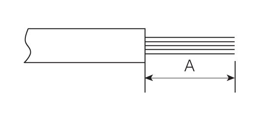
WIRE SIZE A 22, 22M, 22D .125 (3.18) 20 .188 (4.77) 16 .188 (4.77) 12 .188 (4.77) 10 .355 (8.51) 8 (power) .470 (11.99) All dimensions in inches (millimeters in parentheses) CONTACT CRIMPINGAMPHENOL TV-CTV CONTACT CRIMPING
Correct
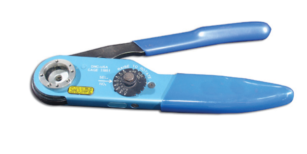
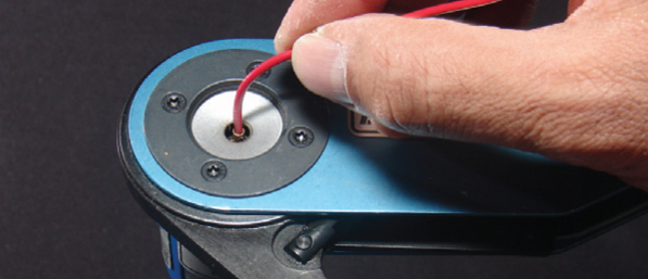
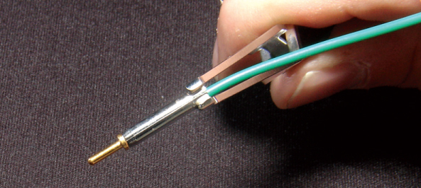
STEP 1: Insert wire into rear of contact. Wire insulation must press against rear of contact. Wire must be visible through inspection hole. STEP 2: M22520 series crimp tool and locator is recommended. See Contact and Tool Table for choice of turret head and selection setting according to contact size, part number and wire gauge size. STEP 3: Insert contact and wire into tool jaws. To crimp, squeeze handles together fully until ratchet releases and allows handles to expand; otherwise, contact cannot be extracted from tool jaws. Maintain slight insertion pressure on wire while crimping contact to wire. CONTACT INSERTIONAMPHENOL TV-CTV CONTACT INSERTION
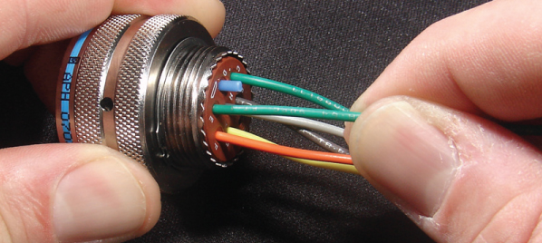
STEP 1: Remove hardware from plug or receptacle and slip over wire bundle in proper order for reassembly. STEP 2: Using proper plastic or metal insertion tool for corresponding contact, position wire in tip of the tool so that the tool tip presses against the contact shoulder. STEP 3: Press tool against contact shoulder and, with firm and even pressure, insert wired contact and tool tip into center contact cavity.
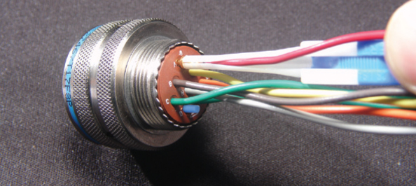
STEP 4: When contact bottoms, a slight “click” can be heard as tines of metal retaining clip snap into place behind contact shoulder. STEP 5: Remove tool and pull back lightly on wire to make sure contact is properly seated. Repeat operation with remainder of contacts to be inserted, beginning with the center cavity and working outward in alternating rows. STEP 6: After all contacts are inserted, fill any empty cavities with wire sealing plugs. Reassemble plug or receptacle hardware. CONTACT EXTRACTIONAMPHENOL TV-CTV CONTACT EXTRACTION
STEP 1: Remove hardware from plug or receptacle and slide hardware back along wire bundle. STEP 2: Using plastic or metal extraction tool with proper color code corresponding to contact size, place wire in tool. STEP 3: Insert tool into contact cavity until tool tip bottoms against the contact shoulder, expanding clip retaining tines.
STEP 4: Hold wire firmly in tool and extract wired contact and tool. Repeat operation for all contacts to be extracted. STEP 5: Fill any empty cavities with wire sealing plugs. Reassemble plug or receptacle hardware. Note: LJT series shown. |
Philadelphia
19116
Click here for the contact information of the branch nearest you.


