ITT Cannon MDM Series | MIL-DTL-83513 Micro-D Connectors
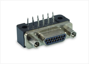
HIGHLY-RELIABLE MINIATURE D-SUB MIL-DTL-83513 PIN CONNECTOR
ITT Cannon's MDM series Micro-D connectors are compact, high-density solutions ideal for applications where standard D-Sub connectors are too large or heavy. These connectors feature a robust yet lightweight aluminum shell and a highly reliable twist pin contact system with Pos-A-Line alignment. Perfect for medical equipment, instrumentation, and satellite systems, these connectors ensure exceptional performance and reliability. Part numbers commence with M83513, while ITT Cannon part numbers start with MDM. For comprehensive details on the ITT Cannon MDM series, please refer to the product specifications below.
|
FEATURESITT CANNON MDM SERIES FEATURES
MATERIALS & FINISHESITT CANNON MDM SERIES MATERIALS & FINISHES
Shell Aluminum alloy per QQ-A-200/8 (6061-T6)
Plating Yellow chromate over cadmium per QQ-P-416, Type II, Class 3 over electroless nickel underplate or for Zero cadmium and space applications, electroless nickel per MIL-C-26074, Class 3 of 4, Grade B
Contacts Pins - outer strands BeCu alloy per QQ-C-530
Inner strands - copper alloy per QQ-W-343, Type S Sleeve - copper alloy per ASTM B75 Sockets - copper alloy per ASTM B140 Plating Minimum 50 microinches gold per MIL-G-45204, Type II, Grade C, Class 1, over copper flash
Insulator Liquid Crystal Polymer (LCP) A130 or C130 color black per MIL-M-24519, Type GLCP-30
Epoxy Wire Seal Pre-wired harnesses - Hysol EE4215/HD3561 (black)
Printed circuit - Hysol MG8F-0134 (black) Wire 25 AWG Solid copper per QQ-W-343, Type S, Plated Tin 100 microinches or gold 10 microinches MDM - 26 AWG Teflon wire 7/34 per MIL-W-16878/4, Type E Yellow or Color Coded per MIL-STD-681 System 1 M83513 - 26 AWG Teflon wire 19/38 per MIL-W-22759 White or Color Coded per MIL-STD-681 System 1 except wire number equals contact cavity number minus 1, and 10 colors repeating
ELECTRICAL DATAITT CANNON MDM SERIES ELECTRICAL DATA
Test Voltage 600 Vac at sea level
150 Vac at 70,000 feet (23410 meters) Current Rating 3 Amps
Contact Resistance 8 milliohms maximum at 3 amps
10 milliohms maximum at 1 milliamps: MIL-STD-202 Method 307 Insulation Resistance 5000 megohms minimum at 500 Vdc
1000 megohms minimum after condition; MIL-STD-1344 Method 1002 Magnetic Permeability 2.0μ (connectors less hardware)
Thermal Vacuum Outgassing per NASA SP-R-0022 (space class only)
Printed circuit - Hysol MG8F-0134 (black) Total Mass Loss 1.0 percent maximum
Volatile Condensable Material (VCM) 0.1 percent maximum MECHANICALITT CANNON MDM SERIES MECHANICAL
Operating Temperature -55°C to +125°C (-67°F to +257°F)
Sealing Humidity
Mating Life 500 cycles minimum
Salt Spray 48 hours MIL-STD-1344 Method 1001 Condition B
Chemical Resistance Cleaning solvents: Perchloroethylene US practical grade, 2 hours Lubricating oil aircraft turbine engine, synthetic base 20 hours Coolant (coolanol 25 or equivalent) 1 hour +/- 1 minute
Vibration 20g’s MIL-STD-1344 Method 2005 Condition IV
Shock 50g’s MIL-STD-1344 Method 2004 Condition C
Contact Type Pre-wired, solder, printed circuit board (gold-plated)
Number of Circuits 9 to 100
Contact Retention 5 pounds minimum
Polarization D-shaped shells
|
|
ITT CANNON MDM SERIES APPLICATIONS
|
|
STEP 1: MATERIALITT CANNON MDM SERIES PART NUMBER EXAMPLE
1 2 3 4 5 6 MDM -15 P S -A174 SHELL STYLE LAYOUT CONTACT TERMINATIONS HARDWARE MOD CODE STEP 1: CHOOSE INSERT MATERIAL TYPE
*Note: Previous Material was Diallyl Phthalate or Polyester STEP 4: TERMINATIONSTEP 4: CHOOSE TERMINATION 
BS = Straight Printed BR = Right Angle S = Solder Cup 26
CBR = Narrow Profile Wire Terminations** Code Length Inches (mm) L61 .125 (3.18) L56 .150 (3.81) L57 .190 (4.83) L39 .250 (6.35) L58 .375 (9.52) L1 .500 (12.70) L14 .750 (19.05) L2 1.000 (25.40) L7 1.500 (38.11) L6 2.000 (50.80) L16 2.500 (63.50) L10 3.000 (76.20) 16878/4 Standard Wire Terminations** Yellow Color Coded Length Inches (mm) H020 H027 3 (76.2) H019 H016 6 (152.4) H026 H034 8 (203.2) H029 H025 10 (254.0) H028 H002 12 (304.8) H001 H003 18 (457.2) H038 H023 20 (508.0) H009 H004 24 (609.6) H010 H005 30 (762.0) H011 H006 36 (914.4) H013 H048 48 (1219.2) H017 H046 72 (1828.8) H042 H041 120 (3048.0) * Note Previous Material was Diallyl Phthalate or Polyester ** For wire lengths and types other than listed, please contact us. Dimensions are shown in inches (millimeters in parentheses) STEP 5: HARDWARESTEP 5: CHOOSE HARDWARE
T = Threaded; A = Large Through Hole; B = Standard Through Hole; B1 = Through Hole for size 100;
F = Float Mount
P = Jackpost
K = Jackscrew
L = Low Profile Jackscrew M = Click here for more information STEP 6: MOD CODESTEP 6: CHOOSE MOD CODE
A174 = Electroless nickel (RoHS) A141 = Irridate / alodine F222 = Special high-temperature version A172 = Gold over nickel A30 = Black anodized HOW TO ORDER M83513 PART NUMBERSITT CANNON MDM SERIES HOW TO SELECT CONNECTOR PART #
EXAMPLE: M83513/ 25-AO1 * † Same Number Leads: Example C = Cadmium N = No Jackpost ITT CANNON MDM SERIES PLUGS
 Example: M83513/01-
Pre-Wired Leads White Color Coded White Color Coded # of Circuits 18" 36" 72" 18" 36" 72" 18" 36" 72" 18" 36" 72" 9 03-A01* 03-A02* 03-A13* 03-A03* 03-A04* 03-A14* 03-A09N 03-A10N 03-A15N 03-A11N 03-A12N 03-A16N 15 03-B01* 03-B02* 03-B13* 03-B03* 03-B04* 03-B14* 03-B09N 03-B10N 03-B15N 03-B11N 03-B12N 03-B16N 21 03-C01* 03-C02* 03-C13* 03-C03* 03-C04* 03-C14* 03-C09N 03-C10N 03-C15N 03-C11N 03-C12N 03-C16N 25 03-D01* 03-D02* 03-D13* 03-D03* 03-D04* 03-D14* 03-D09N 03-D10N 03-D15N 03-D11N 03-D12N 03-D16N 31 03-E01* 03-E02* 03-E13* 03-E03* 03-E04* 03-E14* 03-E09N 03-E10N 03-E15N 03-E11N 03-E12N 03-E16N 37 03-F01* 03-F02* 03-F13* 03-F03* 03-F04* 03-F14* 03-F09N 03-F10N 03-F15N 03-F11N 03-F12N 03-F16N 51 03-G01* 03-G02* 03-G13* 03-G03* 03-G04* 03-G14* 03-G09N 03-G10N 03-G15N 03-G11N 03-G12N 03-G16N 100 03-H01* 03-H02* 03-H13* 03-H03* 03-H04* 03-H14* 03-H09N 03-H10N 03-H15N 03-H11N 03-H12N 03-H16N Bold part numbers are in stock; choose for fast delivery. ITT CANNON MDM SERIES RECEPTACLES

Example: M83513/02-
Pre-Wired Leads White Color Coded White Color Coded # of Circuits 18" 36" 72" 18" 36" 72" 18" 36" 72" 18" 36" 72" 9 04-A01* 04-A02* 04-A13* 04-A03* 04-A04* 04-A14* 04-A09N 04-A10N 04-A15N 04-A11N 04-A12N 04-A16N 15 04-B01* 04-B02* 04-B13* 04-B03* 04-B04* 04-B14* 04-B09N 04-B10N 04-B15N 04-B11N 04-B12N 04-B16N 21 04-C01* 04-C02* 04-C13* 04-C03* 04-C04* 04-C14* 04-C09N 04-C10N 04-C15N 04-C11N 04-C12N 04-C16N 25 04-D01* 04-D02* 04-D13* 04-D03* 04-D04* 04-D14* 04-D09N 04-D10N 04-D15N 04-D11N 04-D12N 04-D16N 31 04-E01* 04-E02* 04-E13* 04-E03* 04-E04* 04-E14* 04-E09N 04-E10N 04-E15N 04-E11N 04-E12N 04-E16N 37 04-F01* 04-F02* 04-F13* 04-F03* 04-F04* 04-F14* 04-F09N 04-F10N 04-F15N 04-F11N 04-F12N 04-F16N 51 04-G01* 04-G02* 04-G13* 04-G03* 04-G04* 04-G14* 04-G09N 04-G10N 04-G15N 04-G11N 04-G12N 04-G16N 100 04-H01* 04-H02* 04-H13* 04-H03* 04-H04* 04-H14* 04-H09N 04-H10N 04-H15N 04-H11N 04-H12N 04-H16N Bold part numbers are in stock; choose for fast delivery. Read Less ITT CANNON MDM SERIES HOW TO SELECT HARDWARE PART #
EXAMPLE: M83513/05- 05 Low Profile Slotted M83513/05- Slotted Jackscrew Allen Head Jackscrew Connector Size Low Profile High Profile Low Profile High Profile Jackpost 9 - 51 05 06 02 03 07 100 15 16 12 13 17 ITT CANNON MDM SERIES PLUGS Example: M83513/01-
Pre-wired Leads 25 AWG Solid 1/2" Uninsulated" Pre-wired Leads 25 AWG Solid 1" Uninsulated"
Right Angle Printed Circuit Tails Condensed Footprint Length in inches Right Angle Printed Circuit Tails Wide Footprint Length in inches # of Circuits Tinned Leads Gold Leads Tinned Leads Gold Leads Solder 0.109 0.140 0.172 0.109 0.140 0.172 0.109 0.140 0.172 9 03A07* 03A05* 03A08* 03A06* 01A* 22A01*† 22A02*† 22A03*† 10A01*† 10A02*† 10A03*† 16A01*† 16A02*† 16A03*† 15 03B07* 03B05* 03B08* 03B06* 01B* 22B01*† 22B02*† 22B03*† 10B01*† 10B02*† 10B03*† 16B01*† 16B02*† 16B03*† 21 03C07* 03C05* 03C08* 03C06* 01C* 22C01*† 22C02*† 22C03*† 10C01*† 10C02*† 10C03*† 16C01*† 16C02*† 16C03*† 25 03D07* 03D05* 03D08* 03D06* 01D* 22D01*† 22D02*† 22D03*† 10D01*† 10D02*† 10D03*† 16D01*† 16D02*† 16D03*† 31 03E07* 03E05* 03E08* 03E06* 01E* 22E01*† 22E02*† 22E03*† 10E01*† 10E02*† 10E03*† 16E01*† 16E02*† 16E03*† 37 03F07* 03F05* 03F08* 03F06* 01F* 22F01*† 22F02*† 22F03*† 10F01*† 10F02*† 10F03*† 16F01*† 16F02*† 16F03*† 51 03G07* 03G05* 03G08* 03G06* 01G* 22G01*† 22G02*† 22G03*† 10G01*† 10G02*† 10G03*† 16G01*† 16G02*† 16G03*† 100 03H07* 03H05* 03H08* 03H06* 01H* 22H01*† 22H02*† 22H03*† 10H01*† 10H02*† 10H03*† 16H01*† 16H02*† 16H03*† ITT CANNON MDM SERIES RECEPTACLES
Example: M83513/02-
Pre-wired Leads 25 AWG Solid 1/2" Uninsulated" Pre-wired Leads 25 AWG Solid 1" Uninsulated"
Right Angle Printed Circuit Tails Condensed Footprint Length in inches Right Angle Printed Circuit Tails Wide Footprint Length in inches # of Circuits Tinned Leads Gold Leads Tinned Leads Gold Leads Solder 0.109 0.140 0.172 0.109 0.140 0.172 0.109 0.140 0.172 9 04A07* 04A05* 04A08* 04A06* 02A* 25A01*† 25A02*† 25A03*† 13A01*† 13A02*† 13A03*† 19A01*† 19A02*† 19A03*† 15 04B07* 04B05* 04B08* 04B06* 02A* 25B01*† 25B02*† 25B03*† 13B01*† 13B02*† 13B03*† 19B01*† 19B02*† 19B03*† 21 04C07* 04C05* 04C08* 04C06* 02C* 25C01*† 25C02*† 25C03*† 13C01*† 13C02*† 13C03*† 19C01*† 19C02*† 19C03*† 25 04D07* 04D05* 04D08* 04D06* 02D* 25D01*† 25D02*† 25D03*† 13D01*† 13D02*† 13D03*† 19D01*† 19D02*† 19D03*† 31 04E07* 04E05* 04E08* 04E06* 02E* 25E01*† 25E02*† 25E03*† 13E01*† 13E02*† 13E03*† 19E01*† 19E02*† 19E03*† 37 04F07* 04F05* 04F08* 04F06* 02F* 25F01*† 25F02*† 25F03*† 13F01*† 13F02*† 13F03*† 19F01*† 19F02*† 19F03*† 51 04G07* 04G05* 04G08* 04G06* 02G* 25G01*† 25G02*† 25G03*† 13G01*† 13G02*† 13G03*† 19G01*† 19G02*† 19G03*† 100 04H07* 04H05* 04H08* 04H06* 02H* 25H01*† 25H02*† 25H03*† 13H01*† 13H02*† 13H03*† 19H01*† 19H02*† 19H03*† *C = Cadmium N = Electroless Nickel †N = No Jackpost Insertion P = Jackpost Insertion Read Less Dimensions are shown in inches (millimeters in parentheses) |
|
PLUGSITT CANNON MDM SERIES PLUG DIMENSIONS (CONFORMS TO MIL-DTL-83513)
Part Number by A Max. B Max. C Max. D Max. E Max. F G Max. Average Weights** oz. (gm.) +/-5% MDM-9P* .785 (19.94) .334 (8.48) .400 (10.16) .270 (6.86) .308 (7.82) .565 (14.35) .185 (4.70) .063 (1.79) MDM-15P* .935 (23.75) .484 (12.29) .550 (13.97) .270 (6.86) .308 (7.82) .715 (18.16) .185 (4.70) .084 (2.39) MDM-21P* 1.085 (27.56) .634 (16.10) .700 (17.78) .270 (6.86) .308 (7.82) .865 (21.97) .185 (4.70) .105 (2.99) MDM-25P* 1.185 (30.10) .734 (18.64) .800 (20.32) .270 (6.86) .308 (7.82) .965 (24.51) .185 (4.70) .119 (3.39) MDM-31P* 1.335 (33.91) .884 (22.45) .950 (24.13) .270 (6.86) .308 (7.82) 1.115 (28.32) .185 (4.70) .140 (3.99) MDM-37P* 1.485 (37.72) 1.034 (26.26) 1.100 (27.94) .270 (6.86) .308 (7.82) 1.265 (32.13) .185 (4.70) .161 (4.59) MDM-51P* 1.435 (36.45) .984 (24.99) 1.050 (26.67) .310 (7.87) .351 (8.92) 1.215 (30.86) .228 (5.79) .193 (5.50) MDM-100P* 2.170 (55.12) 1.384 (35.15) 1.442 (36.63) .360 (9.14) .394 (10.01) 1.800 (45.72) .271 (6.88) .500 (14.3) ITT CANNON MDM SERIES PANEL MOUNTING DIMENSIONS (SIZES 9-100)
All dimensions are shown in inches (millimeters in parentheses) RECEPTACLESITT CANNON MDM SERIES RECEPTACLE STYLES
ITT CANNON MDM SERIES RECEPTACLE (MDM-100 ONLY)
Part Number by A Max. B Max. C Max. D Max. E Max. F G Max. Average Weights** oz. (gm.) +/-5% MDM-9S* .785 (19.94) .402 (10.21) .400 (10.16) .270 (6.86) .308 (7.82) .565 (14.35) .253 (6.43) .063 (1.79) MDM-15S* .935 (23.75) .552 (13.97) .550 (13.97) .270 (6.86) .308 (7.82) .715 (18.16) .253 (6.43) .083 (2.37) MDM-21S* 1.085 (27.56) .702 (17.83) .700 (17.78) .270 (6.86) .308 (7.82) .865 (21.97) .253 (6.43) .104 (2.97) MDM-25S* 1.185 (30.10) .802 (20.37) .800 (20.32) .270 (6.86) .308 (7.82) .965 (24.51) .253 (6.43) .118 (3.36) MDM-31S* 1.335 (33.91) .952 (24.18) .950 (24.13) .270 (6.86) .308 (7.82) 1.115 (28.32) .253 (6.43) .139 (3.96) MDM-37S* 1.485 (37.72) 1.102 (27.99) 1.100 (27.94) .270 (6.86) .308 (7.82) 1.265 (32.13) .253 (6.43) .160 (4.56) MDM-51S* 1.435 (36.45) 1.052 (26.72) 1.050 (26.67) .310 (7.87) .351 (8.92) 1.215 (30.86) .296 (7.52) .188 (5.35) MDM-100S* 2.170 (55.12) 1.508 (38.10) 1.442 (36.63) .360 (9.14) .394 (10.01) 1.800 (45.72) .394 (10.01) 1.040 (29.5) * Add lead type and length; see Create Part Number ** Weight given is 1/2", uninsulated, solid, #25 AWG gold plated copper pigtails All dimensions are shown in inches (millimeters in parentheses) ITT CANNON MDM SERIES PANEL MOUNTING DIMENSIONS (SIZES 9-100)
BS SERIESITT CANNON MDM SERIES BS (BOARD STRAIGHT) SERIES
NOTE: Standard lead termination is #24 AWG, solid copper, solder or tin dipped. Part # by Shell Size A Max. B ± .007 (.018) C ± .005 (.013) D Max. E Max. F ± .005 (0.13) G Max. H Max. J Max. K Max. MDM-9PBS* 1.390 (35.31) 1.150 (29.21) .565 (14.35) .785 (19.94) .334 (8.48) .185 (4.70) .308 (7.82) .165 (4.19) .355 (9.02) .555 (14.10) MDM-9SBS* 1.390 (35.31) 1.150 (29.21) .565 (14.35) .785 (19.94) .402 (10.21) .253 (6.43) .308 (7.82) .165 (4.19) .355 (9.02) .555 (14.10) MDM-15PBS* 1.390 (35.31) 1.150 (29.21) .715 (18.16) .935 (23.75) .484 (12.29) .185 (4.70) .308 (7.82) .165 (4.19) .355 (9.02) .555 (14.10) MDM-15SBS* 1.390 (35.31) 1.150 (29.21) .715 (18.16) .935 (23.75) .552 (13.97) .253 (6.43) .308 (7.82) .165 (4.19) .355 (9.02) .555 (14.10) MDM-21PBS* 1.690 (43.93) 1.450 (36.83) .865 (21.97) 1.085 (27.56) .634 (16.10) .185 (4.70) .308 (7.82) .165 (4.19) .355 (9.02) .555 (14.10) MDM-21SBS* 1.690 (43.93) 1.450 (36.83) .865 (21.97) 1.085 (27.56) .702 (17.83) .253 (6.43) .308 (7.82) .165 (4.19) .355 (9.02) .555 (14.10) MDM-25PBS* 1.740 (44.20) 1.500 (38.10) .965 (24.51) 1.185 (30.10) .734 (18.64) .185 (4.70) .308 (7.82) .165 (4.19) .355 (9.02) .555 (14.10) MDM-25SBS* 1.740 (44.20) 1.500 (38.10) .964 (24.51) 1.185 (30.10) .802 (20.37) .253 (6.43) .308 (7.82) .165 (4.19) .355 (9.02) .555 (14.10) MDM-31PBS* 2.040 (51.82) 1.800 (45.72) 1.115 (28.32) 1.335 (33.91) .884 (22.45) .185 (4.70) .308 (7.82) .165 (4.19) .355 (9.02) .555 (14.10) MDM-31SBS* 2.040 (51.82) 1.800 (45.72) 1.115 (28.32) 1.335 (33.91) .952 (24.18) .253 (6.43) .308 (7.82) .165 (4.19) .355 (9.02) .555 (14.10) MDM-37PBS* 2.340 (59.44) 2.100 (53.34) 1.265 (32.13) 1.485 (37.72) 1.034 (26.26) .185 (4.70) .308 (7.82) .165 (4.19) .355 (9.02) .555 (14.10) MDM-37SBS* 2.340 (59.44) 2.100 (53.34) 1.265 (32.13) 1.485 (37.72) 1.102 (27.99) .253 (6.43) .308 (7.82) .165 (4.19) .355 (9.02) .555 (14.10) MDM-51PBS* 2.270 (67.66) 2.000 (50.80) 1.215 (30.86) 1.435 (36.45) .984 (24.99) .228 (5.79) .351 (8.92) .165 (4.19) .355 (9.02) .555 (14.10) MDM-51SBS* 2.270 (67.66) 2.000 (50.80) 1.215 (30.86) 1.435 (36.45) 1.052 (26.72) .296 (7.52) .351 (8.92) .165 (4.19) .355 (9.02) .555 (14.10) MDM-100PBS* 3.070 (77.98) 2.800 (71.12) 1.800 (45.72) 2.175 (55.24) 1.384 (35.15) .271 (6.88) .460 (11.68) .303 (7.70) .550 (12.70) .686 (17.42) MDM-100SBS* 3.070 (77.98) 2.800 (71.12) 1.800 (45.72) 2.175 (55.24) 1.508 (38.30) .394 (10.01) .460 (11.68) .303 (7.70) .550 (12.70) .686 (17.42) * For jackpost, add letter "P" or "M7" for sizes 9-51, "M17" for size 100 All dimensions are shown in inches (millimeters in parentheses) Dimensions are subject to change ITT CANNON MDM SERIES BS (BOARD STRAIGHT) PIN TERMINATION ARRANGEMENTS View PCB Solder Side
BR SERIESITT CANNON MDM SERIES BR (BOARD RIGHT ANGLE) SERIES
NOTE: Standard lead termination is #24 AWG, solid copper, solder or tin dipped. Part # by A Max. B ± .007 (.018) C ± .005 (.013) D Max. E Max. F Max. G Max. MDM-9PBR* 1.390 (35.31) 1.150 (29.21) .565 (14.35) .334 (8.48) .185 (4.70) .455 (11.56) .308 (7.82) MDM-9SBR* 1.390 (35.31) 1.150 (29.21) .565 (14.35) .402 (10.21) .253 (6.43) .455 (11.56) .308 (7.82) MDM-15PBR* 1.540 (39.12) 1.300 (33.02) .715 (18.16) .484 (12.29) .185 (4.70) .455 (11.56) .308 (7.82) MDM-15SBR* 1.540 (39.12) 1.300 (33.02) .715 (18.16) .552 (13.97) .253 (6.43) .455 (11.56) .308 (7.82) MDM-21PBR* 1.690 (42.93) 1.450 (36.83) .865 (21.97) .634 (16.10) .185 (4.70) .455 (11.56) .308 (7.82) MDM-21SBR* 1.690 (42.93) 1.450 (36.83) .865 (21.97) .702 (17.83) .253 (6.43) .455 (11.56) .308 (7.82) MDM-25PBR* 1.790 (45.47) 1.550 (39.37) .965 (24.51) .734 (18.64) .185 (4.70) .455 (11.56) .308 (7.82) MDM-25SBR* 1.790 (45.47) 1.550 (39.37) .965 (24.51) .802 (20.37) .253 (6.43) .455 (11.56) .308 (7.82) MDM-31PBR* 2.040 (51.82) 1.800 (45.72) 1.115 (28.32) .884 (22.45) .185 (4.70) .455 (11.56) .308 (7.82) MDM-31SBR* 2.040 (51.82) 1.800 (45.72) 1.115 (28.32) .952 (24.18) .253 (6.43) .455 (11.56) .308 (7.82) MDM-37PBR* 2.340 (59.44) 2.100 (53.34) 1.265 (32.13) 1.034 (26.26) .185 (4.70) .455 (11.56) .308 (7.82) MDM-37SBR* 2.340 (59.44) 2.100 (53.34) 1.265 (32.13) 1.102 (27.99) .253 (6.43) .455 (11.56) .308 (7.82) MDM-51PBR* 1.875 (47.63) 1.600 (40.64) 1.215 (30.86) .984 (24.99) .228 (7.52) .565 (14.35) .351 (8.92) MDM-51SBR* 1.875 (47.63) 1.600 (40.64) 1.215 (30.86) 1.052 (26.72) .296 (7.52) .565 (14.35) .351 (8.92) *For jackpost, add letter "P" or "M7" for sizes 9-51, "M17" for size 100. All dimensions are shown in inches (millimeters in parentheses) Dimensions are subject to change ITT CANNON MDM SERIES BR (BOARD RIGHT ANGLE) PIN TERMINATION ARRANGEMENTS
CBR SERIESITT CANNON MDM SERIES CBR (CONDENSED BOARD RIGHT ANGLE) SERIES
NOTE: Standard lead termination is #24 AWG, solid copper, solder or tin dipped. Part # by Shell Size A Max. B ± .005 (.013) C Max. D Max. E Max. F Max. G ± .010 (.025) H ± .010 (.025) MDM-9PCBR* .785 .565 .334 .308 .185 .420 .250 .230 MDM-9SCBR* .785 .565 .402 .308 .253 .420 .250 .230 MDM-15PCBR* .935 .715 .484 .308 .185 .420 .250 .130 MDM-15SCBR* .935 .715 .552 .308 .253 .420 .250 .130 MDM-21PCBR* 1.085 .865 .634 .308 .185 .420 .250 .130 MDM-21SCBR* 1.085 .865 .702 .308 .253 .420 .250 .130 MDM-25PCBR* 1.185 .965 .734 .308 .185 .420 .250 .130 MDM-25SCBR* 1.185 .965 .802 .308 .253 .420 .250 .130 MDM-31PCBR* 1.335 1.115 .884 .308 .185 .520 .250 .130 MDM-31SCBR* 1.335 1.115 .952 .308 .253 .520 .250 .130 MDM-37PCBR* 1.485 1.265 1.034 .308 .185 .520 .250 .130 MDM-37SCBR* 1.485 1.265 1.102 .308 .253 .520 .250 .130 MDM-51PCBR* 1.435 1.215 .984 .351 .228 .650 .300 .150 MDM-51SCBR* 1.435 1.215 1.052 .351 .296 .650 .300 .150 MDM-100PCBR* 2.170 1.800 1.384 .394 .271 1.000 .400 .200 MDM-100SCBR* 2.170 1.800 1.508 .394 .394 1.000 .400 .200 *For jackpost, add letter "P" or "M7" for sizes 9-51, "M17" for size 100. All dimensions are shown in inches (millimeters in parentheses) Dimensions are subject to change ITT CANNON MDM SERIES CBR (CONDENSED BOARD RIGHT ANGLE) PIN TERMINATION ARRANGEMENTS View PCB Solder Side
PANEL CUTOUTSITT CANNON MDM SERIES SHELL SIZES 9-51 Figure 1 Front Mounting Figure 2 Rear Mounting Figure 3 Edgeboard Mounting
NOTES: 1. Front mounting (Figure 1) and rear mounting (Figure 2) accomodates #2-56 screws. 2. Front mounting is preferred. However, when rear mounting is necessary, use figure 2 dimensions when jackscrews are used. Shell Cutout A + .004 (0.10) - B + .004 (0.10) - C + .005 (0.13) - D + .005 (0.13) - 9 1 .408 (10.36) .271 (6.88) .570 (14.48) .089 (2.26) 9 2 .401 (10.19) .252 (6.40) .570 (14.48) .089 (2.26) 9 3 - - .570 (14.48) .089 (2.26) 15 1 .558 (14.17) .271 (6.88) .720 (18.29) .089 (2.26) 15 2 .551 (14.00) .252 (6.40) .720 (18.29) .089 (2.26) 15 3 - - .720 (18.29) .089 (2.26) 21 1 .708 (17.98) .271 (6.88) .870 (22.10) .089 (2.26) 21 2 .701 (17.81) .252 (6.40) .870 (22.10) .089 (2.26) 21 3 - - .870 (22.10) .089 (2.26) 25 1 .808 (20.52) .271 (6.88) .970 (24.64) .089 (2.26) 25 2 .801 (20.34) .252 (6.40) .970 (24.64) .089 (2.26) 25 3 - - .970 (24.64) .089 (2.26) 31 1 .958 (24.33) .271 (6.88) 1.120 (28.45) .089 (2.26) 31 2 .951 (24.16) .252 (6.40) 1.120 (28.45) .089 (2.26) 31 3 - - 1.120 (28.45) .089 (2.26) 37 1 1.108 (28.14) .271 (6.88) 1.270 (32.26) .089 (2.26) 37 2 1.101 (27.97) .252 (6.40) 1.270 (32.26) .089 (2.26) 37 3 - - 1.270 (32.26) .089 (2.26) 51 1 1.508 (26.87) .315 (8.00) 1.220 (30.99) .089 (2.26) 51 2 1.051 (26.70) .295 (7.49) 1.220 (30.99) .089 (2.26) 51 3 - - 1.220 (30.99) .089 (2.26) ITT CANNON MDM SERIES SHELL SIZE 100 Figure 5 Front Mounting Figure 6 Rear Mounting Edgeboard Mounting
NOTES: 1. Front mounting (FIgure 5) and rear mounting (Figure 6) accommodates #4-40 screws. 2. Front mounting is preferred. However, when rear mounting is necessary, use Figure 6 dimensions. All dimensions are shown in inches (millimeters in parentheses) |
|
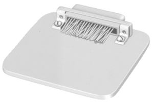
CONNECTOR SAVERITT CANNON MDM SERIES CONNECTOR SAVER Save wear and tear on your equipment and system connectors by using the "Connector Saver." The multi-matings and unmatings experienced by most connectors during testing and final check out can be eliminated. Simply mate the Connector Saver to your unit and use the opposite side for your testing interface... less wear, less tear, less chance of damage. It is available in all eight standard MDM layouts. Mating hardware is available and can be ordered either separately or included with the Connector Saver. Typical MDM style connections have a minimum mating cycle life of 500 matings. By using up to 500 Connector Savers, equipment mating life can be extended 500 times. 500 mates x 500 Connector Savers = 250,000 matings before you would need to replace/repair the original connector on the piece of equipment.
A174 Electroless Nickel Size With Hardware W/O Hardware *Hardware Kits A Max. B ±.005 (0.13) C Max. 9 MDM98479-86 MDM98479-18 320-9505-014** .785 (19.94) .565 (14.35) .308 (7.82) 15 MDM98479-87 MDM98479-19 320-9505-014** .935 (23.75) .715 (18.16) .308 (7.82) 21 MDM98479-88 MDM98479-20 320-9505-014** 1.085 (27.56) .865 (21.97) .308 (7.82) 25 MDM98479-89 MDM98479-21 320-9505-014** 1.185 (30.10) .965 (24.51) .308 (7.82) 31 MDM98479-90 MDM98479-14 320-9505-014** 1.335 (33.91) 1.115 (28.32) .308 (7.82) 37 MDM98479-91 MDM98479-15 320-9505-014** 1.485 (37.72) 1.265 (32.13) .308 (7.82) 51 MDM98479-92 MDM98479-16 320-9505-014** 1.435 (36.45) 1.215 (30.86) .351 (8.91) 100 MDM98479-93 MDM98479-17 320-9508-014*** 2.170 (55.12) 1.800 (45.72) .394 (10.01) * Kit contains 2 bushings-jackpost/jackscrew and 2 E-rings. ** Size 9-51 - #2-56 UNC-2B Thread *** Size 100 - #4-40 UNC-2B Thread All dimensions are shown in inches (millimeters in parentheses) JACKPOST BUSHINGITT CANNON MDM SERIES JACKPOST BUSHING (FOR REAR PANEL MOUNTING FOR SIZES 9-51)
Jackpost Kit Number* Panel Thickness 320-9505-007 3/32 (2.4) 320-9505-006 1/16 (1.6) 320-9505-005 3/64 (1.2) 320-9505-004 1/32 (0.8) * A kit consists of 2 jackposts, 2 nuts, 2 washers ITT CANNON MDM SERIES PLUG & RECEPTACLE PANEL CUTOUT DIMENSIONS
Shell Size A +.004 (0.10) .000 (0.00) B +.004 (0.10) .000 (0.00) C ± .005 (0.13) 9 .401 (10.19) .252 (6.40) .565 (14.35) 15 .551 (14.00) .252 (6.40) .715 (18.16) 21 .701 (17.81) .252 (6.40) .865 (21.97) 25 .801 (20.34) .252 (6.40) .965 (24.51) 31 .951 (24.16) .252 (6.40) 1.115 (28.34) 37 1.101 (27.97) .252 (6.40) 1.265 (32.13) 51 1.051 (26.70) .295 (7.49) 1.215 (30.86) Dimensions are shown in inches (millimeters in parentheses) MOUNTING HARDWAREITT CANNON MDM SERIES MOUNTING HARDWARE VIEWS (FOR SIZES 9-51) This hardware is factory-installed.
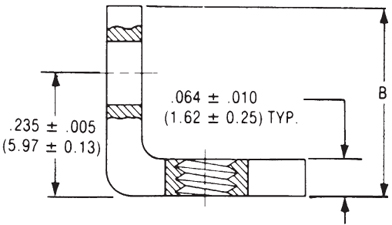
Part Number Description A ± .005 (±0.13) B Max. 322-9500-000 Screw Lock Assemby N/A 320-9505-000 Jackpost Kit N/A 015-9516-002 Mounting Bracket 90º MDM for 9 through 37 Shell Sizes .147 (3.73) .308 (7.82) 015-9516-003 Mounting Bracket 90º MDM for 51 Shell Sizes .169 (4.29) .350 (8.89) NOTES: Screw lock assembly (322-9500-000) can be used for front mounting only. Jackpost kit (320-9505-000) consists of two assemblies, shipped unassembled.
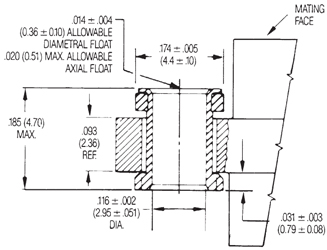
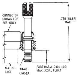
Shown here is a cutaway view of the float mount for the MDM connector. The basic shell dimensions are the same for the float mount and the screw mounting hole configurations. View shown is for standard float mount front panel mounting. Reverse mounting is available on request. ITT CANNON MDM SERIES MOUNTING HARDWARE TO MILITARY SPECIFICATIONS (FOR SIZES 9-100) PER MIL-DTL-83513/05
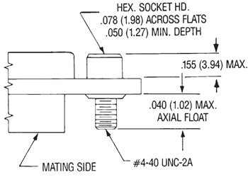
Figure 1. Figure 2. Figure 3. Allen Head To order hardware kits separately, order either by M83513/05-** or by 320-950X-XXX. Size 9-51 Size 100 Description Mod Code Part Number Mil # Mod Code Part Number Mil # Slotted Head Jackscrew Assy Low Profile (Figure 1) M5 320-9508-025 M83513/05-05 M15 320-9508-021 M83513/05-15 Slotted Head Jackscrew Assy High Profile (Figure 2) M6 320-9508-027 M83513/05-06 M16 320-9508-023 M83513/05-16 Allen Had Jackscrew Assy Low Profile (Figure 1) M2 320-9508-026 M83513/05-02 M12 320-9508-022 M83513/05-12 Allen Had Jackscrew Assy High Profile (Figure 2) M3 320-9508-028 M83513/05-03 M13 320-9508-024 M83513/05-13 Jackpost Assy (Figure 3) M7 320-9508-033 M83513/05-07 M17 320-9508-030 M83513/05-17 *Size 100 requires B1 size mounting holes ITT CANNON MDM SERIES MOUNTING HARDWARE VIEWS FOR SIZE 100
This hardware is supplied unassembled. 320-9505-015 015-9528-000
ITT CANNON MDM SERIES PRE-INSTALLED HARDWARE
This hardware is factory-installed.
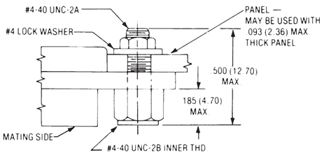
*Note: Torque values are as follows: Low Profile Jackscrew (L)-4.0 in/lbs. Standard Jackscrew (K)-4.0 in/lbs. ITT CANNON MDM SERIES JACKPOST BUSHING FOR REAR PANEL MOUNTING
Jackpost Kit Number* Panel Thickness 320-9505-013 3/32 (2.4) 320-9505-012 1/16 (1.6) 320-9505-010 1/32 (0.8) 320-9505-011 3/64 (1.2) Dimensions for Rear Panel Mountings Dimensions are shown in inches (millimeters in parentheses) |
Philadelphia
19116
Click here for the contact information of the branch nearest you.


