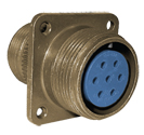
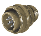
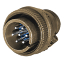
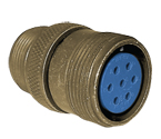
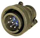
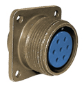
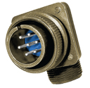
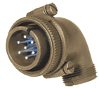
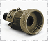
Amphenol 97 Series Connectors
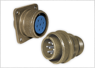
MATES WITH ALL THREADED COMMERCIAL SAE-AS50151 (MIL-DTL-5015) CONNECTORS
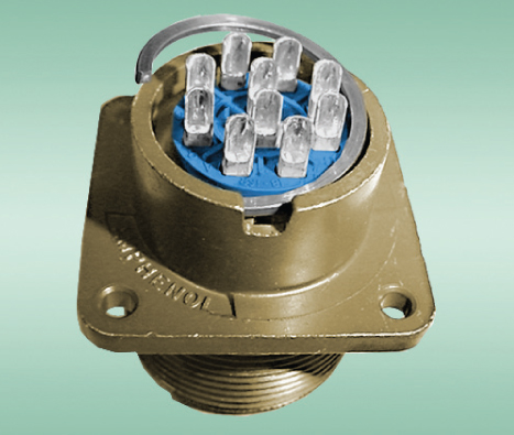
Amphenol 97 series connectors are a durable, cost-effective commercial SAE-AS50151 (MIL-DTL-5015) connector available in a variety of shell styles, sizes, contacts, and layouts. Contacts are silver-plated with pre-tinned solder cups. These Amphenol 97 series connectors are excellent for industrial applications including robotics, machine tools and welding. For full product information on Amphenol 97 series connectors, please see the specifications below.
Get shopping! Amphenol 97 series connector industrial prefixes include 97-3100A, 97-3102A, 97-3106A and 97-3108B.
|
FEATURESAMPHENOL 97 SERIES FEATURES
MATERIALS & FINISHESAMPHENOL 97 SERIES MATERIALS & FINISHES
Shell Aluminum alloy
Shell Plating Olive Drab Chromate, Clear Chromate Coating over Cadmium Plating to QQ-P-416, Black Alloy, Conductive Black Alloy, Electroless Nickel, Green Zinc, Gray Zinc Nickel
Contacts Brass or copper alloy
Contacts Platings Silver plating to ASTM B700 (solder contacts have tinned solder pot) gold plating to ASTM B488
Insulator Diallyl phthalate (blue color)
ELECTRICAL DATAAMPHENOL 97 SERIES ELECTRICAL DATA
Operating Voltage/Test VoltageSuggested Operating Voltage Air Spacing Creepage Distance Nom. Service Rating* Test Voltage (RMS) DC AC (RMS) IN. MM. IN. MM. I 1,000 250 200 1/32 0.79 1/16 1.59 A 2,000 700 500 1/16 1.59 1/8 3.18 D 2,800 1,250 900 1/8 3.18 3/16 4.76 E 3,500 1,750 1,250 3/16 4.76 1/4 6.35 B 4,500 2,450 1,750 1/4 6.35 5/16 7.94 C 7,000 4,200 3,000 5/16 7.94 1 25.4 * Each insulator has a specific rating. These numbers should be used by the designer only as a guide. The Service Ratings for each layout are listed here. 97 series connectors show no evidence of breakdown when the given test voltages are applied between the two closest contacts and between the shell and the contacts closest to the shell for a period of one minute, per MIL-STD-1344 Method 3001. Current Rating & Contact Resistance Contact Size Test Current (Amps) Potential Drop (Millivolts) 16 13 49 12 23 42 8 46 26 4 80 23 0 150 21 Maximum total current to be carried per connector in wire bundles as specified in MIL-W-5088. Contact resistance when tested to MIL-C-39029 will not exceed voltage drops listed in above table. MECHANICALAMPHENOL 97 SERIES MECHANICAL
Wire Range Sizes 26 to 0 AWG
Contact Resistance
Insulation Resistance > 5,000 megohms at 77°F (25°C) per MIL-DTL-5015, 3.18
Mating Life 100 cycles minimum per MIL-DTL-5015, 3.16
Salt Spray MIL-STD-1344 Method 1001 Condition B minimum (Cadmium) 48 hour, Gray Zinc Nickel 500 hours
Heat +257˚F (+125˚C) for 60 hours, +185˚F (+85˚C) for 1,000 hours per MIL-DTL-5015, 4.6.14, minimum
Chemical Resistance 20-hour full immersion (unmated) in hydraulic fluid and lubricating oil per MIL-DTL-5015 minimum
Vibration 10 to 2,000Hz (15g’s) 10 microseconds maximum discontinuity to MIL-STD-1344 Method 2005 per MIL-DTL-5015
Shock 50g 11 millisecond duration, three major axes 10 microseconds maximum discontinuity to MIL-DTL-5015, 3.13
Contact Type Solder (hard silver or gold plating), High Voltage
Number of Circuits
Contact Retention and seperation forces to MIL-DTL-5015, 4.6.6 & 3.26 minimum. Retention Axial Load Separation Force Minimum Contact Size Newtons Lbs. Newtons Lbs. 16 44 10 1 0.25 12 67 15 2 0.5 8 89 20 3 0.75 4 89 20 4 1 0 111 25 9 2 Polarization Integral key and keyway plus optional rotational polarization.Click here for valid rotations.
Approvals/Agency Listing UL# EII5497; CSA LR69183 for 97 Series
COMPONENTSAMPHENOL 97 SERIES COMPONENTS
|
|
AMPHENOL 97 SERIES APPLICATIONS
Industrial, commercial and medical applications where cost-effective, general-duty connectors are required.
|
|
STEP 1: SHELLAMPHENOL 97 SERIES EXAMPLE
STEP 1 2 3 4 5 97 3106A 18-1 P -946 SERIES PREFIX SHELL STYLE LAYOUT CONTACT ROTATION PLATING STEP 1: SELECT SHELL STYLE, PLUG OR RECEPTACLE
97-3100A 97-3106A 97-3106B
97-3101A 97-3107A 97-3107B
97-3102A 97-3108A 97-3108B STEP 2: LAYOUTSTEP 2: SELECT LAYOUT
Click here for more information. 8S-1 16S-4 18-4 18-30 20-27 22-22 24-24 28-21 10SL-3* 16S-5 18-5 18-31 20-29 22-23 24-25 32-5 10SL-4* 16S-6 18-8 18-420 20-30 22-27 24-26 32-6 12-5 16S-8 18-9 20A16 20-32 22-28 24-27 32-7 12S-2 16S-14 18-10 20A37 20-33 22-30 24-28 32-8 12S-3 16S-15 18-11 20-3 22-1 22-31 28-1 32-17 12SL-844 16S-16 18-12 20-4 22-2 22-32 28-2 32-414 12-5 16S-17 18-13 20-6 22-4 22-34 28-3 36-1 14S-1 16SA18 18-16 20-7 22-5 24-2 28-6 36-5 14S-2 16SA19 18-17 20-8 22-8 24-5 28-8 36-6 14S-4 16SA20 18-18 20-11 22-9 22-6 28-9 36-7 14S-5 16SA21 18-19 20-14 22-10 24-7 28-10 36-8 14S-6 16-7 18-20 20-15 22-11 24-9 28-11 36-9 14S-7 16-9 18-22 20-16 22-12 24-10 28-12 36-10 14S-9 16-10 18-23 20-17 22-13 24-11 28-13 36-11 14S-10 16-11 18-24 20-18 22-14 24-12 28-15 36-12 14S-11 16-12 18-25 20-19 22-15 24-16 28-16 36-15 14S-12 16-13 18-26 20-21 22-16 24-19 28-17 36-403 14S-13 18A31 18-27 20-23 22-18 24-20 28-18 14S-14 18-1 18-28 20-24 22-19 24-21 28-19 16S1 18-3 18-29 20-25 22-20 24-22 28-20 * Socket for plug only. Pin for receptacle only. STEP 5: PLATINGSTEP 5: SELECT PLATING


CONTACTS SHELL PLATING OTHER MODIFIERS 426 = Gold over Silver 621 = Black Alloy 417 = Plug Seal O-Ring 431 = Less Pre-filed Solder Cups 639 = Clear Chromate over Cadmium 438 = Plug Seal O-Ring and Potting Cup 640 = Conductive Black Alloy 940 = Add Cable Clamp and Bushing 689 = Electroless Nickel 946 = 431+621 Mod Codes Combined (RoHS) 958=Gray Zinc Nickel 947 = 431+689 Mod Codes Combined (RoHS) 955 = 431+640 Mod Codes Combined (RoHS) 959 = 431 + 958 Mod Codes Combined (RoHS) NEED HELP? PEI engineers will help you solve your design challenges and build the perfect part for your application. Email us at [email protected] or complete our online Technical Request at www.peigenesis.com/en/technical-support. To contact us by phone, click here for a complete listing of our branch offices and contact numbers. |
|
RECEPTACLE STYLESAMPHENOL 97 SERIES RECEPTACLE STYLES
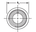
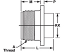
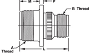
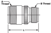
97-3100A/97-3102A 97-3102A 97-3100A 97-3101A 97-3100A/97-3101A Shell Size M P R S T A Thread L KK L S1 L B Thread 2A 8S 0.56 0.078 0.59 0.88 0.120 1/2-28 0.859 0.438 1.25 0.88 1.25 .5000-28 UNEF 10S 0.56 0.078 0.72 1.00 0.120 5/8-24 0.859 0.500 1.313 1.00 1.313 .5000-28 UNEF 10SL 0.56 0.078 0.72 1.00 0.120 5/8-24 0.953 0.688 1.281 1.00 1.281 .6250-24 UNEF 12S 0.56 0.078 0.81 1.09 0.120 3/4-20 0.969 0.688 1.469 1.09 1.469 .6250-24 UNEF 12 0.75 0.078 0.81 1.09 0.120 3/4-20 1.328 0.688 1.84 1.09 1.84 .6250-24 UNEF 12SL 0.56 0.078 0.81 1.09 0.120 3/4-20 0.844 0.688 - 1.09 - .6250-24 UNEF 14S 0.56 0.078 0.91 1.185 0.120 7/8-20 0.953 0.750 1.469 1.16 1.469 .7500-20 UNEF 16S 0.56 0.078 0.97 1.28 0.120 1-20 0.953 0.875 1.469 1.28 1.469 .8750-20 UNEF 16 0.75 0.125 0.97 1.28 0.120 1-20 1.375 0.875 1.891 1.28 1.891 .8750-20 UNEF 18 0.75 0.125 1.06 1.38 0.120 1 1/8-18 1.375 1.000 1.984 1.38 1.984 .8750-20 UNEF 18 0.75 0.125 1.06 1.38 0.120 1 1/8-18 1.375 1.000 1.984 1.38 1.984 1.000-20 UNEF 20 0.75 0.125 1.16 1.50 0.120 1 1/4-18 1.375 1.125 1.891 1.50 1.891 1.1875-18 UNEF 22 0.75 0.125 1.25 1.63 0.120 1 3/8-18 1.375 1.250 1.984 1.63 1.984 1.1875-18 UNEF 24 0.81 0.125 1.38 1.75 0.147 1 1/2-18 1.375 1.375 2.25 1.75 2.25 1.4375-18 UNEF 28 0.81 0.125 1.56 2.00 0.147 1 3/4-18 1.375 1.625 2.25 2.00 2.25 1.4375-18 UNEF 32 0.88 0.125 1.75 2.25 0.173 2-18 1.469 1.906 2.375 2.25 2.375 1.7500-18 UNS 36 0.88 0.125 1.94 2.50 0.173 2 1/4-16 1.469 2.125 2.375 2.50 2.375 2.0000-18 UNS All dimensions in inches (millimeters in parentheses) PLUG STYLESAMPHENOL 97 SERIES PLUG STYLES (BARREL ASSEMBLIES) AMPHENOL 97 SERIES ENDBELL STYLES
97-3106B
97-3108B
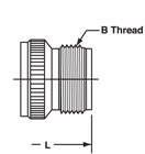
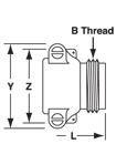
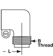
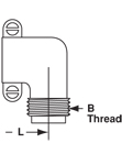
97-3108B 97-3106 97-3106A 97-3106B/97-3107B 97-3108A 97-3108B Shell Q L L Y Z L L B THREAD 2A 8S 0.75 1.25 - - - - - .5000-28 UNEF 10S 0.88 1.31 - - - 1.25 1.38 .5000-28 UNEF 10SL 0.88 1.38 - - - 1.31 1.50 .6250-24 UNEF 10SL 0.88 1.38 - - - 1.31 1.50 .6250-24 UNEF 12S 1.00 1.47 - - - 1.38 1.56 .6250-24 UNEF 12 1.00 1.84 - - - 1.22 1.88 .6250-24 UNEF 12SL 1.00 - - - - 1.38 - .7500-20 UNEF 14S 1.13 1.47 1.69 1.16 1.13 1.22 1.72 .7500-20 UNEF 16S 1.25 1.47 1.69 1.25 1.25 1.50 1.75 .8750-20 UNEF 16 1.25 1.89 - - - 1.94 2.13 .8750-20 UNEF 18 1.34 1.98 2.19 1.64 1.34 1.94 2.16 1.0000-20 UNEF 20 1.47 1.89 2.13 1.81 1.47 2.06 2.38 1.1875-18 UNEF 22 1.59 1.98 2.13 1.94 1.59 2.06 2.41 1.1875-18 UNEF 24 1.72 2.25 2.28 2.06 1.72 2.47 2.63 1.4375-18 UNEF 28 1.97 2.25 2.28 2.31 1.97 2.47 2.63 1.4375-18 UNEF 32 2.22 2.38 2.31 2.59 2.22 - 2.81 1.7500-18 UNS 36 2.47 2.38 2.34 2.84 2.47 - 2.84 2.0000-18 UNS All dimensions in inches (millimeters in parentheses) PANEL CUTOUTSAMPHENOL 97 SERIES PANEL CUTOUTS
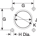
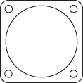
FLANGE STYLE 0-2-6B
Mounting Hole Diameter
8S 0.594 (15.1) 0.134 (3.4) 0.396 (10.1) 0.603 (15.4) 10S/10SL 0.717 (18.2) 0.134 (3.4) 0.646 (16.4) 0.728 (18.5) 12S/12SL/12 0.811 (20.6) 0.134 (3.4) 0.646 (16.4) 0.854 (21.7) 14S 0.906 (23.0) 0.134 (3.4) 0.776 (19.7) 0.980 (24.9) 16S/16 0.969 (24.6) 0.134 (3.4) 0.902 (22.9) 1.091 (27.7) 18 1.063 (27.0) 0.134 (3.4) 1.028 (26.1) 1.224 (31.1) 20 1.157 (29.4) 0.134 (3.4) 1.161 (29.5) 1.358 (34.5) 22 1.252 (31.8) 0.134 (3.4) 1.287 (32.7) 1.488 (37.8) 24 1.374 (34.9) 0.154 (3.4) 1.417 (36.0) 1.358 (41.3) 28 1.563 (39.7) 0.154 (3.4) 1.654 (42.0) 1.854 (47.1) 28 1.563 (39.7) 0.154 (3.4) 1.654 (42.0) 1.854 (47.1) 32 1.752 (44.5) 0.177 (4.5) 1.902 (48.3) 2.118 (53.8) 36 1.937 (49.2) 0.177 (4.5) 2.150 (54.6) 2.362 (60.0) 40 2.185 (55.5) 0.177 (4.5) 2.409 (61.2) 2.610 (66.3)
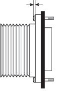
PANEL THICKNESSAMPHENOL 97 SERIES PANEL THICKNESS
Max Screwhead Shell Size Front Mount Rear Mount 8SL 10S 10SL 12S/12SL 12 14S 16S 16 18 20 22 24 28 32 36 40
.125 (3.18) .125 (3.18) .125 (3.18) .125 (3.18) .187 (4.75) .187 (4.75) .187 (4.75) .187 (4.75) .187 (4.75) .187 (4.75) .187 (4.75) .187 (4.75) .187 (4.75) .250 (6.35) .250 (6.35) .250 (6.35)
|
|
MS3057-AAMPHENOL 97 SERIES M3057-A CABLE CLAMP
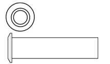
Standard MS3057 cable clamps have dual-clamping action to provide a balanced, positive hold on the wires and greatly reduce moisture transmission. This cable clamp accepts MS3420 bushings. MS3420 bushings can be nested to reduce the inside diameter to more closely match the diameter of the cable or wire bundle. Standard Clamp Standard Clamp and Telescopic Bushing Shell Size Thread Low-Cost Cast Zinc Aluminum Aluminum Maximum Cable Diameter Low-Cost Zinc With Bushing Bushing Included Bushing ID Inch (MM) 8S/10S 1/2-28 UNEF - MS3057-3A M85049/41-3A 0.250 (6.35) - MS3420-3 0.130 (3.3) 12/12S/10SL 5/8-24 UNEF **97-3057-1004 MS3057-4A M85049/41-4A 0.312 (7.92) 97-3057-1004-1 MS3420-4 0.220 (5.6) 12SL/14S 3/4-20 UNEF **97-3057-1007 MS3057-6A M85049/41-6A 0.438 (11.10) 97-3057-1007-1 MS3420-6 0.312 (7.9) 16/16S 7/8-20 UNEF **97-3057-1008 MS3057-8A M85049/41-8A 0.562 (14.27) 97-3057-1008-1 MS3420-8 0.437 (11.1) 18 1-20 UNEF **97-3057-1010 MS3057-10A M85049/41-10A 0.625 (15.88) 97-3057-1010-1 MS3420-10 0.562 (14.3) 20/22 1 3/16-18 UNEF **97-3057-1012 MS3057-12A M85049/41-12A 0.750 (19.0) 97-3057-1012-1 MS3420-12 0.625 (15.9) 24/28 1 7/16-18 UNEF **97-3057-1016 MS3057-16A M85049/41-16A 0.938 (23.80) 97-3057-1016-1 MS3420-16, -12 0.625 (15.9) 32 1 3/4-18 UNS **97-3057-1020 MS3057-20A M85049/41-20A 1.250 (31.75) 97-3057-1020-1 MS3420-20, -16 0.750 (19.0) 36 2-18 UNS **97-3057-1024 MS3057-24A M85049/41-24A 1.375 (34.92) 97-3057-1024-1 MS3420-24, -20 0.937 (23.8) 40 2 1/4-16 UNS - MS3057-28A M85049/41-28A 1.625 (41.28) - - - Default is CAD OD MS3057-CAMPHENOL 97 SERIES MS3057-C WATERPROOF CABLE CLAMP
Wire Diameter Optional Bushings Shell Size Part Number Max. Min. Part Number Max. Wire Dia. 8S/10S MS3057-3C 0.219 (5.56) 0.095 (2.41) MS3420-3A 0.125 (3.17) 10SL/12/12S MS3057-4C 0.312 (7.93) 0.188 (4.80) MS3420-4A 0.219 (5.56) 12SL/14S MS3057-6C 0.438 (11.12) 0.281 (7.10) MS3420-6A 0.312 (7.93) 16/16S MS3057-8C 0.530 (13.48) 0.312 (7.90) MS3420-8A 0.438 (11.10) 18 MS3057-10C 0.625 (15.87) 0.375 (9.50) MS3420-10A 0.438 (11.10) 20/22 MS3057-12C 0.750 (19.00) 0.500 (12.70) MS3420-12A 0.540 (13.74) 24/28 MS3057-16C 0.940 (23.80) 0.625 (15.90) MS3420-16A 0.750 (19.00) 32 MS3057-20C 1.25 (31.75) 0.921 (23.40) MS3420-20A 0.938 (23.80) 36 MS3057-24C 1.38 (35.00) 1.00 (25.40) MS3420-24A 1.12 (28.50) 40 MS3057-28C 1.62 (41.25) 1.25 (31.80) MS3420-28A 1.125 (31.75) MS3420AMPHENOL 97 SERIES MS3420 TELESCOPING BUSHINGS
Shell Size First Bushing Part Number Inside Diameter 2nd Nested Bushing Inside Diameter Fits in Cable Clamp 8S/10S MS3420-3 .130 (3.30) NONE - MS3057-3A 10SL MS3420-4 .220 (5.59) NONE - MS3057-4A 12/12S MS3420-4 .220 (5.59) NONE - MS3057-4A 14S MS3420-6 .312 (7.92) NONE - MS3057-6A 16S MS3420-8 .437 (11.10) NONE - MS3057-8A 16 MS3420-8 .437 (11.10) NONE - MS3057-8A 18 MS3420-10 .562 (14.30) NONE - MS3057-10A 20 MS3420-12 .625 (15.90) NONE - MS3057-12A 22 MS3420-12 .625 (15.90) NONE - MS3057-12A 24 MS3420-16 .750 (19.05) MS3420-12 .625 (15.90) MS3057-16A 28 MS3420-16 .750 (19.05) MS3420-12 .625 (15.90) MS3057-16A 32 MS3420-20 .937 (23.80) MS3420-16 .750 (19.05) MS3057-20A 36 MS3420-24 1.250 (31.75) MS3420-20 .937 (23.80) MS3057-24A 40 MS3420-28 1.375 (34.92) MS3420-24 1.250 (31.75) SE96-28A4 All Dimensions in Inches (millimeters in parentheses) MS3420-AAMPHENOL 97 SERIES MS3420-A REDUCTION BUSHINGS
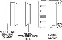
For use with MS3057-C cable clamps (style-C) to reduce the wire sealing diameter. Bushings can be nested, one inside the other, to progressively reduce the inside diameter of the cable clamp. The column labeled “reduction bushings” shows the acceptable nesting options for each clamp. 9767AMPHENOL 97 SERIES 9767 CABLE CLAMPS
Max. Cable Outside Diameter Min. Cable Outside Diameter
Cable Clamp Part Number
Thread Class 2B UNEF 10SL/12S/12 9767-12-4 0.219 5.55 0.100 2.54 5/8-24 12SL/14S 9767-14-4 0.219 5.55 0.100 2.54 3/4-20 12SL/14S 9767-14-6 0.344 8.73 0.176 4.47 3/4-20 16S/16 9767-16-4 0.219 5.55 0.100 2.54 7/8-20 16S/16 9767-16-6 0.344 8.73 0.176 4.47 7/8-20 16S/16 9767-16-8 0.438 11.12 0.177 4.50 7/8-20 18 9767-18-6 0.344 8.73 0.176 4.47 1-20 18 9767-18-8 0.438 11.12 0.177 4.50 1-20 18 9767-18-10 0.563 14.29 0.292 7.42 1-20 20/22 9767-22-8 0.438 11.12 0.177 4.50 1-3/16-18 20/22 9767-22-10 0.563 14.29 0.292 7.42 1-3/16-18 20/22 9767-22-12 0.688 17.46 0.370 9.40 1-3/16-18 24/28 9767-28-10 0.563 14.29 0.292 7.42 1-7/16-18 24/28 9767-28-12 0.688 17.46 0.370 9.40 1-7/16-18 24/28 9767-28-16 0.844 21.43 0.536 13.61 1-7/16-18 32 9767-32-20 1.031 26.19 0.590 14.99 1-3/4-18UNS 36 9767-36-16 0.844 21.43 0.536 13.61 2-18UNS All dimensions in inches (millimeters in parentheses) GASKETSAMPHENOL 97 SERIES GASKETS
Synthetic rubber gaskets are used to ensure a moisture-tight seal between a receptacle and the panel. Gaskets are available for front or rear panel mounting of style 3100 and 3102 connectors. Gasket thickness is approximately .031 inches (1 mm) for nonconductive and low-temperature types. Shell Size Non-Conductive Conductive Low-Temperature-67ºF (-55ºC) 8S 10-040450-008 10-040450-08S 10-036675-008 10S/10SL 10-040450-010 10-040450-10S 10-036675-010 12/12S 10-040450-012 10-040450-12S 10-036675-012 14S 10-040450-014 10-040450-14S 10-036675-014 16S 10-040450-016 10-040450-16S 10-036675-016 16 10-040450-016 10-040450-16S 10-036675-016 18 10-040450-018 10-040450-18S 10-036675-018 20 10-040450-020 10-040450-20S 10-036675-020 22 10-040450-022 10-040450-22S 10-036675-022 24 10-040450-024 10-040450-24S 10-036675-024 28 10-040450-028 10-040450-28S 10-036675-028 32 10-040450-032 10-040450-32S 10-036675-032 36 10-040450-036 10-040450-36S 10-036675-036 40 10-040450-040 10-040450-40S 10-036675-040 All dimensions in inches (millimeters in parentheses) METAL DUST CAPSAMPHENOL 97 SERIES METAL DUST CAPS WITH SASH CHAIN & DUMMY RECEPTACLES
Metal dust caps are used to protect the contacts when the connectors are left unmated. Dust caps come with metal chain lanyards. Dust Caps Dust Caps Dummy Receptacles
8S MS25042-8* MS25043-8* MS3105-8S 10S/10SL MS25042-10* MS25043-10* MS3105-10S 12/12S/12SL MS25042-12* MS25043-12* MS3105-12S 14S MS25042-14* MS25043-14* MS3105-14S 16S MS25042-16* MS25043-16* MS3105-16S 16 MS25042-16* MS25043-16* MS3105-16 18 MS25042-18* MS25043-18* MS3105-18 20 MS25042-20* MS25043-20* MS3105-20 22 MS25042-22* MS25043-22* MS3105-22 24 MS25042-24* MS25043-24* MS3105-24 28 MS25042-28* MS25043-28* MS3105-28 32 MS25042-32* MS25043-32* MS3105-32 36 MS25042-36* MS25043-36* MS3105-36 40 MS25042-40* MS25043-40* MS3105-40 *Contact us for all other platings *D = Olive drab chrome over cadmium DA = Anodized |
|
AMPHENOL 97 SERIES ASSEMBLY INSTRUCTIONS
READ THESE INSTRUCTIONS PRIOR TO ASSEMBLY.
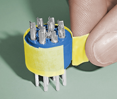
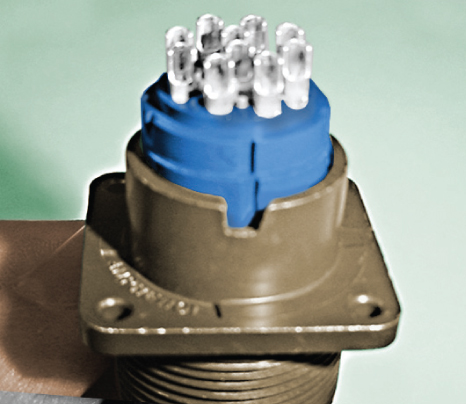
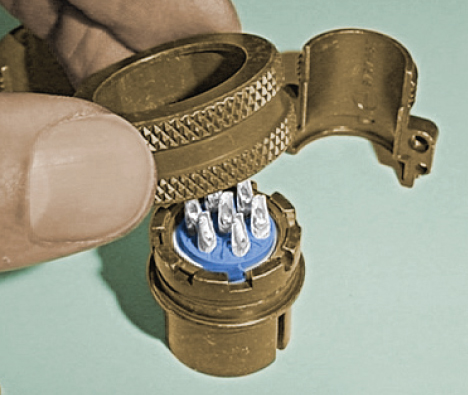
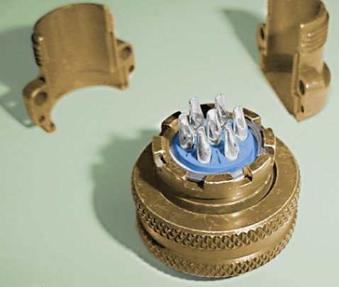
STEP 1: Open both shell kit and insert kit. STEP 2: Remove yellow tape from insert, being careful not to allow front and rear insulators to come apart. STEP 3: Insert insulator assembly into shell or barrel, aligning the key and keyway until rear of the insert is positioned just below the retaining spring ring ridge.
STEP 4: Insert the retainer spring ring into the ridge by working one end in first, then working around the ring until it snaps into place. STEP 5: For barrels, add coupling nut to barrel and slide rear accessories on to cable. STEP 6: Solder wires onto proper contacts.
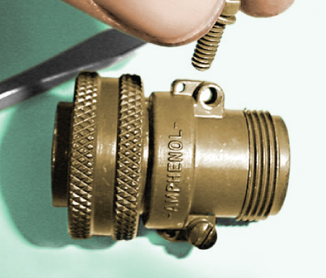
STEP 7: Thread endbell onto barrel/ shell. Slide cable clamp down the cable and thread onto the endbell. Tighten endbell and cable clamp using endbell accessory tools. STEP 8: Tighten cable clamp screws appropriately for the specific wire/cable in use. |
Philadelphia
19116
Click here for the contact information of the branch nearest you.


