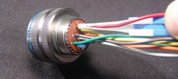
Amphenol MS3450 Connectors (MIL-DTL-5015)
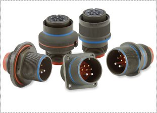
HIGH-PERFORMANCE ALTERNATIVE TO OLDER MIL-DTL-5015 SOLDER TYPES
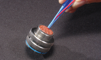
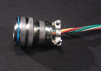
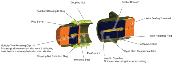
The Amphenol MS3450 MIL-DTL-5015 Rear-Release Threaded (Matrix®) series connectors use rear-release crimp contacts with a retention clip. These Amphenol MS3450 connectors fill the gap between older MIL-DTL-5015s and the environmental and higher-performance needs of new technologies. These MS3450 connectors are sealed to withstand moisture, condensation, vibration and flash-over. Over 165 contact layouts are available, in variations that allow for just power, just signal, or a mix of both contact types. These were formerly MIL-C-5015. For more detailed product information on MS3450 series connectors, please see the specifications below.
Get shopping! Mil spec part number prefixes include MS3450, MS3451, MS3452, MS3454, MS3456 and MS3459.
|
FEATURES
AMPHENOL MS3450 SERIES FEATURES
MATERIALS & FINISHESAMPHENOL MS3450 SERIES MATERIALS & FINISHES
Shell Aluminum alloy, stainless steel
Shell Plating Cadmium, Anodized, Electroless Nickel, Zinc Alloy, or Passivated
Contacts Copper alloy
Contact Plating Silver or Gold
Insulator Neoprene
Seals Silicone
ELECTRICAL DATAAMPHENOL MS3450 SERIES ELECTRICAL DATA
Operating Voltage/Test Voltage
Standard Sea Level Conditions Pressure Altitude† 50,000 Feet Pressure Altitude† 70,000 Feet MS Service Rating Airspace Creepage DC V AC VRMS Minimum Flashover Voltage AC (RMS) Test Voltage AC (RMS) Minimum Flashover Voltage AC (RMS) Test Voltage AC (RMS) Minimum Flashover Voltage AC (RMS) Test Voltage AC (RMS) I 1/32 1/16 250 200 1,400 1,000 550 400 325 260 A 1/16 1/8 700 500 2,800 2,000 800 600 450 360 D 1/8 3/16 1,250 900 3,600 2,800 900 675 500 400 E 3/16 1/4 1,750 1,250 4,500 3,500 1,000 750 550 440 B 1/4 5/16 2,450 1,750 5,700 4,500 1,100 825 600 480 C 5/16 1 4,200 3,000 8,500 7,000 1,300 975 700 560 * Each insulator has a specific service rating. These numbers should be used by the designer only as a guide. The Service Ratings for each layout are listed on here. † Not corrected for change in density resulting from variations in temperature. MS connectors show no evidence of breakdown when the given test voltages are applied between the two closest contacts and between the shell and the contacts closest to the shell for a period of one minute, per MIL-STD-1344 Method 3001. Current Rating & Contact Resistance Contact Size Test Current (Amps) Potential Drop (Millivolts) Contact Resistance (Milliohm) Max. 16 13 50 6 12 23 50 3 8 46 29 1 (0.44*) 4 80 14 0.5 (0.23*) 0 150 12 0.2 (0.18*) *Using non-military crimp Radsok contact Maximum total current to be carried per connector in wire bundles as specified in MIL-W-5088. Contact resistance when tested to MIL-C-39029 will not exceed voltage drops listed in above table. Wire Range Sizes 20 AWG - 0 AWG
Insulation Resistance 50,000 megohms minimum at 77°F (25°C)
1,000 megohm minimum at 392°F (200°C) Class L and 347°F (175°C) Class W MECHANICALAMPHENOL MS3450 SERIES MECHANICAL
Operating Classes L, LS and KS -75°F to 392°F (-55°C to +200°C)
Temperature classes W and KT -75°F to 347°F (-55°C to 175°C) Wire Sealing Range Contact Size Wire Sealing Range Min. Wire Sealing Range Max. 16/16S 0.053 (1.35) 0.103 (2.62) 12 0.085 (2.16) 0.158 (4.01) 8 0.132 (3.35) 0.255 (6.48) 4 0.237 (6.02) 0.370 (9.40) 0 0.360 (9.14) 0.550 (13.97) Insulation Strip Length Contact Size Strip Length 16/16S .245 (6.2) 12 .245 (6.2) 8 .465 (11.8) 4 .465 (11.8) 0 .540 (13.7) Mating Life 100 cycles minimum
Salt Spray Class L & W 48 hours unmated; 48 hours mated per MIL-STD-1344 method 1001 condition letter A, paragraph 4.6.13.2 of MIL-DTL-5015, Class LS, KT, KS 952 hours mated, 48 hours unmated per MIL-STD-1344, method 1001 condition letter D, paragraph 4.6.13.3 of MIL-DTL-5015
Heat Class L, LS & KS, +392°F (+200°C); Class W, KT, +347°F (+175°C)
Chemical Resistance 20-hour full-immersion unmated in hydraulic fluid and lubricating oil per MIL-DTL-5015 minimum
Vibration 10 to 2,000Hz (10g’s) 10 microseconds maximum discontinuity to MIL-STD-1344 Method 2005, condition II per MIL-DTL-5015
Shock 50g 11-millisecond duration, three major axes. 10 microseconds maximum discontinuity to MIL-DTL-5015 per MIL-STD-1344 method 2004, condition A, 3.13.
Contact Type Rear-release crimp
Number of Circuits 1 to 85
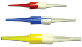
Contact Insertion & Extraction Insertion from rear of connector with simple plastic or high-quality metal hand tool. Extraction from rear with plastic or high-quality metal hand tools.
Contact Retention Per MIL-DTL-5015, 3.10 & 4.6.6.
Contact Size Axial Load Lbs. Min. 16 25 12 30 8 50 4 60 0 75 Polarization Integral key and keyway plus optional rotational polarization.
Approvals MIL-DTL-5015 (MIL-C-5015)
All dimensions in inches (millimeters in parentheses) |
|
AMPHENOL MS3450 SERIES APPLICATIONS
Military, industrial and commercial environments requiring extreme reliability, high-power handling and cost efficiency.
|
|
STEP 1: SHELLAMPHENOL MS3450 SERIES MILITARY PART NUMBER EXAMPLE
1 2 3 4 5 6 MS3450 L 18-11 P W -LC SHELL STYLE FINISH LAYOUT CONTACT POLARIZATION MODIFIER AMPHENOL MS3450 SERIES COMMERCIAL PART NUMBER EXAMPLE
1 2 3 4 5 6 9440 F 18-11 P W -190 SHELL STYLE FINISH LAYOUT CONTACT POLARIZATION MODIFIER STEP 1: SELECT SHELL STYLE, PLUG OR RECEPTACLE

Wall Mount
Cable Mount Receptacle
Standard Plug +
Plug with Self-locking
Box Mount Receptacle
Jam Nut Receptacle + + Most popular STEP 2: FINISHSTEP 2: SELECT FINISH
MILITARY COMMERCIAL L = Electroless Nickel A = Black Anodize W = Olive Drab Chromate over Cadmium F = Electroless Nickel LS = Stainless Steel Shell, Passivated W = Olive Drab Chromate over Cadmium KT** = Steel Shell, Olive Drab Chromate over Cadmium, Firewall FS = Stainless Steel Shell, Passivated KS** = Stainless Steel Shell, Passivated, Firewall KT =Steel Shell, Olive Drab Chromate over Cadmium, Firewall KS =Stainless Steel Shell, Passivated, Firewall ** KT and KS finishes are not QPLD for styles MS3451, MS3452 and MS35454 STEP 3: LAYOUTSTEP 3: SELECT LAYOUT (LISTED BY SHELL SIZE)
Click here for listing by # of contacts.
8S-1 16-12 20-14 22-27* 28-11 36-7 10S-2 16-13 20-15 22-30* 28-12 36-8 10SL-3 18-1 20-16 22-32* 28-13* 36-9 10SL-4 18-4 20-17 22-36* 28-15 36-10 12S-1* 18-5 S 20-18 24-2 28-16* 36-11* 12S-2* 18-6 S 20-19 24-4* 28-17 36-12 12S-3 18-7* 20-21 24-5 28-18* 36-15 12S-4 18-8 20-22 24-6* 28-19* 36-16* 12-5 18-9 20-24 24-7 28-20 36-17 14S-1 18-10 20-27 24-10 28-21 36-18* 14S-2 18-11 20-29 24-11 28-22 36-21* 14S-5 18-12 20-32* 24-12 32-1 36-52 14S-6 18-13 20-33 24-15* 32-2* 36-66 15S-7 18-14* 22-2 24-16* 32-3* 36-66 14S-9 18-15Δ 22-4 S 24-20 32-6 40-2* 14S-10* 18-16* 22-5 24-21* 32-7 40-3* 14S-11* 18-17* 22-6 24-22 32-9 40-4 14S-12 18-18* 22-7 P 24-24* 32-13 40-6* 14S-13* 18-19* 22-9* 24-27* 32-15 40-7* 14-3 18-22 22-10* 24-28 32-16* 40-9 16S-1 18-23* 22-11* 24-80* 32-17 40-56 16S-3* 18-24* 22-14 28-1 32-19* 40-62* 16S-4* 18-27* S 22-15* 28-2 32-20 16S-8 18-28* S 22-17* 28-3* 32-22* 16S-8 18-28* S 22-17* 28-3* 32-22* 16-2* 20-2 22-18* 28-4* 32-63 1 20-4 22-19 28-5* 32-73 16-9 20-7 22-21 28-8* 36-3 16-10 20-8 22-22 28-9 36-5 16-11 20-9* 22-23 28-10 36-6 *non-QPL, commercial only S = Tooled for sockets only P = Tooled for pins only Δ = QPL for pins only, sockets commercial only STEP 4: CONTACTSTEP 4: SELECT CONTACT

P = Pin STEP 5: POLARIZATIONSTEP 5: SELECT POLARIZATION

(Omit for normal) STEP 6: MODIFIERSTEP 6: SELECT MODIFIER

MILITARY & COMMERCIAL COMMERCIAL ONLY LC = Less Contacts 189 = E-nut M85049/31 190 = Straight strain relief 191 = 90 degree strain relief TIP: Make it easy! Order your connector, backshell and accessories with just one part number using our Cable Assembly Cookbook. See www.peigenesis.comindex.php?format=html&Itemid=903&option=com_content&view=category&layout=blog&id=161 |
|
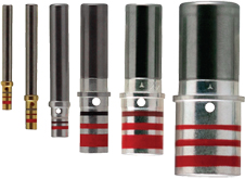
CONTACTSAMPHENOL MS3450 SERIES CONTACTS - PINS
Wire Strip Lengths
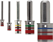
Contact Size 1 2 3 Min. Max. 16S 16, 18 & 20 M39029/29-212 Red Brown Red .245 (6.2) .053 (1.35) .103 (2.62) MS27488-16-3 Blue 16 16, 18 & 20 M39029/29-212 Red Brown Red .245 (6.2) .053 (1.35) .103 (2.62) MS27488-16-3 Blue 12 12 & 14 M39029/29-213 Red Brown Orange .245 (6.2) .085 (2.16) .158 (4.01) MS27488-12-3 Yellow 8 8 & 10 M39029/29-214 Red Brown Yellow .465 (11.8) .132 (3.35) .255 (6.48) MS27488-8-3 Red 4 4 & 6 M39029/29-215 Red Brown Green .465 (11.8) .237 (6.02) .370 (9.40) MS27488-4-3 Blue 0 0 & 2 M39029/29-216 Red Brown Blue .540 (13.7) .360 (9.14) .550 (13.97) MS27488-0-3 Yellow AMPHENOL MS3450 SERIES CONTACTS - SOCKETS
Wire Strip Lengths
Contact Size 1 2 3 Min. Max. 16S 16, 18 & 20 M39029/30-217 Red Brown Violet .245 (6.2) .053 (1.35) .103 (2.62) MS27488-16-3 Blue 16 16, 18 & 20 M39029/30-218 Red Brown Gray .245 (6.2) .053 (1.35) .103 (2.62) MS27488-16-3 Blue 12 12 & 1 4 M39029/30-219 Red Brown White .245 (6.2) .085 (2.16) .158 (4.01) MS27488-12-3 Yellow 8 8 & 10 M39029/30-220 Red Red Black .465 (11.8) .132 (3.35) .255 (6.48) MS27488-8-3 Red 4 4 & 6 M39029/30-221 Red Red Brown .465 (11.8) .237 (6.02) .370 (9.40) MS27488-4-3 Blue 0 0 & 2 M39029/30-222 Red Red Red .540 (13.7) .360 (9.14) .550 (13.97) MS27488-0-3 Yellow Thermocouples available, please contact us for information. All dimensions in inches (millimeters in parentheses) CONTACT TOOLSAMPHENOL MS3450 SERIES CONTACT TOOLS - PINS
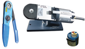
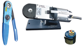
Metal Plastic Contact Size Hand-Crimp Tool Power-Crimp Tool Turret Heads Use Locator Color Insertion Tool Extraction Tool Insertion/Extraction Tool Insertion Tip Color Extraction Tip Color 16S M22520/1-01 WA27F M22520/1-02 Blue DAK83-16B DRK83-16B M81969/14-03 Blue White 16 M22520/1-01 WA27F M22520/1-02 Blue DAK83-16B DRK83-16B M81969/14-03 Blue White 12 M22520/1-01 WA27F M22520/1-02 Yellow DAK83-16B DRK83-16B M81969/14-04 Yellow White 8 - M22520/23-01 M22520/23-02 die - - - M81969/29-02 - Red 4 - M22520/23-01 M22520/23-04 die - - - M81969/29-03 - Blue 0 - M22520/23-01 M22520/23-05 die - - - M81969/29-04 - Yellow AMPHENOL MS3450 SERIES CONTACT TOOLS - SOCKETS
Metal Plastic Contact Size Hand-Crimp Tool Power-Crimp Tool Turret Heads Use Locator Color Insertion Tool Extraction Tool Insertion/Extraction Tool Insertion Tip Color Extraction Tip Color 16S M22520/1-01 WA27F M22520/1-02 Blue DAK83-16B DRK83-16B M81969/14-03 Blue White 16 M22520/1-01 WA27F M22520/1-02 Blue DAK83-16B DRK83-16B M81969/14-03 Blue White 12 M22520/1-01 WA27F M22520/1-02 Yellow DAK83-16B DRK83-16B M81969/14-04 Yellow White 8 - M22520/23-01 M22520/23-02 die - - - M81969/29-02 - Red 4 - M22520/23-01 M22520/23-04 die - - - M81969/29-03 - Blue 0 - M22520/23-01 M22520/23-05 die - - - M81969/29-04 - Yellow |
|
RECEPTACLESAMPHENOL MS3450 SERIES RECEPTACLES
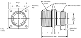
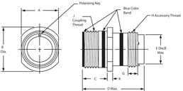
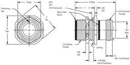
MS3450 J F A B C +.010 / -.005 F D Max. E K Shell Size Thread Class 2A Max./Min. +/-.031 Classes Classes KT, KS Max./Min. Size 16&12 Contacts Size 8,4,0 Contacts Dia. +/-.016 8S .5000-28 UNEF .593/.562 0.875 0.594 0.120(3.0) 0.150(3.8) .578/.562 1.662 - 0.5 0.083 10S .6250-24 UNEF .593/.562 1.000 0.719 0.120(3.0) 0.150(3.8) .578/.562 1.662 - 0.625 0.083 10SL .6250-24 UNEF .593/.562 1.000 0.719 0.120(3.0) 0.150(3.8) .578/.562 1.662 - 0.625 0.083 12 .7500-20 UNEF .781/.750 1.094 0.812 0.120(3.0) 0.150(3.8) .765/.750 1.662 - 0.750 0.083 12S .7500-20 UNEF .593/.562 1.094 0.812 0.120(3.0) 0.150(3.8) .578/.562 1.662 - 0.750 0.083 14 .8750-20 UNEF .781/.750 1.188 0.906 0.120(3.0) 0.150(3.8) .765/.750 1.662 - 0.875 0.083 14S .8750-20 UNEF .593/.562 1.188 0.906 0.120(3.0) 0.150(3.8) .578/.562 1.662 - 0.875 0.083 16 1.0000-20 UNEF .781/.750 1.281 0.969 0.120(3.0) 0.150(3.8) .765/.750 1.662 1.937 1.000 0.083 16S 1.0000-20 UNEF .593/.562 1.281 0.969 0.120(3.0) 0.150(3.8) .578/.562 1.662 - 1.000 0.083 18 1.1250-18 UNEF .781/.750 1.375 1.062 0.120(3.0) 0.177(4.5) .765/.750 1.662 1.937 1.062 0.125 20 1.2500-18 UNEF .781/.750 1.500 1.156 0.120(3.0) 0.177(4.5) .765/.750 1.662 1.937 1.187 0.125 22 1.3750-18 UNEF .781/.750 1.625 1.250 0.120(3.0) 0.177(4.5) .765/.750 1.662 1.937 1.312 0.125 24 1.5000-18 UNEF .843/.812 1.750 1.375 0.147(3.7) 0.177(4.5) .827/.812 1.662 1.937 1.437 0.125 28 1.7500-18 UNS .843/.812 2.000 1.562 0.147(3.7) 0.177(4.5) .827/.812 1.662 1.937 1.750 0.125 32 2.0000-18 UNS .906/.875 2.250 1.750 0.173(4.4) 0.209(5.3) .988/.875 1.662 1.937 2.000 0.125 36 2.2500-16 UN .906/.875 2.500 1.938 0.173(4.4) 0.209(5.3) .988/.875 1.662 1.937 2.250 0.125 40 2.5000-16 UN .906/.875 2.750 2.188 0.173(4.4) 0.209(5.3) .988/.875 1.662 1.937 2.500 0.125
MS3450, MS3451, MS3454 MS3451 MS3454 Shell Size D Max. D Max. H Thread Class 2A E Dia. Max. G Min. A Max./Min. B Dia. +/-.031 C Max./Min. A +/-.010 B +/-.005 C Dia. +/-.005 F +/-.005 8S 2.031 - .5000-20 UNEF 0.305 0.290 .504/.496 0.729 .577/.562 0.687 1.187 1.272 0.72 8S 2.031 - .5000-20 UNEF 0.305 0.290 .504/.496 0.729 .577/.562 0.687 1.187 1.272 0.720 10S 2.031 - .6250-24 UNEF 0.405 0.290 .629/.621 0.854 .577/.562 0.812 1.312 1.397 0.720 10SL 2.031 - .6250-24 UNEF 0.405 0.290 .629/.621 0.854 .577/.562 0.812 1.312 1.397 0.720 12 2.125 - .7500-20 UNEF 0.549 0.290 .754/.746 0.974 .765/.750 0.937 1.437 1.522 0.970 12S 2.031 - .7500-20 UNEF 0.549 0.290 .754/.746 0.974 .577/.562 0.937 1.437 1.522 0.720 14 2.125 - .8750-20 UNEF 0.665 0.290 .879/.871 1.099 .765/.750 1.125 1.562 1.647 0.970 14S 2.031 - .8750-20 UNEF 0.665 0.290 .879/.871 1.099 .577/.562 1.125 1.562 1.647 0.720 16 2.125 2.500 1.0000-20 UNEF 0.790 0.290 1.005/.996 1.224 .765/.750 1.250 1.687 1.772 0.970 16S 2.031 - 1.0000-20 UNEF 0.790 0.290 1.005/.996 1.224 .577/.562 1.250 1.687 1.772 0.720 18 2.125 2.500 1.0625-18 UNEF 0.869 0.290 1.131/1.121 1.349 .765/.750 1.375 1.812 1.897 0.970 20 2.125 2.500 1.1875-18 UNEF 0.994 0.290 1.256/1.246 1.474 .765/.750 1.500 1.937 2.022 0.970 22 2.125 2.500 1.3125-18 UNEF 1.119 0.290 1.381/1.371 1.599 .765/.750 1.625 2.156 2.241 0.970 24 2.125 2.500 1.4375-18 UNEF 1.244 0.290 1.506/1.496 1.715 .827/.812 1.750 2.281 2.366 0.970 28 2.125 2.500 1.7500-18 UNS 1.465 0.467 1.756/1.746 1.974 .827/.812 2.000 2.531 2.616 0.970 32 2.125 2.500 2.0000-18 UNS 1.715 0.467 2.007/1.996 2.224 .890/.870 2.375 2.781 2.866 0.970 36 2.125 2.500 2.2500-16 UN 1.930 0.467 2.257/2.246 2.474 .890/.870 2.625 3.031 3.116 0.970 40 2.125 2.500 2.2500-16 UN 2.145 0.467 2.511/2.456 2.724 .890/.870 2.875 3.281 3.366 0.970 ** Tolerance on this dimension is +.000/-.006 All dimensions in inches (millimeters in parentheses) PLUGSAMPHENOL MS3450 SERIES PLUGS
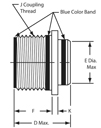
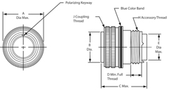
MS3456, MS3459 MS3456 MS3459 C Max. C Max. Shell Size B Dia. +/-.005 D Min. E Dia. Max. H Thread Class 2A J Thread Class 2A Size 16&12 Contacts Size 8,4,0 Contacts A Dia. Max. Size 16&12 Contacts Size 8,4,0 Contacts A Dia. Max. 8S 0.360 0.290 0.305 .5000-20 UNEF .5000-20 UNEF 2.031 - 0.844 1.510 - 0.963 10S 0.435 0.290 0.405 .6250-24 UNEF .6250-24 UNEF 2.031 - 0.969 1.510 - 1.088 10SL 0.441** 0.290 0.405 .6250-24 UNEF .6250-24 UNEF 2.031 - 0.969 1.510 - 1.088 12 0.550 0.290 0.549 .7500-20 UNEF .7500-20 UNEF 2.125 - 1.062 1.780 - 1.213 12S 0.550 0.290 0.549 .7500-20 UNEF .7500-20 UNEF 2.031 - 1.062 1.510 - 1.213 14 0.670 0.290 0.665 .8750-20 UNEF .8750-20 UNEF 2.125 - 1.156 1.780 - 1.358 14S 0.670 0.290 0.665 .8750-20 UNEF .8750-20 UNEF 2.031 - 1.156 1.510 - 1.358 16 0.800 0.290 0.790 1.0000-20 UNEF 1.0000-20 UNEF 2.125 2.500 1.250 1.780 2.500 1.463 16S 0.800 0.290 0.790 1.0000-20 UNEF 1.0000-20 UNEF 2.031 - 1.250 1.510 - 1.463 18 0.925 0.290 0.869 1.0625-18 UNEF 1.1250-18 UNEF 2.125 2.500 1.344 1.850 2.500 1.588 20 1.045 0.290 0.994 1.1875-18 UNEF 1.2500-18 UNEF 2.125 2.500 1.469 1.850 2.500 1.713 22 1.170 0.290 1.119 1.3125-18 UNEF 1.3750-18 UNEF 2.125 2.500 1.594 1.850 2.500 1.788 24 1.295 0.467 1.244 1.4375-18 UNEF 1.5000-18 UNEF 2.125 2.500 1.719 1.850 2.500 1.963 28 1.515 0.467 1.465 1.7500-18 UNS 1.7500-18 UNS 2.125 2.500 1.969 1.850 2.500 2.213 32 1.765 0.467 1.715 2.0000-18 UNS 2.0000-18 UNS 2.125 2.500 2.219 1.850 2.500 2.463 36 1.975 0.467 1.930 2.2500-16 UN 2.2500-16 UN 2.125 2.500 2.469 1.850 2.500 2.713 40 2.225 0.467 2.145 2.5000-16 UN 2.5000-16 UN 2.125 2.500 2.719 1.850 2.500 2.963 ** Tolerance on this dimension is +.000/-.006 All dimensions in inches PANEL CUTOUTSAMPHENOL MS3450 SERIES PANEL CUTOUTS
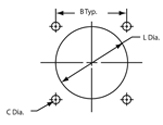
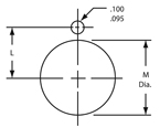
MS3450 (9440) MS3454/9444 MS3450/MS3452 MS3450 MS3454 Shell Size B L Dia. C Dia. Class K L Dia. M Dia. 8S 0.594 0.562 0.12 0.15 0.323 0.505 10S 0.719 0.688 0.120 0.150 0.385 0.630 10SL 0.719 0.688 0.120 0.150 0.385 0.630 12 0.812 0.812 0.120 0.150 0.448 0.755 12S 0.812 0.812 0.120 0.150 0.448 0.755 14 0.906 0.938 0.120 0.150 0.510 0.880 14S 0.906 0.938 0.120 0.150 0.510 0.880 16 0.969 1.062 0.120 0.150 0.573 1.005 16S 0.969 1.062 0.120 0.150 0.573 1.005 18 1.062 1.188 0.120 0.177 0.635 1.130 20 1.156 1.312 0.120 0.177 0.698 1.255 22 1.250 1.438 0.120 0.177 0.760 1.380 24 1.375 1.562 0.147 0.177 0.823 1.505 28 1.562 1.812 0.147 0.177 0.948 1.755 32 1.750 2.062 0.173 0.209 1.073 2.005 36 1.938 2.312 0.173 0.209 1.198 2.255 40 2.188 2.562 0.173 0.209 1.323 2.505 Click here, for gaskets. Click here, for nut plates and seal screws. All dimensions in inches DUMMY RECEPTACLES & METAL DUST CAPSAMPHENOL MS3450 SERIES DUMMY RECEPTACLES & METAL DUST CAPS
Dummy Receptacles Metal Dust Caps
Metal Dust Caps Shell Size Dummy Receptacles Plug Receptacle C Approx. D Dia. +.010/-.005 B Dia. +.010/-.005 8S MS3105-8 MS25042-8DA MS25043-8DA 4.000 0.156 0.140 10S, 10SL MS3105-10 MS25042-10DA MS25043-10DA 4.000 0.156 0.140 12, 12S MS3105-12 MS25042-12DA MS25043-12DA 4.500 0.156 0.140 14, 14S MS3105-14 MS25042-14DA MS25043-14DA 4.500 0.156 0.140 16S MS3105-16 MS25042-16DA MS25043-16DA 4.500 0.156 0.140 16 MS3105-17 MS25042-16DA MS25043-16DA 4.500 0.156 0.140 18 MS3105-18 MS25042-18DA MS25043-18DA 4.500 0.156 0.140 20 MS3105-20 MS25042-20DA MS25043-20DA 5.000 0.187 0.140 22 MS3105-22 MS25042-22DA MS25043-22DA 5.000 0.187 0.140 24 MS3105-24 MS25042-24DA MS25043-24DA 5.500 0.187 0.171 28 MS3105-28 MS25042-28DA MS25043-28DA 7.750 0.187 0.171 32 MS3105-32 MS25042-32DA MS25043-32DA 7.750 0.218 0.187 36 MS3105-36 MS25042-36DA MS25043-36DA 7.750 0.218 0.187 40 MS3105-40 MS25042-40DA MS25043-40DA 7.750 0.218 0.187 Note: Stainless steel dust caps and other lanyards available, please contact us. Aluminum alloy with anodized plating is shown. Contact us for other available dust cap materials and platings. All dimensions in inches |
|
AMPHENOL MS3450 SERIES STANDARD CABLE CLAMPS
Straight Clamp 90° Cable Entry Shell Size Low-Cost Self-Locking Low-Cost Self-Locking Max. Min. 8 M85049/52-1-8* M85049/52S8* M85049/51-1-8* M85049/51S8* .204 (5.18) .125 (3.18) 10S, 10SL M85049/52-1-10* M85049/52S10* M85049/51-1-10* M85049/51S10* .286 (7.26) .187 (4.75) 12, 12S M85049/52-1-12* M85049/52S12* M85049/51-1-12* M85049/51S12* .416 (10.57) .291 (7.39) 14, 14S M85049/52-1-14* M85049/52S14* M85049/51-1-14* M85049/51S14* .476 (12.09) .351 (8.92) 16, 16S M85049/52-1-16* M85049/52S16* M85049/51-1-16* M85049/51S16* .626 (15.88) .501 (12.72) 18 M85049/52-1-18* M85049/52S18* M85049/51-1-18* M85049/51S18* .706 (17.93) .518 (13.16) 20 M85049/52-1-20* M85049/52S20* M85049/51-1-20* M85049/51S20* .831 (21.11) .581 (14.76) 22 M85049/52-1-22* M85049/52S22* M85049/51-1-22* M85049/51S22* .956 (24.28) .644 (16.36) 24 M85049/52-1-24* M85049/52S24* M85049/51-1-24* M85049/51S24* 1.081 (27.46) .706 (17.93) 28 M85049/52-1-28* M85049/52S28* M85049/51-1-28* M85049/51S28* 1.187 (30.15) .750 (19.05) 32 M85049/52-1-32* M85049/52S32* M85049/51-1-32* M85049/51S32* 1.250 (31.75) .875 (22.23) 36 M85049/52-1-36* M85049/52S36* M85049/51-1-36* M85049/51S36* 1.375 (34.93) .938 (23.83) 40 M85049/52-1-40* M85049/52S40* M85049/51-1-40* M85049/51S40* 1.500 (38.10) .938 (23.83) * = Select plating code to match connector plating. N = Electroless Nickel-Plated Aluminum Alloy W = Olive Drab Chromate over Cadmium over Electroless Nickel-Plated Aluminum Alloy S = Stainless Steel
Part Number
Heat Shrink Boot Adapter M85049/60 X
Environmental M85049/7 M85049/9 M85049/11 X X X
EMI/RFI Non-Environmental M85049/23 M85049/24 M85049/25 X X X
EMI/RFI Environmental M85049/6 M85049/8 M85049/10 X X X
EMI/RFI Crimp Ring M85049/26 X
EMI/RFI Banding M85049/82 M85049/83 M85049/84 X X X
Cable Tie M85049/55 M85049/53 M85049/54 X X X
Wire Seal Compression Nuts “E” M85049/31 X Note: If military standard versions won’t fit your applications, please contact us with your requirements. |
|
WIRE-STRIPPING AND CONTACT-CRIMPINGAMPHENOL MS3450 SERIES WIRE-STRIPPING AND CONTACT-CRIMPING
.245 (6.2) for #16/16S Contact .465 (11.8) for #8 Contact .540 (13.7) for #0 Contact 
.245 (6.2) for #12 Contact .465 (11.8) for #4 Contact
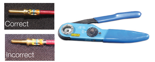
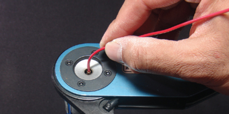
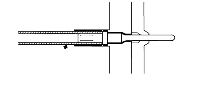
STEP 1: Strip wires. (See above for correct strip length by contact.) Insert wire into rear of contact. Wire insulation must push against rear of contact. Wire must be visible through inspection hole. STEP 2: Use M22520/1-01 crimp tool with proper crimp locator M22520/1-02. Click here for additional tooling. Contact Size Color 16/16S Blue 12 Yellow STEP 3: Insert contact and wire into tool jaws. To crimp, squeeze handles together fully until ratchet releases and allows handles to expand, otherwise contact cannot be extracted from tool jaws. Maintain slight insertion pressure on wire while crimping contact to wire.* CONTACT INSERTIONAMPHENOL MS3450 SERIES CONTACT INSERTION
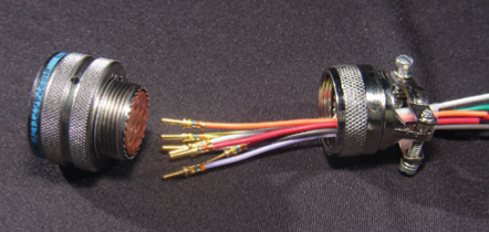
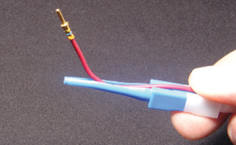
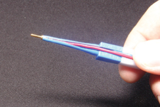
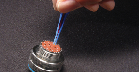
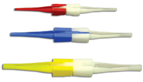
STEP 1: Remove backshell and put wired contacts through cable clamp opening. STEP 2: Use colored end of CIET tool for insertion. Place wire into tool at large opening. To facilitate contact insertion, a six-inch minimum of free wire is recommended. STEP 3: Slide back tool on wire while holding thumb against wire at opening. Wire will slip into tool.
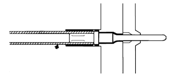
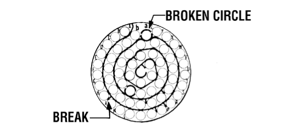
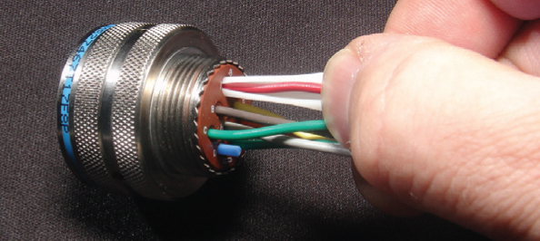
STEP 4: With tool pressed against shoulder of contact, starting at the center cavity, insert wired contact and tool into properly-identified cavity at rear of plug with firm, even pressure. Do not use excessive pressure. STEP 5: When contact touches bottom, a slight click can be heard as tines of metal retaining clip snap into place behind contact shoulder. STEP 6: Check face of plug or receptacle for proper contact installation. In socket inserts with a large number of contacts, cavities are identified in a spiral pattern. A projecting line from the spiral indicates omission of a letter; a broken circle around a cavity indicates transition between capitals, and lower case and double letters. STEP 7: Withdraw tool from rear of plug. To be sure that contact is locked, pull back lightly on wire. Remove tool from wire and proceed with other contacts. STEP 8: After all contacts are inserted, fill unwired cavities with sealing plugs (insert head first and leave end protruding for ease of removal), assemble backshell on rear of connector. * IMPORTANT NOTE: Microsection the contact to verify crimp quality. CONTACT EXTRACTIONAMPHENOL MS3450 SERIES CONTACT EXTRACTION
STEP 1: Remove backshell and slide back along wires to allow access. To extract a contact, use white end of CIET tool. Place wire into tool at large opening. Slide back tool on wire while holding thumb against wire at opening. Wire will slip into tool. STEP 2: Push tool into rear of plug until it touches bottom. At this point, tool releases tines on retaining clip so that contact can be extracted. STEP 3: While maintaining slight insertion force on tool, firmly hold wire against serrated shoulder at center of tool and extract both wired contact and tool from plug.
|
Philadelphia
19116
Click here for the contact information of the branch nearest you.










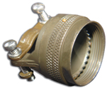
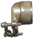 Light-weight, open-rear design


