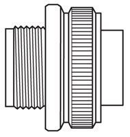
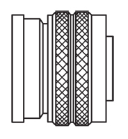
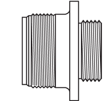
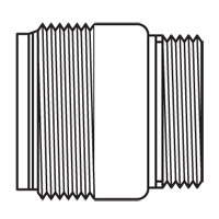
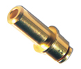
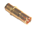
Amphenol AIT / MS Connectors (SAE-AS50151)
ENVIRONMENTALLY-SEALED FOR CHALLENGING ENVIRONMENTS
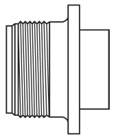
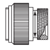
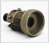
Amphenol AIT / MS connectors are cost-effective threaded circular SAE-AS50151 (MIL-DTL-5015) connectors for use in harsh environments. These Amphenol MS connectors are sealed to withstand moisture, condensation, vibration and flash-over. Over 286 contact layouts are available, in variations that allow for just power, just signal, or a mix of both contact types. Amphenol AIT / MS connectors are available in five mounting styles, nineteen shell sizes, and solder or crimp termination.
Get shopping! Part numbers begin with AIT.
|
FEATURESAMPHENOL AIT/MS SERIES FEATURES
MATERIALS & FINISHESAMPHENOL AIT/MS SERIES MATERIALS & FINISHES
Shell Aluminum alloy
Shell Plating Olive drab chromate coating over cadmium plating to QQ-P-416; black alloy, electroless nickel, anodized, gray zinc nickel or green zinc
Contacts Brass or copper alloy
Contact Plating Silver plating to ASTM B700 (solder contacts have tinned solder pot) gold plating to ASTM B488
Insulator Resilient Neoprene®, Viton®*, low-smoke, zero-halogen (LSZH)
ELECTRICAL DATAAMPHENOL AIT/MS SERIES ELECTRICAL DATA
Operating Voltage/Test Voltage
Standard Sea Level Conditions Pressure Altitude 50,000† Feet Pressure Altitude 70,000† Feet MS Service Rating Airspace Creepage DC V AC VRMS Minimum Flashover Voltage AC (RMS) Test Voltage AC (RMS) Minimum Flashover Voltage AC (RMS) Test Voltage AC (RMS) Minimum Flashover Voltage AC (RMS) Test Voltage AC (RMS) I 1/32 1/16 250 200 1,400 1,000 550 400 325 260 A 1/16 1/8 700 500 2,800 2,000 800 600 450 360 D 1/8 3/16 1,250 900 3,600 2,800 900 675 500 400 E 3/16 1/4 1,750 1,250 4,500 3,500 1,000 750 550 440 B 1/4 5/16 2,450 1,750 5,700 4,500 1,100 825 600 480 C 5/16 1 4,200 3,000 8,500 7,000 1,300 975 700 560 * Each insulator has a specific service rating. These should be used by the designer only as a guide. † Not corrected for change in density resulting from variations in temperature MS connectors show no evidence of breakdown when the given test voltages are applied between the two closest contacts and between the shell and the contacts closest to the shell for a period of one minute, per MIL-STD-1344 Method 3001. Current Rating & Contact Resistance
Contact Resistance 16 13 49 6 12 23 (50*) 42 3 8 46 (69*) 26 (20*) 1 (0.44*) 4 80 (80*) 23 (18*) 0.5 (0.23*) 0 150 (225*) 21 (27*) 0.2 (0.18*) * Using non-military crimp Radsok contact Maximum total current to be carried per connector in wire bundles as specified in MIL-W-5088. Contact resistance when tested to MIL-C-39029 will not exceed voltage drops listed in above table. Viton® is a registered trademark of Dupont Dow Elastomers MECHANICALAMPHENOL AIT/MS SERIES MECHANICAL
Wire Range Sizes 26 to 0 AWG (crimp contacts)
Insulation Resistance 5000 megohms at 77°F (25°C) per SAE-AS50151 (MIL-DTL-5015), 3.18
Wire Sealing Range Insulation Outside Diameter Limit Contact Size Wire Size Min. Min. Max. Max. 16 16 thru 20 .064 1.63 .130 3.30 12 12 thru 14 .114 2.90 .170 4.32 8 8 thru 10 .164 4.17 .255 6.48 4 4 thru 6 .275 6.98 .370 9.40 0 0 thru 2 .415 10.54 .550 13.97 The connector is designed for individual wire sealing. Sealing of an outer cable jacket on multiconductor cables must be accomplished with an appropriate endbell. Sealing is only guaranteed if wires according to MIL-W-5086 or within the listed ranges are used. Insulation Strip Lengths
Mating Life 100 cycles minimum, to SAE-AS50151 (MIL-DTL-5015), 3.16
Salt Spray MIL-STD-1344 Method 1001 condition B minimum (cadmium), 48-hour, olive drab chromate over cadmium, non-conductive black alloy, conductive black alloy, green zinc, black anodized, electroless nickel, Gray Zinc Nickel 500 hours salt spray
Heat +257˚F (+125˚C) for 60 hours, +185˚F (+85˚C) for 1,000 hours per
SAE-AS50151 (MIL-DTL-5015), 4.6.14, minimum
Chemical Resistance 20-hour full-immersion unmated in hydraulic fluid and lubricating oil
per SAE-AS50151 (MIL-DTL-5015) minimum
Vibration 10 to 2,000Hz (10g's) 10 microseconds maximum discontinuity
to MIL-STD-1344 Method 2005, condition II per SAE-AS50151 (MIL-DTL-5015)
Shock 50g 11-millisecond duration, three major axes. 10 microseconds maximum discontinuity to SAE-AS50151 (MIL-DTL-5015)
per MIL-STD-1344 method 2004, condition A, 3.13
Contact Type Solder, crimp, PC, thermocouple (hard silver or gold plating) or first-mate last-break
Number of Circuits
Contact Insertion Insertion from rear with simple hand tool. Removable, five cycles
minimum. (Solder, PC and co-ax outer housings are bonded into
the insulator.)
Contact Retention To SAE-AS50151 (MIL-DTL-5015), 4.6.6 & 3.26 and separation forces
Axial Load Separation Force Minimum Contact Size Newtons Lbs. Newtons Lbs. 16 44 10 1 0.25 12 67 15 2 0.50 8 89 20 3 0.75 4 89 20 4 1.00 0 111 25 9 2.00 Polarization Integral key and keyway plus optional rotational polarization. Click here for valid rotations.
Approvals SAE-AS50151 (MIL-DTL-5015)
|
|
AMPHENOL AIT/MS SERIES APPLICATIONS
Military, industrial and commercial environments requiring extreme reliability, high-power handling and cost efficiency.
|
|
STEP 1: SHELLAMPHENOL AIT/MS SERIES EXAMPLE
STEP 1 2 3 4 5 6 7 8 AIT 6 A A 24-21 S S -472 SERIES PREFIX SHELL STYLE ENDBELLS CABLE CLAMP/
BOOT LAYOUT CONTACT ROTATION CONTACT TYPE PLATING STEP 1: SELECT SHELL STYLE, PLUG OR RECEPTACLE
6
6B
0
1 Cable Mount with Accessory Threads (MS3101)
2 Box Mount No Accessory Threads (MS3102) STEP 2: ENDBELLSTEP 2: SELECT ENDBELL
TIP: Order connector, backshell and all accessories as one part number! See www.peigenesis.comindex.php?format=html&Itemid=903&option=com_content&view=category&layout=blog&id=161
F Sealed
STEP 3: CABLE CLAMPSTEP 3: SELECT CABLE CLAMP OR BOOT (if applicable)
STEP 7: CONTACTSTEP 7: SELECT CONTACT TYPE

S = Solder C = Crimp * When using "C" in part number, the connector is supplied with the standard size crimp contacts for its layout. Bolded part numbers indicate crimp contact. Please contact us for connectors with reduced or enlarged crimp barrel contacts. ** Click here for post diameters and lengths. STEP 8: PLATINGSTEP 8: SELECT PLATING


CONTACTS SHELL PLATING MATERIALS B30 = Gold 50μ Gold over Nickel 023 = Electroless Nickel L = Low-smoke, zero-halogen T = Thermocouple (solder only) 024 = Green Zinc Cobalt V = High-temperature Viton® RDS = RADSOK (crimp socket only) 025 = Black Alloy 116 = Less pre-tinned solder cups 027 = Conductive Black Alloy G96 = Black Anodized 072 = Gray Zinc Nickel (RoHS with crimp or 116 contacts) 472 = 116&025 mod codes (RoHS) 548 = 116&023 mod codes (RoHS) 553 = 116&027 mod codes (RoHS) 724 = 116&072 mod codes (RoHS) Standard Specials -- contact us with NPT thread size, seal title conduit diameter, or cable outside diameter. Internal Thread Version Low Cost Gland Seal Conduit Metal Shielded Cable Conduit Plastic Gland Seal Mesh Grip Need Help? PEI engineers will help you solve your design challenges and build the perfect part for your application. Email us at [email protected] or complete our online Technical Request at www.peigenesis.com/technical-support. To contact us by phone, please click here for a complete listing of our branch offices and numbers. |
|
PIN & SOCKET CRIMP CONTACTSAMPHENOL AIT/MS SERIES PIN & SOCKET CRIMP CONTACTS
Pin Contact Socket Contact Wire Strip Length Wire Range
Part Number Part Number Wire Strip Wire Sealing Contact Size Wire Size AWG Silver Gold Silver Gold Inches Inches (MM)
16-18-20 12-14 14-16 18-20 20-22 22-24 AIC16S-16P* AIC16S-12P AIC16S-14P AIC16S-20P AIC16S-22P AIC16S-24P AIC16S- AIC16S- AIC16S- AIC16S- AIC16S- AIC16S- AIC16S-16S* AIC16S-12S AIC16S-14S AIC16S-20S AIC16S-22S AIC16S-24S AIC16S- AIC16S- AIC16S- AIC16S- AIC16S- AIC16S- C4 C3 C13 C14 C2 0.312 (7.9) .090-.118 (2.3-3.0) 16 16-18-20 12-14 14-16 18-20 20-22 20-24 22-24 AIC16-16P* AIC16-12P AIC16-14P AIC16-18P AIC16-20P AIC16-2024P AIC16-22P AIC16-16PG* AIC16-12PG AIC16-14PG AIC16-18PG AIC16-20PG AIC16- AIC16-22PG AIC16-16S* AIC16-12S AIC16-14S AIC16-18S AIC16-20S AIC16-2024S AIC16-22S AIC16-16SG* AIC16-12SG AIC16-14SG AIC16-18SG AIC16-20SG AIC16- AIC16-22SG C4 C3 C13 C14 C36 C2 0.312 (7.9) .090-.118 (2.3-3.0)
12-14 12 High-Power 8-10 10-12 14-16 16-18 18-20 20-22 AIC12-12P* - AIC12-8P AIC12-10P AIC12-14P AIC12-16P AIC12-18P AIC12-20P AIC12-12PG* - AIC12-8PG AIC12-10PG AIC12-14PG AIC12-16PG AIC12-18PG AIC12-20PG AIC12-12S* AIC12- AIC12-8S AIC12-10S AIC12-14S AIC12-16S AIC12-18S AIC12-20S AIC12-12SG* - AIC12-8SG AIC12-10SG AIC12-14SG AIC12-16SG AIC12-18SG AIC12-20SG C5 C8 C9 C7 C6 C40 0.312 (7.9) .126-.177 (3.2-4.5)
8 8 High-Power 10-12 12-14 AIC8-8P* - AIC8-10P AIC8-12P AIC8-8PG* - AIC8-10PG AIC8-12PG AIC8-8S* AIC8-8SRAD AIC8-10S AIC8-12S AIC8-8SG* - AIC8-10SG AIC8-12SG C10 C38 0.563 (14.3) .150-.256 (3.8-6.5) 4 4 4 High-Power 8 AIC4-4P* - AIC4-8P AIC4-4PG* - AIC4-8PG AIC4-4S* AIC4-4SRAD AIC4-8S AIC4-4SG* - AIC4-8SG C15 0.500 (12.7) .279-.366 (7.1-9.3) 0 0 0 High-Power 0-2 4 AIC0-0P* - AIC0-2P AIC0-4P AIC0-0PG* - AIC0-2PG AIC0-4PG AIC0-0S* AIC0-0SRAD AIC0-2S AIC0-4S AIC0-0SG* - AIC0-2SG AIC0-4SG C11 C12 0.750 (19.0) .394-.539 (10.0-13.7) *Bolded items are standard crimp contacts. Solder Thermocouple Contacts Contact Size Type Pins Sockets 16S† Alumel Chromel Iron Constantan 10-040799-02P* 10-040799-01P* 10-040799-03P* 10-040799-04P* 10-040799-02S* 10-040799-01S* 10-040799-03S* 10-040799-04S* 16 Alumel Chromel Iron Constantan 10-040799-12P* 10-040799-11P* 10-040799-13P* 10-040799-14P* 10-040799-12S* 10-040799-11S* 10-040799-13S* 10-040799-14S* 12 Alumel Chromel Iron Constantan 10-040799-42P* 10-040799-41P* 10-040799-43P* 10-040799-44P* 10-040799-42S* 10-040799-41S* 10-040799-43S* 10-040799-44S* Thermocouple Types: J = Iron-Constantan K = Alumel-Chromel T = Copper-Constantan E = Chromel-Constantan *Contact us for availability. † 16S contacts are used in 8S, 10S, 10SL, 12S, 14S & 16S connector sizes only. CRIMP TOOLSAMPHENOL AIT/MS SERIES CRIMP TOOLS
Accessories Tools
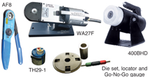
Contact Size Wire Hole Crimp Tools Crimp Locator & Die Sets Locator Color Pilot Pin/Insertion Guide for Sockets Insertion Tool Extraction Tool 16S† Blue AF8-(hand) WA27F-(pneumatic) †† TH29-1 Red 10-242758-016 DAK168-16 DRK59 Kit with Multiple Tips 16 Blue AF8-(hand) WA27F-(pneumatic) †† TH29-1 Pin-BlueSocket-Green 10-242758-016 DAK168-16 DRK59 Kit with Multiple Tips 12 Yellow AF8-(hand) WA27F-(pneumatic) †† TH29-1 Green 10-242758-012 DAK168-12 DRK59 Kit with Multiple Tips 8 Red 400BHD Die Set - 10-242758-008 AIC8INS DRK59 Kit with Multiple Tips 4 Blue 400BHD Die Set - - AIC4INS AIC4EXT-P (Pin) 0 Yellow 400BHD Die Set - - AIC0INS AIC0EXT-P (Pin) †† Contact us for additional tool accessories. PIN & SOCKET CO-AX CONTACTSAMPHENOL AIT/MS SERIES PIN & SOCKET CO-AX CONTACTS
Pin Contact Socket Contact Wire Strip Length Wire Range Accessories
Part Number Part Number Wire Sealing Range Inches (MM) Co-ax Contact Co-ax Wire Size Silver Gold Silver Gold Wire Strip Lengths Inches (MM) Min. Max. Wire Hole Filler 12 RG161/U RG174A/U RG179B/U RG187A/U RG188A/U RG316/U RG178B/U RG196A/U 21-33034-1 - 21-33014-21 21-33048-1( ) 21-33130-1( ) 21-33014-22 21-33033-1 - 21-33013-21 21-33047-1( ) 21-33129-1( ) 21-33013-22 0.126 0.177 Yellow 8 RG58C/U RG141A/U RG303/U RG59B/U RG62A/U RG62B/U RG210/U RG161/U RG174A/U RG179B/U RG187A/U RG188A/U RG316/U RG180B/U RG195A/U RG140/U RG302/U RG55B/U RG142A/U RG142B/U RG223/U 21-33034-2(1) 21-33034-5(1) 21-33034-3(1) 21-33034-6 21-33034-8 21-33034-4 21-33014-1(5) 21-33016-5(3) 21-33130-2( ) 21-33014-5(5) 21-33016-2(3) 21-33130-5( ) 21-33064- 21-33014-3(5) 21-33016-1(3) 21-33130-3( ) 21-33064- 21-33014-6(5) 21-33048-3( ) 21-33130-6( ) 21-33014-8(5) 21-33033-8 21-33130-8( ) 21-33014-5(5) 21-33130-4( ) 21-33033-2(1) 21-33048-2( ) 21-33033-3(1) 21-33033-3(1) 21-33033-6 - 21-33033-4 21-33013-1(5) 21-33047-2() 21-33015-5(3) 21-33129-2( ) 21-33013-5(5) 21-33015-2(3) 21-33129-3( ) 21-33063- 21-33013-3(5) 21-33015-1(3) 21-33129-3( ) 21-33063- 21-33013-(6) 21-33047-3( ) 21-33129-6( ) 21-33013-8(5) 21-33129-8( ) 21-33013-5(5) 21-33129-4( ) 0.150 0.256 White 4 RG59B/U RG62A/U RG62B/U RG210/U RG212/U RG55B/U RG142A/U RG142B/U RG223/U - 21-33060- 21-33060- 31-33060- - 21-33059- 21-33059- 21-33059- 0.279 0.366 Blue ( ) Various platings available. Availability of co-ax contacts varies widely. Contact us for details. All dimensions in inches (millimeters in parentheses) CO-AX TOOLSAMPHENOL AIT/MS SERIES CO-AX TOOLS
Tools
Co-ax Contact Size Co-ax Wire Size Hand Crimp Tool Hand Crimp Tool Use Locator Co-ax Clamp Nut Wrench 12 RG161/U RG174A/U RG179B/U RG187A/U RG188A/U RG316/U RG178B/U RG196A/U M22520/10-01 M22520/10-05 A B 11-8676-1 8 RG58C/U RG141A/U RG303/U RG59B/U RG62A/U RG62B/U RG210/U RG161/U RG174A/U RG179B/U RG187A/U RG188A/U RG316/U RG180B/U RG195A/U RG140/U RG302/U RG55B/U RG142A/U RG142B/U RG223/U M22520/10-01 M22520/5-01 M22520/10-01 M22520/10-07 M22520/5-45 M22520/10-05 M22520/10-07 B B A B A 11-8676-2 11-8676-3 11-8676-2 4 RG59B/U RG62A/U RG62B/U RG210/U RG212/U RG55B/U RG142A/U RG142B/U RG223/U M22520/5-01 M22520/5-01 M22520/10-01 M22520/5-45 M22520/5-34 M22520/10-07 B A A - 11-8676-4 - All dimensions in inches (millimeters in parentheses) |
|
RECEPTACLESAMPHENOL AIT/MS SERIES RECEPTACLES
AIT0/
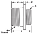
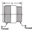
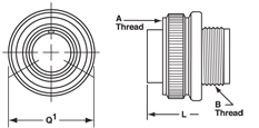
Shell Size A Thread Class 2A M +.010 -.000 P Ref. R +/-.005 S +/-.031 T Dia. +.004 -.002 L Ref. Length KK Dia. +.010 -.000 Length 3100 3101 Q Dia. B Thread Class 2A 8S .5000-28UNEF 0.562 (14.3) 0.110 (2.8) 0.594 (15.1) 0.875 (22.2) 0.120 (3.0) 0.969 (24.6) 0.375 (9.5) 1.087 (27.6) 0.532 (13.5) .5000-28UNEF 10S .6250-24NEF 0.562 (14.3) 0.110 (2.8) 0.719 (18.3) 1.000 (25.4) 0.120 (3.0) 0.969 (24.6) 0.500 (12.7) 1.087 (27.6) 0.628 (16.0) .5000-28UNEF 10SL .6250-24NEF 0.562 (14.3) 0.110 (2.8) 0.719 (18.3) 1.000 (25.4) 0.120 (3.0) 0.969 (24.6) 0.625 (15.9) 1.087 (27.6) 0.755 (19.2) .6250-24UNEF 12S .7500-20UNEF 0.562 (14.3) 0.110 (2.8) 0.812 (20.6) 1.094 (27.8) 0.120 (3.0) 0.969 (24.6) 0.625 (15.9) 1.087 (27.6) 0.755 (19.2) .6250-24UNEF 12 .7500-20UNEF 0.750 (19.1) 0.110 (2.8) 0.812 (20.6) 1.094 (27.8) 0.120 (3.0) 1.344 (34.1) 0.625 (15.9) 1.334 (33.9) 0.755 (19.2) .6250-24UNEF 14S
0.562 (14.3) 0.110 (2.8) 0.906 (23.0) 1.188 (30.2) 0.120 (3.0) 0.969 (24.6) 0.750 (19.1) 1.087 (27.6) 0.882 (22.4) .7500-20UNEF 14 .8750-20UNEF 0.750 (19.1) 0.110 (2.8) 0.906 (23.0) 1.188 (30.2) 0.120 (3.0) 1.344 (34.1) 0.750 (19.1) 1.334 (33.9) 0.882 (22.4) .7500-20UNEF 16S 1.0000-20UNEF 0.562 (14.3) 0.110 (2.8) 0.969 (24.6) 1.281 (32.5) 0.120 (3.0) 0.969 (24.6) 0.875 (22.2) 1.087 (27.6) 1.010 (25.7) .8750-20UNEF 16 1.0000-20UNEF 0.750 (19.1) 0.110 (2.8) 0.969 (24.6) 1.281 (32.5) 0.120 (3.0) 1.344 (34.1) 0.875 (22.2) 1.334 (33.9) 1.010 (25.7) .8750-20UNEF 18 1.1250-18NEF 0.750 (19.1) 0.141 (3.6) 1.062 (27.0) 1.375 (34.9) 0.120 (3.0) 1.344 (34.1) 1.000 (25.4) 1.334 (33.9) 1.137 (28.9) 1.0000-20UNEF 20 1.2500-18NEF 0.750 (19.1) 0.141 (3.6) 1.156 (29.4) 1.500 (38.1) 0.120 (3.0) 1.344 (34.1) 1.125 (28.6) 1.334 (33.9) 1.264 (32.1) 1.1250-18UNEF 22 1.3750-18NEF 0.750 (19.1) 0.141 (3.6) 1.250 (31.8) 1.625 (41.3) 0.120 (3.0) 1.344 (34.1) 1.250 (31.8) 1.334 (33.9) 1.392 (35.4) 1.2500-18UNEF 24 1.5000-18NEF 0.812 (20.6) 0.141 (3.6) 1.375 (34.9) 1.750 (44.5) 0.147 (3.7) 1.406 (35.7) 1.375 (34.9) 1.406 (35.7) 1.519 (38.6) 1.3750-18UNEF 28 1.7500-18NS 0.812 (20.6) 0.141 (3.6) 1.562 (39.7) 2.000 (50.8) 0.147 (3.7) 1.406 (35.7) 1.625 (41.3) 1.406 (35.7) 1.774 (45.1) 1.6250-18UNEF 32 2.0000-18NS 0.875 (22.2) 0.156 (4.0) 1.750 (44.5) 2.250 (57.2) 0.173 (4.4) 1.469 (37.3) 1.875 (47.6) 1.469 (37.3) 1.996 (50.7) 1.8750-16UN 36 2.2500-16UN 0.875 (22.2) 0.156 (4.0) 1.938 (49.2) 2.500 (63.5) 0.173 (4.4) 1.469 (37.3) 2.062 (52.4) 1.469 (37.3) 2.251 (57.2) 2.0625-16UN 40 2.5000-16UN 0.875 (22.2) 0.156 (4.0) 2.188 (55.6) 2.750 (69.9) 0.173 (4.4) 1.469 (37.3) 2.312 (58.7) 1.469 (37.3) 2.506 (63.7) 2.3125-16UN All dimensions in inches (millimeters in parentheses) ENDBELL STYLESAMPHENOL AIT/MS SERIES ENDBELL STYLES
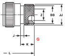
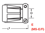
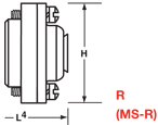
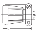
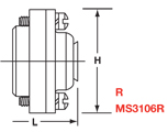
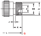
AIT0-MS3100/AIT1-MS3101 AIT0/AIT1 G A & L Endbell E Endbell R Endbell Shell Size L1 L2 Max. B Thread Class 2A L XX Cable Min. L H Dia. Max. L Max. J ± .008 (±0.2) K ± .020 (+0.5) Z Min. BB Max. JJ +.008 (+.02) 8S 1.39 (35.3) 3.2 (81.20) .5000-28 UNEF - - 1.588 (40.3) 0.959 (24.4) - - - - - - 10S 1.468 (37.3) 3.2 (81.20) .5000-28 UNEF - - 1.588 (40.3) 1.026 (26.1) - - - - - - 10SL 1.468 (37.3) 3.23 (93.6) .6250-24 NEF 2.129 (54.1) 0.281 (7.1) 1.588 (40.3) 1.120 (28.4) 1.969 (50.0) 0.138 (3.5) 0.461 (11.7) 0.303 (7.7) 0.524 (13.3) 0.610 (15.5) 12S 1.468 (37.3) 3.58 .6250-24 NEF 2.129 (54.1) 0.281 (7.1) 1.588 (40.3) 1.120 (28.4) - - - - - - 12 1.843 (46.8) 3.66 .6250-24 NEF 2.129 (54.1) 0.281 (7.1) 1.931 (49.0) 1.120 (28.4) - - - - - - 14S 1.468 (37.3) 3.23 (82.09) .7500-20 UNEF 2.201 (55.9) 0.406 (10.3) 1.588 (40.3) 1.307 (33.2) 1.969 (50.0) 0.138 (3.5) 0.461 (11.7) 0.417 (10.6) 0.669 (17.0) 0.752 (19.1) 14 1.843 (46.8) 3.64 .7500-20 UNEF 2.524 (62.1) 0.406 (10.3) 1.931 (49.0) 1.307 (33.2) - - - - - - 16S 1.468 (37.3) 3.23 (82.09) .8750-20 UNEF 2.201 (55.9) 0.500 (12.7) 1.588 (40.3) 1.432 (36.4) 1.969 (50.0) 0.138 (3.5) 0.461 (11.7) 0.531 (13.5) 0.862 (21.9) 0.941 (23.9) 16 1.843 (46.8) 3.58 (91.03) .8750-20 UNEF 2.524 (62.1) 0.500 (12.7) 1.931 (49.0) 1.432 (36.4) 2.362 (60.0) 0.138 (3.5) 0.453 (11.5) 0.531 (13.5) 0.862 (21.9) 0.941 (23.9) 18 1.938 (49.2) 3.66 (92.94) 1.000-20 UNEF 2.596 (65.9) 0.531 (13.5) 1.931 (49.0) 1.557 (39.5) 2.362 (60.0) 0.138 (3.5) 0.453 (11.5) 0.575 (14.5) 0.862 (21.9) 0.941 (23.9) 20 1.844 (46.8) 3.64 (92.56) 1.1875-18 NEF 2.654 (67.4) 0.656 (16.7) 1.931 (49.0) 1.744 (44.3) 2.559 (65.0) 0.138 (3.5) 0.500 (12.7) 0.736 (18.7) 1.031 (26.2) 1.165 (29.6) 22 1.938 (49.2) 3.65 (92.68) 1.1875-18 NEF 2.654 (67.4) 0.740 (18.8) 1.931 (49.0) 1.869 (47.5) 2.559 (65.0) 0.138 (3.5) 0.500 (12.7) 0.819 (20.8) 1.031 (26.2) 1.165 (29.6) 24 1.969 (50.0) 3.73 (94.64) 1.4375-18 NEF 2.885 (73.3) 0.781 (19.8) 2.009 (51.0) 1.994 (50.6) 2.559 (65.0) 0.138 (3.5) 0.500 (12.7) 0.969 (24.6) 1.358 (34.5) 1.488 (37.8) 28 2.188 (55.6) 3.90 (98.96) 1.4375-18 NEF 2.885 (73.3) 0.922 (23.4) 2.009 (51.0) 2.166 (55.0) 2.559 (65.0) 0.138 (3.5) 0.500 (12.7) 1.063 (27.0) 1.358 (34.5) 1.488 (37.8) 32 2.157 (54.8) 4.10 (104.24) 1.7500-18 NS 2.943 (74.8) 1.156 (29.4) 2.072 (52.6) 2.541 (64.5) 2.756 (70.0) 0.138 (3.5) 0.598 (15.2) 1.311 (33.3) 1.717 (43.6) 1.882 (47.8) 36 2.219 (56.4) 4.15 (105.38) 2.0000-18 NS 2.943 (74.8) 1.250 (31.8) 2.072 (52.6) 2.729 (69.3) 3.150 (80.0) 0.138 (3.5) 0.598 (15.2) 1.516 (38.5) 1.717 (43.6) 1.882 (47.8) 40 2.188 (55.6) 4.15 (105.38) 2.2500-16 UN 3.068 (77.9) 1.562 (39.7) 2.072 (52.6) 2.979 (75.7) 3.150 (80.0) 0.138 (3.5) 0.610 (15.5) 1.898 (48.2) 2.070 (52.6) 2.276 (57.8) All dimensions in inches (millimeters in parentheses) STYLE 6AMPHENOL AIT/MS SERIES STYLE 6 PLUGS, ENDBELLS & RIGHT ANGLE ENDBELLS
STYLE 6 PLUGS STYLE 6 ENDBELLS
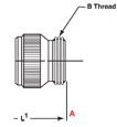
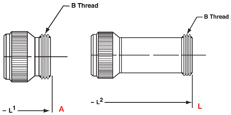
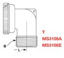
MS3106E A & L MS3106E/MS3106F Shell Size A Thread Class 2B Q1 Dia. Max. Barrel B L1 L2 B Thread Class 2A L Max. Cable Min. XX 8S .5000-28 UNEF 0.741 (18.8) .5000-28 UNEF 1.390 (35.3) - .5000-28 UNEF - - 8S .5000-28 UNEF 0.741 (18.8) .5000-28 UNEF 1.390 (35.3) - .5000-28 UNEF - - 10S .6250-24 NEF 0.869 (22.1) .5000-28 UNEF 1.468 (37.3) - .5000-28 UNEF - - 10SL .6250-24 NEF 0.946 (24.0) .6250-24 UNEF 1.468 (37.3) 3.684 (93.6) .6250-24 NEF 2.129 (54.1) 0.281 12S .7500-20 UNEF 0.995 (25.3) .6250-24 UNEF 1.468 (37.3) - .6250-24 NEF 2.129 (54.1) 0.281 12 .7500-20 UNEF 0.995 (25.3) .6250-24 UNEF 1.843 (46.8) - .6250-24 NEF 2.129 (54.1) 0.281 14S .8750-20 UNEF 1.123 (28.5) .7500-20 UNEF 1.468 (37.3) 3.748 (95.2) .7500-20 UNEF 2.201 (55.9) 0.406 (10.3) 14 .8750-20 UNEF 1.123 (28.5) .7500-20 UNEF 1.843 (46.8) - .7500-20 UNEF 2.524 (64.1) 0.406 16S 1.0000-20 UNEF 1.250 (31.8) .8750-20 UNEF 1.468 (37.3) 3.748 (95.2) .8750-20 UNEF 2.201 (55.9) 0.500 16 1.0000-20 UNEF 1.250 (31.8) .8750-20 UNEF 1.843 (46.8) 3.710 (94.2) .8750-20 UNEF 2.524 (64.1) 0.500 18 1.1250-18 NEF 1.333 (33.9) 1.0000-20 UNEF 1.938 (49.2) 4.094 (104.0) 1.0000-20 UNEF 2.596 (65.9) 0.531 20 1.2500-18 NEF 1.461 (37.1) 1.1250-18 UNEF 1.844 (46.8) 4.094 (104.0) 1.1875-18 NEF 2.654 (67.4) 0.656 22 1.3750-18 NEF 1.588 (40.3) 1.2500-18 UNEF 1.938 (49.2) 4.102 (104.2) 1.1875-18 NEF 2.654 (67.4) 0.740 24 1.5000-18 NEF 1.715 (43.6) 1.3750-18 UNEF 1.970 (50.0) 3.950 (100.4) 1.4375-18 NEF 2.885 (73.3) 0.781 28 1.7500-18 NS 1.968 (50.0) 1.6250-18 UNE 2.189 (55.6) 4.392 (111.6) 1.4375-18 NEF 2.885 (73.3) 0.922 32 2.0000-18 NS 2.209 (56.1) 1.8750-16 UN 2.158 (54.8) 5.038 (128.0) 1.7500-18 NS 2.943 (74.8) 1.156 36 2.2500-16 UN 2.463 (62.6) 2.0625-16 UN 2.219 (56.4) 4.354 (100.6) 2.0000-18 NS 2.943 (74.8) 1.250 40 2.5000-16 UN 2.719 (69.1) 2.3125-16 UN 2.188 (55.6) 4.354 (110.6) 2.2500-16 UN 3.068 (77.9) 1.562 STYLE 6 RIGHT ANGLE ENDBELLS
R G 3108 Shell Size L Max. H Dia. Max. L Max. J ± .008 (±0.2) K +.020 (+0.5) Z Min. BB Max. JJ +.008 (+0.2) L Max. B Thread Class 2A 8S 1.588 0.959 - - - - - - 1.427 .5000-28 UNEF 10S 1.588 1.026 - - - - - - 1.458 .5000-28 UNEF 10SL 1.588 1.120 1.969 0.138 0.461 0.303 0.524 0.610 1.482 .6250-24 NEF 12S 1.588 1.120 - - - - - - 1.487 .6250-24 NEF 12 1.931 1.120 - - - - - - 1.862 .6250-24 NEF 14S 1.588 1.307 1.969 0.138 0.461 0.417 0.669 0.752 1.651 .7500-20 UNEF 14 1.931 1.307 - - - - - - 1.926 .7500-20 UNEF 16S 1.588 1.432 1.969 0.138 0.461 0.531 0.862 0.941 1.677 .8750-20 UNEF 16 1.931 1.432 2.362 0.138 0.453 0.531 0.862 0.941 2.051 .8750-20 UNEF 18 1.931 1.557 2.362 0.138 0.453 0.575 0.862 0.941 2.114 1.0000-20 UNEF 20 1.931 1.744 2.559 0.138 0.500 0.736 1.031 1.165 2.364 1.1875-18 NEF 22 1.931 1.869 2.559 0.138 0.500 0.819 1.031 1.165 2.364 1.1875-18 NEF 24 2.009 1.994 2.559 0.138 0.500 0.969 1.358 1.488 2.615 1.4375-18 NEF 28 2.009 2.166 2.559 0.138 0.500 1.063 1.358 1.488 2.615 1.4375-18 NEF 32 2.072 2.541 2.756 0.138 0.598 1.311 1.717 1.882 2.837 1.7500-18 NS 36 2.072 2.729 3.150 0.138 0.598 1.516 1.717 1.882 2.895 2.0000-18 NS 40 2.072 2.979 3.150 0.138 0.610 1.898 2.070 2.276 3.020 2.2500-16 UN All dimensions in inches (millimeters in parentheses) PCB CONTACTSAMPHENOL AIT/MS SERIES PRINTED CIRCUIT CONTACTS
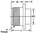
Shell Size Use AIT or Amphenol A Thread Class 2A M +.010 -.000 P Ref. R (TP) +/-.005 S +/- .031 T Dia. +.004 -.002 3102 Ref. L KK Dia. +.010 -.000 X Ref. Y Ref. +/-.045 8S 10-602460-XXX .5000-28 UNEF 0.562 (14.3) 0.110 (2.8) 0.594 (15.1) 0.875 (22.2) 0.120 (3.0) 0.969 (24.6) 0.375 (9.5) 0.595 (15.1) 0.188 (4.8) 10S 10-602461-XXX .6250-24 NEF 0.562 (14.3) 0.110 (2.8) 0.719 (18.3) 1.000 (25.4) 0.120 (3.0) 0.969 (24.6) 0.500 (12.7) 0.595 (15.1) 0.188 (4.8) 10SL 10-602462-XXX .6250-24 NEF 0.562 (14.3) 0.110 (2.8) 0.719 (18.3) 1.000 (25.4) 0.120 (3.0) 0.969 (24.6) 0.625 (15.9) 0.595 (15.1) 0.188 (4.8) 12S 10-602463-XXX .7500-20 UNEF 0.562 (14.3) 0.110 (2.8) 0.812 (20.6) 1.094 (27.8) 0.120 (3.0) 0.969 (24.6) 0.625 (15.9) 0.595 (15.1) 0.188 (4.8) 12 10-602464-XXX .7500-20 UNEF 0.750 (19.1) 0.110 (2.8) 0.812 (20.6) 1.094 (27.8) 0.120 (3.0) 1.344 (34.1) 0.625 (15.9) 0.782 (19.9) 0.188 (4.8) 14S 10-602465-XXX .8750-20 UNEF 0.562 (14.3) 0.110 (2.8) 0.906 (23.0) 1.188 (30.2) 0.120 (3.0) 0.969 (24.6) 0.750 (19.1) 0.595 (15.1) 0.188 (4.8) 14 10-602466-XXX .8750-20 UNEF 0.750 (19.1) 0.110 (2.8) 0.906 (23.0) 1.188 (30.2) 0.120 (3.0) 1.344 (34.1) 0.750 (19.1) 0.782 (19.9) 0.188 (4.8) 16S 10-602467-XXX 1.0000-20 UNEF 0.562 (14.3) 0.110 (2.8) 0.969 (24.6) 1.281 (32.5) 0.120 (3.0) 0.969 (24.6) 0.875 (22.2) 0.595 (15.1) 0.188 (4.8) 16 10-602468-XXX 1.0000-20 UNEF 0.750 (19.1) 0.110 (2.8) 0.969 (24.6) 1.281 (32.5) 0.120 (3.0) 1.344 (34.1) 0.875 (22.2) 0.782 (19.9) 0.188 (4.8) 18 10-602469-XXX 1.1250-18 NEF 0.750 (19.1) 0.141 (3.6) 1.062 (27.0) 1.375 (34.9) 0.120 (3.0) 1.344 (34.1) 1.000 (25.4) 0.782 (19.9) 0.188 (4.8) 20 10-602470-XXX 1.2500-18 NEF 0.750 (19.1) 0.141 (3.6) 1.156 (29.4) 1.500 (38.1) 0.120 (3.0) 1.344 (34.1) 1.125 (28.6) 0.782 (19.9) 0.188 (4.8) 22 10-602471-XXX 1.3750-18 NEF 0.750 (19.1) 0.141 (3.6) 1.250 (31.8) 1.625 (41.3) 0.120 (3.0) 1.344 (34.1) 1.250 (31.8) 0.782 (19.9) 0.188 (4.8) 24 10-602472-XXX 1.5000-18 NEF 0.812 (20.6) 0.141 (3.6) 1.375 (34.9) 1.750 (44.5) 0.147 (3.7) 1.406 (35.7) 1.375 (34.9) 0.782 (19.9) 0.188 (4.8) 28 10-602473-XXX 1.7500-18 NS 0.812 (20.6) 0.141 (3.6) 1.562 (39.7) 2.000 (50.8) 0.147 (3.7) 1.406 (35.7) 1.625 (41.3) 0.782 (19.9) 0.188 (4.8) 32 10-602474-XXX 2.0000-18 NS 0.875 (22.2) 0.156 (4.0) 1.750 (44.5) 2.250 (57.2) 0.173 (4.4) 1.469 (37.3) 1.875 (47.6) 0.782 (19.9) 0.188 (4.8) 36 10-602475-XXX 2.2500-16 UN 0.875 (22.2) 0.156 (4.0) 1.938 (49.2) 2.500 (63.5) 0.173 (4.4) 1.469 (37.3) 2.062 (52.4) 0.782 (19.9) 0.188 (4.8) 40 10-602476-XXX 2.5000-16 UN 0.875 (22.2) 0.156 (4.0) 2.188 (55.6) 2.750 (69.9) 0.173 (4.4) 1.469 (37.3) 2.312 (58.7) 0.782 (19.9) 0.188 (4.8) XXX = Insert layout code. Contact us for correct code. All dimensions in inches (millimeters in parenthesis) PANEL CUTOUTS & THICKNESSAMPHENOL AIT/MS SERIES PANEL CUTOUTS
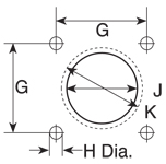
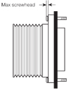
Flange Style 0-2-6B Shell Size G Mounting Hole H Front Mount Diameter J Rear Mount K 8S 0.594 (15.1) 0.134 (3.4) 0.396 (10.1) 0.603 (15.4) 10S 0.717 (18.2) 0.134 (3.4) 0.525 (13.3) 0.728 (18.5) 10SL 0.717 (18.2) 0.134 (3.4) 0.646 (16.4) 0.728 (18.5) 12S/12 0.811 (20.6) 0.134 (3.4) 0.646 (16.4) 0.854 (21.7) 14S/14 0.906 (23.0) 0.134 (3.4) 0.776 (19.7) 0.980 (24.9) 16S/16 0.969 (24.6) 0.134 (3.4) 0.902 (22.9) 1.091 (27.7) 18 1.063 (27.0) 0.134 (3.4) 1.028 (26.1) 1.224 (31.1) 20 1.157 (29.4) 0.134 (3.4) 1.161 (29.5) 1.358 (34.5) 22 1.252 (31.8) 0.134 (3.4) 1.287 (32.7) 1.488 (37.8) 24 1.374 (34.9) 0.154 (3.9) 1.417 (36.0) 1.626 (41.3) 28 1.563 (39.7) 0.154 (3.9) 1.654 (42.0) 1.854 (47.1) 32 1.752 (44.5) 0.177 (4.5) 1.902 (48.3) 2.118 (53.8) 36 1.937 (49.2) 0.177 (4.5) 2.150 (54.6) 2.362 (60.0) 40 2.185 (55.5) 0.177 (4.5) 2.409 (61.2) 2.610 (66.3) ++ 6B panel plug is front mount only. AMPHENOL AIT/MS SERIES PANEL THICKNESS
Shell Size Front Mount Rear Mount 8SL 10S 10SL 12S 12 14S 16S 16 18 20 22 24 28 32 36 40 0.125 (3.18) 0.125 (3.18) 0.125 (3.18) 0.125 (3.18) 0.125 (3.18) 0.187 (4.75) 0.187 (4.75) 0.187 (4.75) 0.187 (4.75) 0.187 (4.75) 0.187 (4.75) 0.187 (4.75) 0.187 (4.75) 0.187 (4.75) 0.250 (6.35) 0.250 (6.35) 0.250 (6.35) All dimensions in inches (millimeters in parentheses) |
|
MS3057-AAMPHENOL AIT/MS SERIES M3057-A CABLE CLAMP
Standard MS3057 cable clamps have dual-clamping action to provide a balanced, positive hold on the wires and greatly reduce moisture transmission. This cable clamp accepts MS3420 bushings. MS3420 bushings can be nested to reduce the inside diameter (ID) to more closely match the diameter of the cable or wire bundle. Standard Clamp Standard Clamp and Telescopic Bushing Shell Size Thread Class 2B Low-Cost Cast Zinc Aluminum w/ Brass Screws Aluminum w/ Stainless Steel Screws Maximum Cable Diameter Low-Cost Zinc With Bushing Bushing Included Bushing ID Inch (MM) 8S/10S 1/2-28 UNEF - MS3057-3A M85049/41-3A 0.250 (6.35) - MS3420-3 0.130 (3.3) 10SL 5/8-24 UNEF **97-3057-1004 MS3057-4A M85049/41-4A 0.312 (7.92) 97-3057-1004-1 MS3420-4 0.220 (5.6) 12/12S 5/8-24 UNEF **97-3057-1004 MS3057-4A M85049/41-4A 0.312 (7.92) 97-3057-1004-1 MS3420-4 0.220 (5.6) 12SL/14S 3/4-20 UNEF **97-3057-1007 MS3057-6A M85049/41-6A 0.438 (11.10) 97-3057-1007-1 MS3420-6 0.312 (7.9) 16/16S 7/8-20 UNEF **97-3057-1008 MS3057-8A M85049/41-8A 0.562 (14.27) 97-3057-1008-1 MS3420-8 0.437 (11.1) 18 1-20 UNEF **97-3057-1010 MS3057-10A M85049/41-10A 0.625 (15.88) 97-3057-1010-1 MS3420-10 0.562 (14.3) 20/22 1 3/16-18 UNEF **97-3057-1012 MS3057-12A M85049/41-12A 0.750 (19.0) 97-3057-1012-1 MS3420-12 0.625 (15.9) 24/28 1 7/16-18 UNEF **97-3057-1016 MS3057-16A M85049/41-16A 0.938 (23.80) 97-3057-1016-1 MS3420-16, -12 0.625 (15.9) 32 1 3/4-18 UNS **97-3057-1020 MS3057-20A M85049/41-20A 1.250 (31.75) 97-3057-1020-1 MS3420-20, -16 0.750 (19.0) 36 2-18 UNS **97-3057-1024 MS3057-24A M85049/41-24A 1.375 (34.92) 97-3057-1024-1 MS3420-24, -20 0.937 (23.8) 40 2 1/4-16 UNS - MS3057-28A M85049/41-28A 1.625 (41.28) - - - Default is CAD OD All dimensions in inches (millimeters in parentheses) MS3057-CAMPHENOL AIT/MS SERIES MS3057-C WATERPROOF CABLE CLAMP
Wire Diameter Inches (MM) Optional Bushings Shell Size Part Number Max. Min. Part Number Max. Wire DIA. (MM) 8S/10S MS3057-3C 0.219 (5.56) 0.095 (2.41) MS3420-3A 0.125 (3.17) 10SL/12/12S MS3057-4C 0.312 (7.93) 0.188 (4.80) MS3420-4A 0.219 (5.56) 12SL/14S MS3057-6C 0.438 (11.12) 0.281 (7.10) MS3420-6A 0.312 (7.93) 16/16S MS3057-8C 0.530 (13.48) 0.312 (7.90) MS3420-8A 0.438 (11.10) 18 MS3057-10C 0.625 (15.87) 0.375 (9.50) MS3420-10A 0.438 (11.10) 20/22 MS3057-12C 0.750 (19.00) 0.500 (12.70) MS3420-12A 0.540 (13.74) 24/28 MS3057-16C 0.940 (23.80) 0.625 (15.90) MS3420-16A 0.750 (19.00) 32 MS3057-20C 1.25 (31.75) 0.921 (23.40) MS3420-20A 0.938 (23.80) 36 MS3057-24C 1.38 (35.00) 1.00 (25.40) MS3420-24A 1.12 (28.50) 40 MS3057-28C 1.62 (41.25) 1.25 (31.80) MS3420-28A 1.125 (31.75) All dimensions in inches (millimeters in parentheses) MS3420AMPHENOL AIT/MS SERIES MS3420 TELESCOPING BUSHINGS
1st Bushing
8S/10S MS3420-3 .130 (3.30) NONE - MS3057-3A 10SL MS3420-4 .220 (5.59) NONE - MS3057-4A 12/12S MS3420-4 .220 (5.59) NONE - MS3057-4A 14S MS3420-6 .312 (7.92) NONE - MS3057-6A 16S MS3420-8 .437 (11.10) NONE - MS3057-8A 16 MS3420-8 .437 (11.10) NONE - MS3057-8A 18 MS3420-10 .562 (14.30) NONE - MS3057-10A 20 MS3420-12 .625 (15.90) NONE - MS3057-12A 22 MS3420-12 .625 (15.90) NONE - MS3057-12A 24 MS3420-16 .750 (19.05) MS3420-12 .625 (15.90) MS3057-16A 28 MS3420-16 .750 (19.05) MS3420-12 .625 (15.90) MS3057-16A 32 MS3420-20 .937 (23.80) MS3420-16 .750 (19.05) MS3057-20A 36 MS3420-24 1.250 (31.75) MS3420-20 .937 (23.80) MS3057-24A 40 MS3420-28 1.375 (34.92) MS3420-24 1.250 (31.75) SE96-28A4 All dimensions in inches (millimeters in parentheses) MS3420-AAMPHENOL AIT/MS SERIES MS3420-A REDUCTION BUSHINGS
For use with MS3057-C cable clamps (style-C) to reduce the wire-sealing diameter. Bushings can be nested, one inside the other, to progressively reduce the inside diameter of the cable clamp. The column labeled “reduction bushings” shows the acceptable nesting options for each clamp. 9767AMPHENOL AIT/MS SERIES 9767 CABLE CLAMPS
Max. Cable Outside Diameter Min. Cable Outside Diameter Shell Size Cable Clamp Inches MM Inches MM Thread Class 10SL/12S/12 9767-12-4 0.219 5.55 0.100 2.54 5/8-24 14S 9767-14-4 0.219 5.55 0.100 2.54 3/4-20 14S 9767-14-6 0.344 8.73 0.176 4.47 3/4-20 16S/16 9767-16-4 0.219 5.55 0.100 2.54 7/8-20 16S/16 9767-16-6 0.344 8.73 0.176 4.47 7/8-20 16S/16 9767-16-8 0.438 11.12 0.177 4.50 7/8-20 18 9767-18-6 0.344 8.73 0.176 4.47 1-20 18 9767-18-8 0.438 11.12 0.177 4.50 1-20 18 9767-18-10 0.563 14.29 0.292 7.42 1-20 20/22 9767-22-8 0.438 11.12 0.177 4.50 1-3/16-18 20/22 9767-22-10 0.563 14.29 0.292 7.42 1-3/16-18 20/22 9767-22-12 0.688 17.46 0.370 9.40 1-3/16-18 24/28 9767-28-10 0.563 14.29 0.292 7.42 1-7/16-18 24/28 9767-28-12 0.688 17.46 0.370 9.40 1-7/16-18 24/28 9767-28-16 0.844 21.43 0.536 13.61 1-7/16-18 32 9767-32-20 1.031 26.19 0.590 14.99 1-3/4-18UNS 36 9767-36-16 0.844 21.43 0.536 13.61 2-18UNS GASKETSAMPHENOL AIT/MS SERIES GASKETS
Synthetic rubber gaskets are used to ensure a moisture-tight seal between a receptacle and the panel. Gaskets are available for front or rear panel mounting of style-0, 2, and 6B connectors. Gasket thickness is approximately .031 inches (1 mm), for nonconductive and low-temperature types. Conductive shielding gaskets contain an imbedded metal screen for EMI/RFI shielding in addition to moisture sealing. Gaskets are available for front or rear panel mounting of connectors. Gasket thickness is .020 inches (.5 mm). Shell Size Non-Conductive Conductive Low-Temperature-67ºF (-55ºC) 8S 10-040450-008 10-040450-08S 10-036675-008 10S/10SL 10-040450-010 10-040450-10S 10-036675-010 12/12S 10-040450-012 10-040450-12S 10-036675-012 14/14S 10-040450-014 10-040450-14S 10-036675-014 16S 10-040450-016 10-040450-16S 10-036675-016 16 10-040450-016 10-040450-16S 10-036675-016 18 10-040450-018 10-040450-18S 10-036675-018 20 10-040450-020 10-040450-20S 10-036675-020 22 10-040450-022 10-040450-22S 10-036675-022 24 10-040450-024 10-040450-24S 10-036675-024 28 10-040450-028 10-040450-28S 10-036675-028 32 10-040450-032 10-040450-32S 10-036675-032 36 10-040450-036 10-040450-36S 10-036675-036 40 10-040450-040 10-040450-40S 10-036675-040 METAL DUST CAPSAMPHENOL AIT/MS SERIES METAL DUST CAPS WITH SASH CHAIN & DUMMY RECEPTACLES
Metal dust caps are used to protect the contacts when the connectors are left unmated. Dust caps come with metal chain lanyards. Dummy receptacles are for front or rear panel mounting. The center of the dummy receptacle is closed. Dummy receptacles mount on the same centers and have the same outside dimensions as MS3102 receptacles. A version with a clearance hole through the middle of the connector is also available. Call for ordering information. Dust Caps Dust Caps Dummy
8S MS25042-8* MS25043-8* MS3105-8S 10S/10SL MS25042-10* MS25043-10* MS3105-10S 12/12S/12SL MS25042-12* MS25043-12* MS3105-12S 14S MS25042-14* MS25043-14* MS3105-14S 16S MS25042-16* MS25043-16* MS3105-16S 16 MS25042-16* MS25043-16* MS3105-16 18 MS25042-18* MS25043-18* MS3105-18 20 MS25042-20* MS25043-20* MS3105-20 22 MS25042-22* MS25043-22* MS3105-22 24 MS25042-24* MS25043-24* MS3105-24 28 MS25042-28* MS25043-28* MS3105-28 32 MS25042-32* MS25043-32* MS3105-32 36 MS25042-36* MS25043-36* MS3105-36 40 MS25042-40* MS25043-40* MS3105-40 *Contact us for all other platings *D = Olive drab chrome over cadmium DA = Anodized |
|
SOLDER CONTACTSAMPHENOL AIT/MS SERIES SOLDER CONTACTS
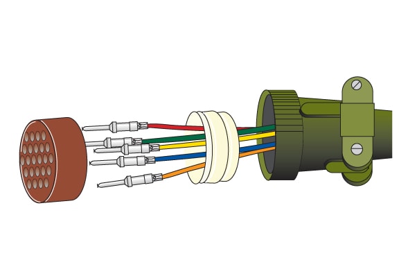
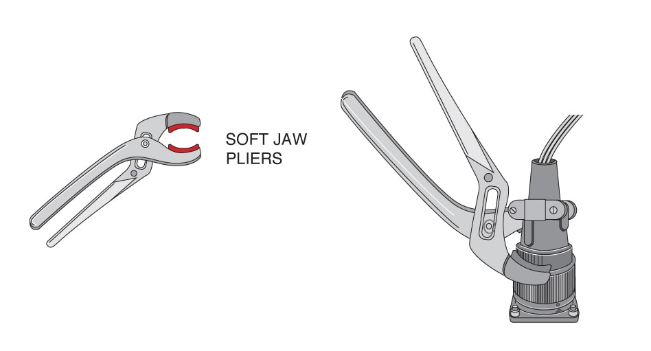
STEP 1: Slide the rear accessories over the wire bundle in the proper sequence for re-assembly: cable clamp and/or endbell first, then ferrule and (if used) coupling nut. STEP 2: Insert individual wires through the proper holes in the grommet. Use isopropyl alcohol as a lubricant. STEP 3: Solder wires to appropriate contacts on the rear of the connector. Information on standard soldering practices is available upon request. Please contact us. STEP 4: Fixture the connector for reassembly using endbell assembly tools. STEP 5: Slide the grommet down the wires (lubricating the grommet with isopropyl alcohol will help). STEP 6: Fill all unused grommet cavities with a wire hole filler to maintain the sealing integrity of the connector. STEP 7: Slide coupling nut, ferrule, and endbell accessories over rear of the connector and tighten. Click here for tooling. CRIMP TOOL OPERATIONAMPHENOL AIT/MS SERIES CRIMP TOOL OPERATION
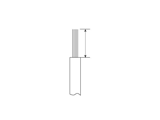
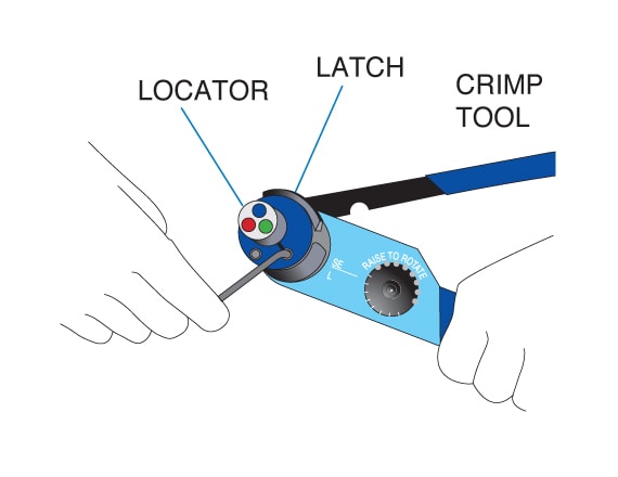
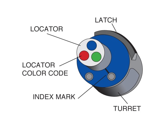
STEP 1: Strip the wires to the appropriate length. See strip lengths on the Contact Selection Guide. STEP 2: Open the crimp tool by squeezing the handles. Push the latch on the turret to release the locator. Attach the turret to the crimp tool using the two captive hex bolts in the turret.
NOTE: Hand-crimp tools can be used with size 16S, 16 & 12 contacts. Size 8, 4 and 0 contacts require the use of air-powered crimp tools. Contact us for assistance in the use of these tools. STEP 3: Select the proper locator position for your contact by rotating the locator until the proper color is aligned with the index mark. Push locator back down until it snaps into position. Contact Size Pin Locator Color Socket Locator Color 16S Blue Blue 16 Green Red 12 Red Red
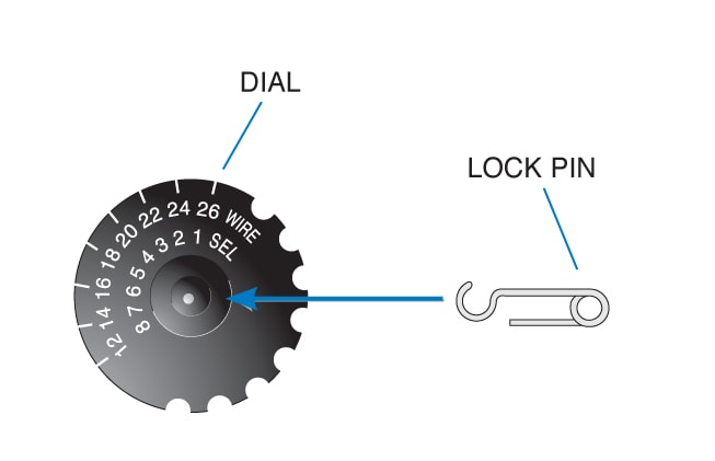
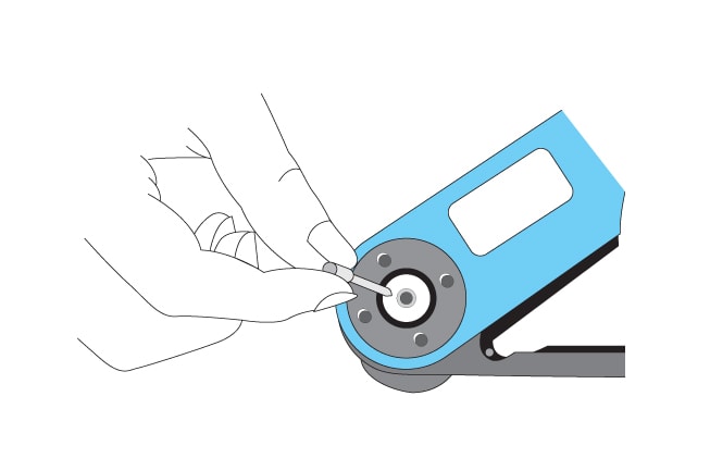
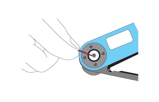
STEP 4: Adjust dial for proper wire gauge. To change the dial setting, remove the lock pin and lift center of dial. Turn to the desired wire gauge. Replace lock pin on dial. STEP 5: Cycle the tool before inserting the contact to be sure the tool is in the open position. Drop the contact, mating end first, into the crimp cavity of the tool. Squeeze the tool handle just enough to grip the contact without actually crimping it. STEP 6: Insert the stripped wire into the contact with a slight twisting motion. Be sure all wire strands are inside the contact. Squeeze the handle to cycle the tool. The handle will not release until the contact is completely crimped.
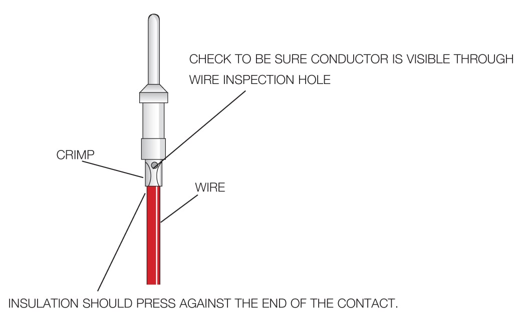
Crimp Tensile Strength Initial minimum pullout force in lbs. (before conditioning) Size Wire Guage (AWG) Lb. 16 20 18 16 20 40 50 12 14 12 70 110 8 8 185 4 4 450 0 0 800 STEP 7: Remove the crimped contact. Pull on the wire slightly to be sure it is properly crimped. Be sure the contact is not bent or damaged in any way. Visually inspect the crimp. MICRO-SECTIONS: Enlargement of micro-section permits a final inspection of crimp quality. This test is recommended whenever new tools or new types of wire or contacts are used. CONTACT INSERTIONAMPHENOL AIT/MS SERIES CONTACT INSERTION
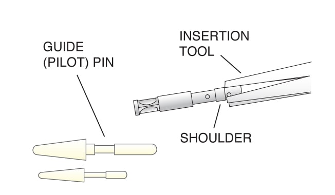
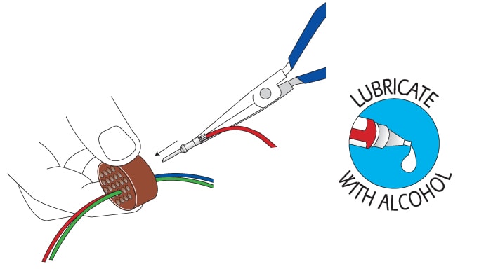
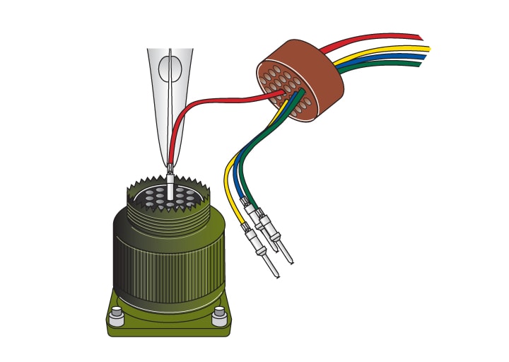
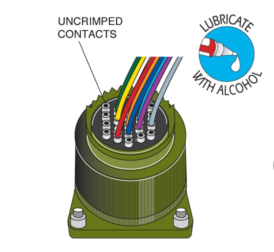
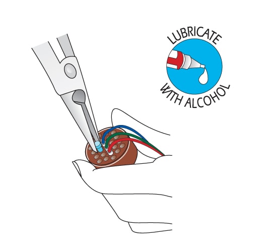
STEP 1: Slide the rear accessories over the wire bundle in the proper sequence for re-assembly: cable clamp and/or endbell first, then ferrule, and coupling nut. STEP 2: Use the proper insertion tool from the Contact Selection Chart. Place the contact in the tool. The tool should push against the shoulder of the contact. Contact sizes 16S, 16, and 12 use a pliers-style tool. Contact sizes 8, 4 and 0 use a tool with a C-shaped shaft. STEP 3: Lubricate the grommet with isopropyl alcohol (do not use any other type of lubricant). Insert the contact through the appropriate cavity in the grommet. Sizes 16S, 16 and 12 socket contacts must be installed using guide (pilot) pins. See the Contact Selection Chart for Insertion Guide (Pilot) Pin part numbers.
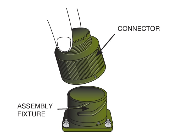
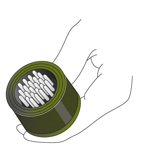
STEP 4: Place the connector into an assembly fixture. Fixtures are available for production use; contact us using the information below. If you are not using a fixture, be sure to allow clearance on the mating face of the connector for the guide pins to come through the connector during insertion. STEP 5: Lubricate the contact cavities of the connector insulator with isopropyl alcohol (do not use any other type of lubricant). STEP 6: Using guide pins where necessary, push straight down with a firm, even pressure until the contact snaps into position in the proper cavity. Start at the center of the pattern and work toward the outer edges.
STEP 7: Fill any unused cavities with contacts. STEP 8: Check the mating face of the connector to ensure that all of the same size contacts are on the same plane (fully inserted). If not, the contact is not fully inserted. Remove the contact using the proper extraction tool and procedure, and reinsert. Do not attempt to reinsert the insertion tool to correct the problem. STEP 9: wire hole filler must be inserted into the grommet behind the unused contacts to maintain the sealing integrity of the connector. See the Contact Selection Chart for wire hole fillers. STEP 10: Place the connector back in the fixture for re-assembly. Slide the connector accessories back down the cable over the rear of the connector and tighten. Use the appropriate endbell tools. CONTACT EXTRACTIONAMPHENOL AIT/MS SERIES CONTACT EXTRACTION
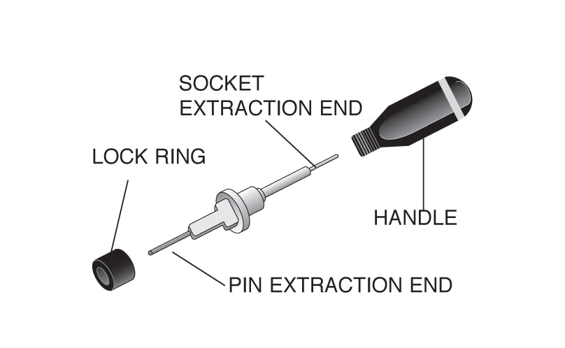
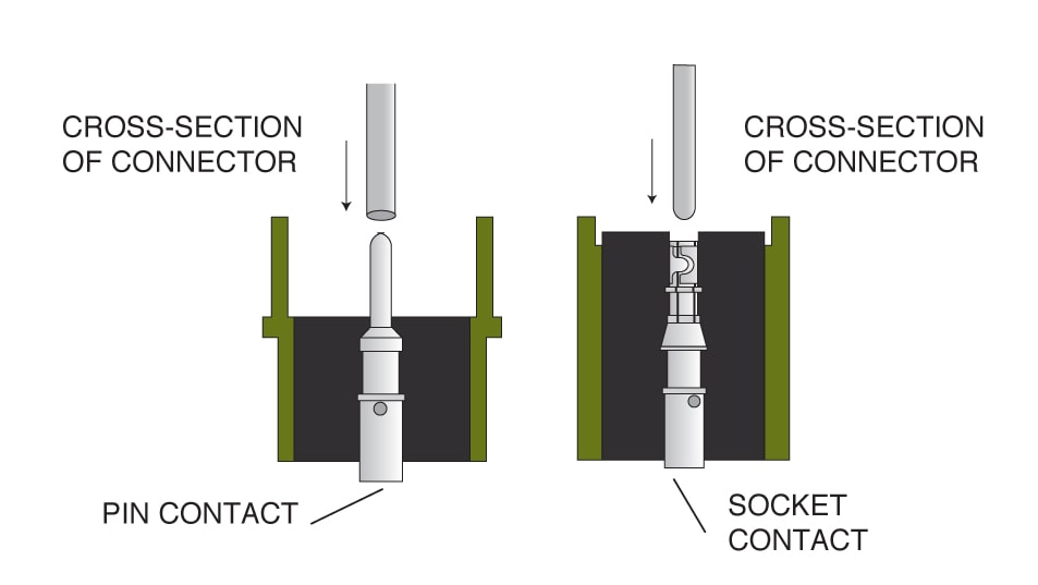
STEP 1: Remove the endbell accessories and slide them back over the wires. Use the appropriate endbell tools. STEP 2: Use the proper extraction tool from the Contact Selection Chart. The extraction tool can be used for both pin and socket contacts by removing the shaft from the handle and reversing it for pin or socket extraction.
STEP 3: On the mating face of the connector, insert the tool over the pin contact or into the socket contact until the tool touches bottom. Apply a slow, continuous pressure to push the contact out through the rear of the connector. When the shoulder of the tool "thunks" against the insulator, the contact is extracted. STEP 4: Carefully remove the extraction tool from the connector to avoid damage to the insulator. |
Philadelphia
19116
Click here for the contact information of the branch nearest you.


